








Choosing a laser rangefinder module interface is an architecture decision, not a connector preference. UART, TTL-level serial, RS422, and CAN can all carry measurement information, but they behave differently when cable length, noise exposure, topology, host software, serviceability, and timing requirements change.
Lumexis develops rangefinder modules for OEM systems. This comparison helps engineering teams frame the interface question early enough to avoid redesigning the harness or controller later.
Laser rangefinder module interface: start with the system
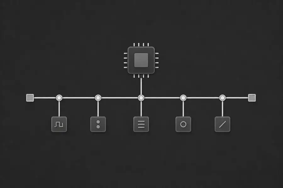
Before choosing an interface, answer four questions: How far is the module from the host? Is the connection point-to-point or shared among multiple devices? What electrical environment will the cable cross? And who owns error recovery in the finished system?
Those answers narrow the field quickly. A compact module beside a controller board may need only a simple local serial connection. A remote sensing head may benefit from differential signaling. A device that belongs on a shared equipment network may require a bus-oriented architecture.
UART and TTL-level serial: direct and local
UART is asynchronous serial communication; TTL-level serial usually describes the electrical logic levels used around that UART connection. The pairing is common in compact, local integrations because it uses few signals and is easy for a microcontroller to process.
The tradeoff is that it depends heavily on the installed electrical environment. Confirm voltage compatibility, common reference, cable route, and startup behavior. Do not use the phrase “TTL” as a substitute for a complete interface definition; it does not state the protocol, connector, or permitted voltage range.
RS422: point-to-point over a more demanding cable path
RS422 uses differential pairs for a point-to-point connection. It can be an appropriate option where the rangefinder module and host controller are separated by a longer route or more electrically active installation. Correct pair routing, termination, grounding, and connector design remain essential.
Read our dedicated guide to RS422 laser rangefinder modules when evaluating a remote sensing head. The guide focuses on the harness and validation details that determine whether an interface performs consistently after installation.
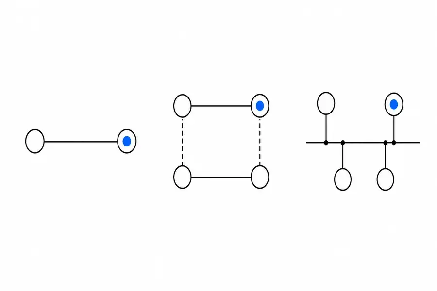
CAN: networked equipment architecture
CAN is a networked communication approach with its own physical-layer topology and higher-level message design considerations. It is attractive when multiple devices share a system bus and the host wants structured status, diagnostics, and measurement messages within a network architecture.
CAN is not simply a longer UART cable. The bus topology, end termination, node identifiers, update behavior, error handling, and network load must be engineered together. If a project does not need a shared network, its added integration work may not create value.
A practical comparison table
| Interface | Best-fit architecture | Main engineering focus |
|---|---|---|
| UART / TTL serial | Nearby point-to-point controller | Logic compatibility, framing, reference path |
| RS422 | Remote point-to-point controller | Differential cable design, termination, installed validation |
| CAN | Shared equipment network | Bus topology, message design, network diagnostics |
The table is a selection aid, not a substitute for module-specific documentation. Availability and implementation details depend on the exact module configuration.
Make the decision testable
Write an interface acceptance plan before the hardware freeze. It should cover power-up, normal measurement traffic, invalid frames, cable disconnect and reconnection, host reset, and the final installed cable route. Use the final enclosure and power system—not only a bench adapter.
The laser rangefinder module UART integration guide is a useful companion for cross-functional reviews. For optical fundamentals, see how a laser rangefinder works.
Keep the protocol contract separate from the wire choice
An electrical interface and a message protocol are related but not interchangeable. A connector drawing should state pin roles and electrical limits, while a protocol record should state frame boundaries, message ownership, fault behavior, and recovery rules. Keeping these documents separate prevents a wiring change from becoming an undocumented firmware change.
Lumexis can align module selection with the intended electrical and software architecture, then support a clear validation path from prototype through production. Contact our team to discuss your integration requirements.
Technical reading: CAN in Automation’s high-speed transmission overview explains differential bus topology and end termination for CAN physical layers.
FAQ
Which interface is best for a short internal connection?
UART or TTL-level serial is often the simplest choice for a nearby point-to-point controller, provided the electrical levels and grounding arrangement are compatible. Confirm the exact module documentation before assigning pins or firmware settings.
When does RS422 become more appropriate?
RS422 is worth evaluating when a point-to-point link must cross a longer or more electrically complex cable route. The benefit depends on correct differential-pair routing, termination, and validation in the final installation.
Is CAN always more reliable than serial?
No. CAN addresses a different system architecture. It can be effective for shared networks, but it requires a correctly designed bus and message model. A simple local point-to-point connection may be better served by a simpler interface.
Can we select the interface after the mechanical design is complete?
It is possible, but expensive. Cable paths, connector access, grounding, enclosure partitions, and service procedures influence interface behavior. Decide early and validate with production-representative hardware.