
Two 1.5 µm source options for selected LiDAR and sensing architectures.
1535 nm & 1550 nm OEM source platform
LiDAR Pulsed Fiber Lasers
Lumexis develops compact nanosecond pulsed fiber lasers for LiDAR, remote sensing, mapping, industrial inspection and scientific instruments. The existing product range includes compact 1535 nm and 1550 nm sources, high-peak-power fiber lasers and an eight-channel LiDAR light source. Published specifications span peak power from 1.16 kW to up to 15 kW, 1–3000 kHz repetition, 1–60 ns pulse width and FC/APC, FC/UPC or multimode-fiber optical output.
Peak power, average power, repetition rate and pulse width are configuration-dependent. Confirm the selected model’s datasheet before freezing the optical, electrical or thermal design.
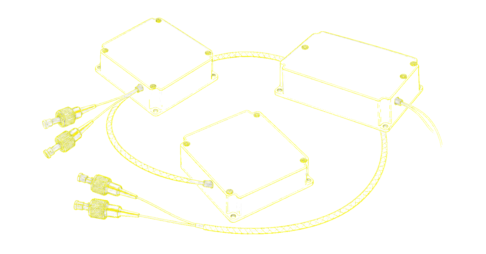
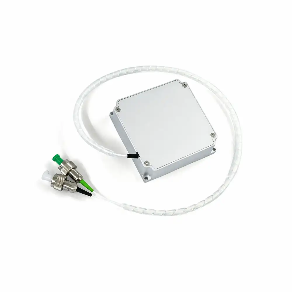 1535 nm / 1.2 kW
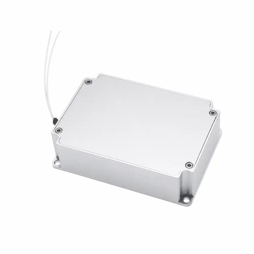 1550 nm / 1.6 kW
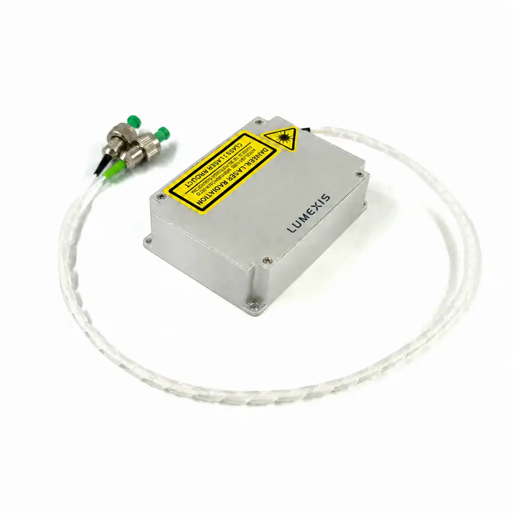 1550 nm / 3 kW
Published peak-power classes from compact to high-power source architectures.
Model and configuration dependent nanosecond pulse settings.
Published repetition range across the existing product archive.
Connector option is model dependent; verify with the selected specification.
Published range for the series; confirm the actual host thermal boundary.
Complete product range
Choose the source around pulse conditions and the finished LiDAR architecture.
Peak power alone does not define system performance. Compare wavelength, pulse width, repetition rate, average-power budget, connector type and the mechanical/thermal interfaces before design release.
1535-LXMC1.2KW
1535nm 1.2kW Pulsed Fiber Laser
100 / 500 / 2000 kHz; 2.5 / 3 / 3.5 ns; 1.2 W average; FC/APC + FC/UPC.
1550-LXMC1.6KW
1550nm 1.6kW Pulsed Fiber Laser
100 / 500 / 2000 kHz; 2.5 / 3 / 3.5 ns; 2.1 W average; FC/APC.
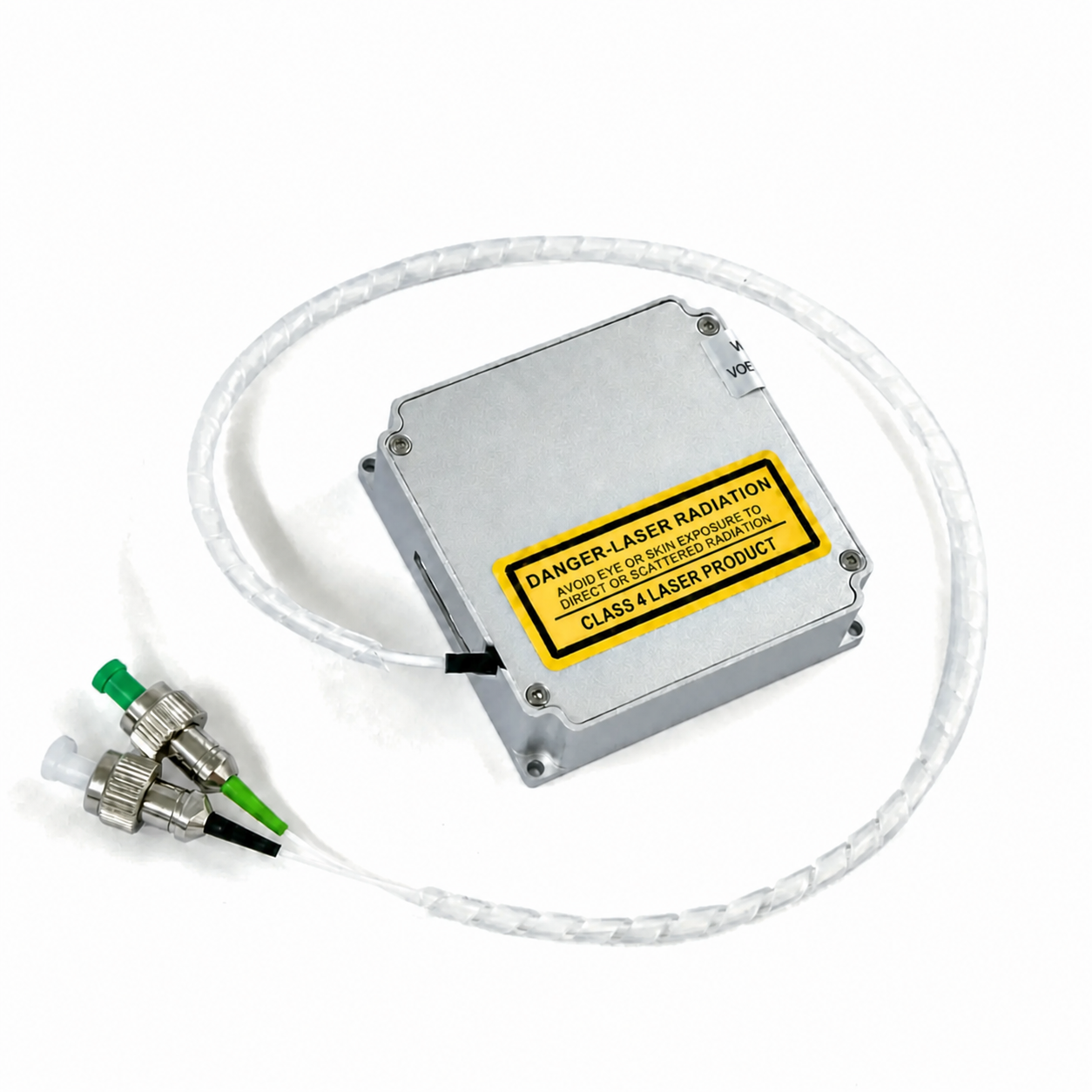
1535 NM PULSED
1535nm Pulsed Fiber Laser
3 ns typical; 100–2000 kHz adjustable; 0.7–1.1 W average; FC/APC + FC/UPC.
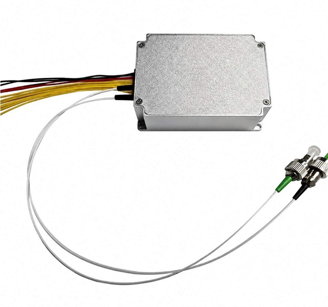
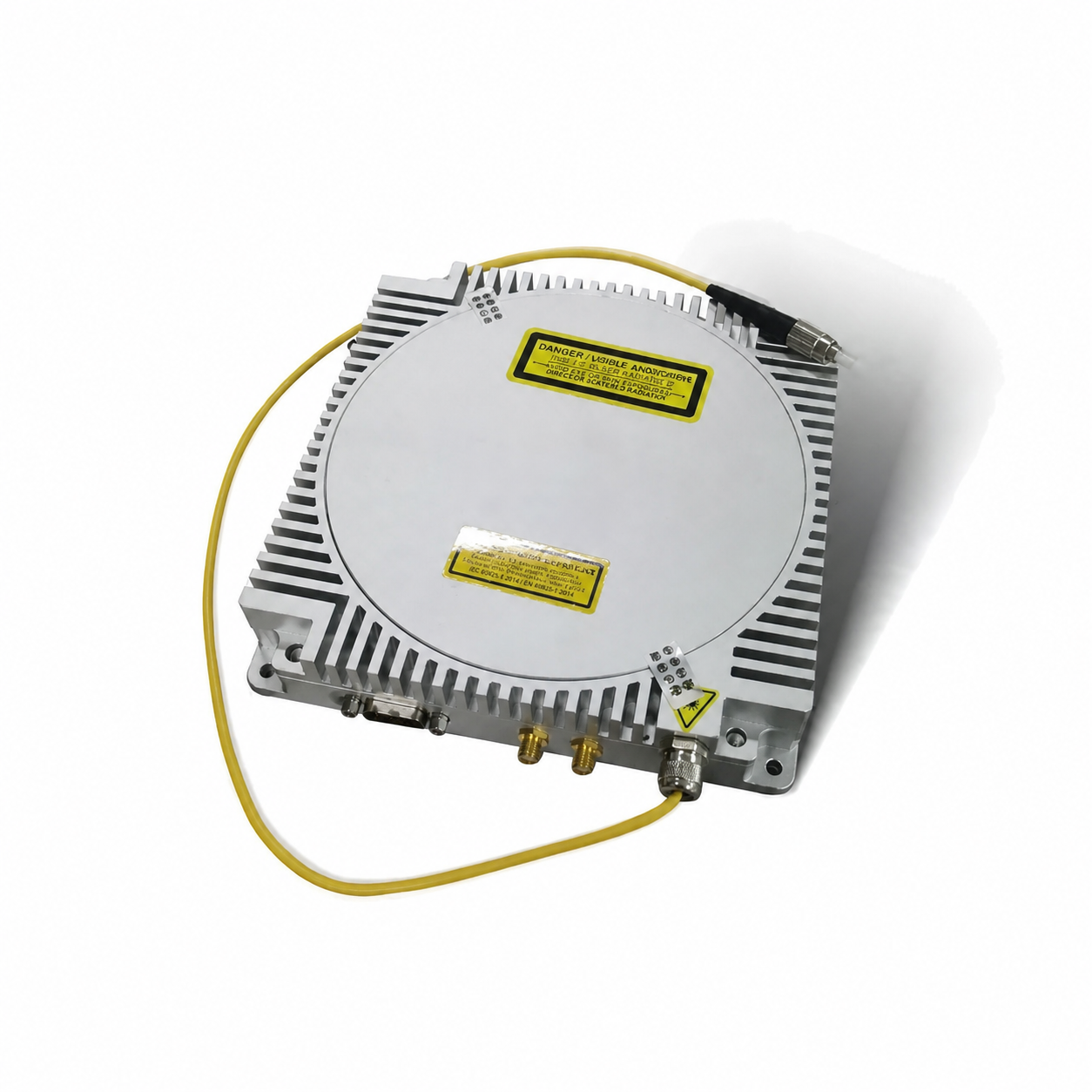
1550 HIGH PEAK
1550nm High Peak Power Fiber Laser
4 ns; 30–100 kHz; 3–6 W average; multimode fiber output.
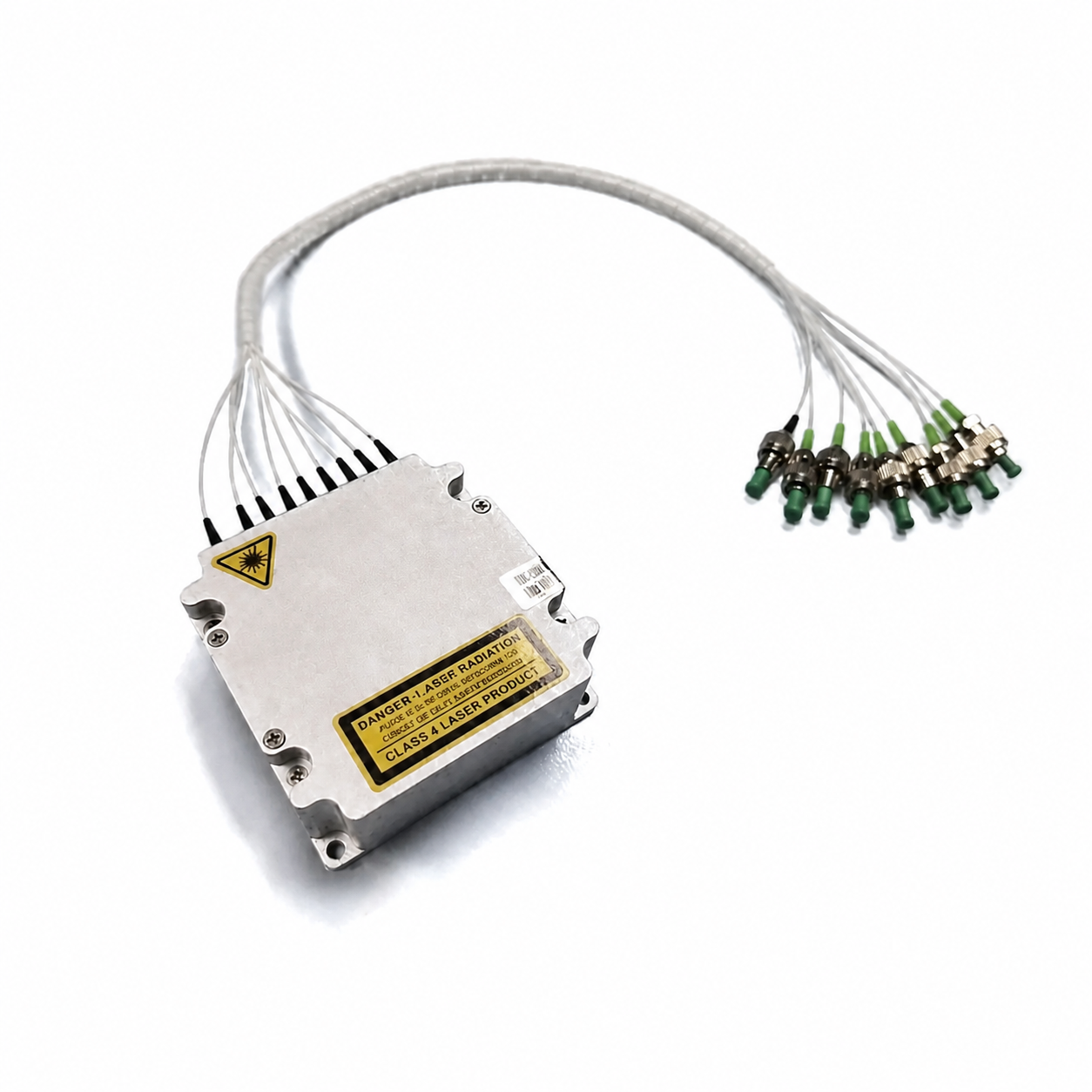
1550 8-IN-1
1550nm LiDAR Light Source 8-in-1
Integrated multi-channel source architecture; repetition rate and interface reviewed per application.
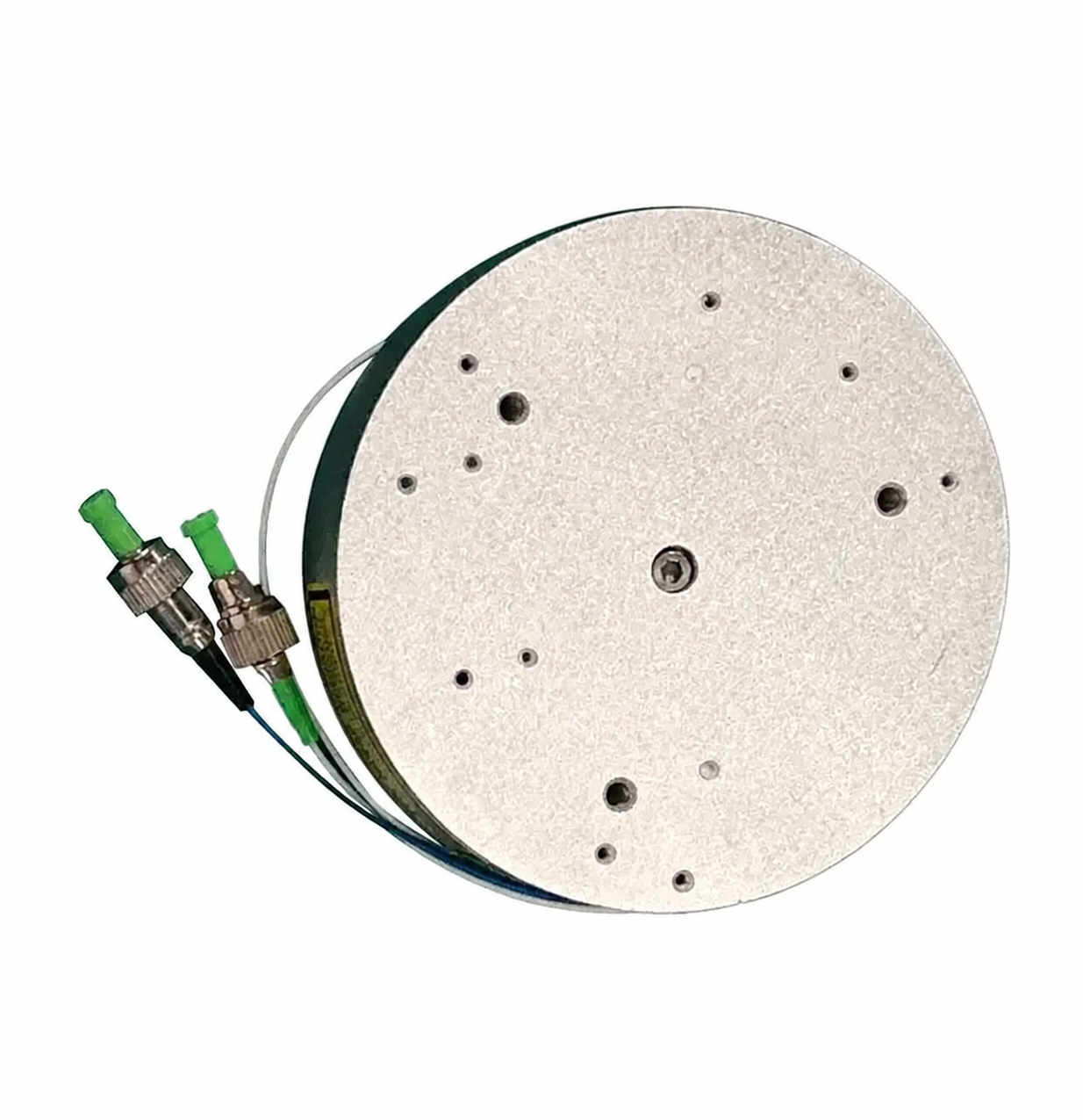
Model comparison
Compare the published technical parameters in one table.
Numbers below are the local published selection values. The order-specific technical specification defines the final operating point, interface and acceptance conditions.
| Model | Wavelength | Peak power | Repetition settings | Pulse width settings | Average power | Optical output | Dimensions | Operating temp. |
|---|---|---|---|---|---|---|---|---|
| 1535-LXMC1.2KW | 1535 nm | 1.2 kW | 100 / 500 / 2000 kHz | 2.5 / 3 / 3.5 ns | 1.2 W | FC/APC + FC/UPC | 55 × 55 × 16 mm | −40 to +75°C |
| 1550-LXMC1.6KW | 1550 nm | 1.6 kW | 100 / 500 / 2000 kHz | 2.5 / 3 / 3.5 ns | 2.1 W | FC/APC | 50 × 70 × 19 mm | −40 to +75°C |
| 1550-LXMC3KW | 1550 nm | 3 kW | 50 / 500 / 2000 kHz | 3 / 3 / 5 ns | 2.0 W | FC/APC | 50 × 70 × 19 mm | −40 to +75°C |
| 1535 nm Pulsed | 1532–1537 nm | 1160 W | 100–2000 kHz | 3 ns typical | 0.7–1.1 W | FC/APC + FC/UPC | 55 × 55 × 16 mm | −40 to +85°C |
| 1550 nm Compact | 1547–1553 nm | 1–2 kW | 0.1–2 MHz | 1–10 ns | 0.95–1.05 W | FC/APC | 50 × 70 × 19 mm | −40 to +70°C |
| 1550 nm High Peak | 1545–1555 nm | 12 kW typ.; up to 15 kW | 30–100 kHz | 4 ns | 3–6 W | Multimode fiber | 160 × 160 × 30 mm | −40 to +60°C |
| 1550 nm Erbium | 1545–1555 nm | 2 kW | 1–3000 kHz | 1–60 ns | 0.8 W | FC/APC | Ø90 × 24.5 mm | −40 to +70°C |
Specification note: supply is 9 / 12 / 13 V for all three listed models. Pulse and repetition values represent listed configuration settings, not a guarantee that every combination is available. Confirm selection with Lumexis engineering.
Nanosecond optical pulse
Seed pulseFiber amplifierPulse shapingFiber output
Pulsed-fiber-laser fundamentals
From seed pulse to fiber-delivered LiDAR output.
A pulsed fiber laser creates a controlled seed waveform and amplifies it through a fiber-based gain path. The output pulse width, peak power, repetition rate and average power must be selected together because they determine optical energy delivery, thermal loading and the timing margin of the finished sensing system.
Pulse timing
The seed defines the timing reference and starting pulse shape for the system.
Fiber gain path
Amplification raises the optical pulse to the required peak-power class.
Connector interface
Fiber connector selection must match host optics, contamination control and service needs.
External trigger
Host timing, electrical grounding and trigger behavior should be validated together.
Selection knowledge
Four linked parameters define the usable pulse envelope.
These sources are selected as part of an optical system. Use the actual receiver, scanning architecture, optical loss, thermal path and data-acquisition timing when choosing a model and its operating point.
Signal margin
Peak power affects the available optical intensity during the pulse. Evaluate it together with receiver sensitivity, optical losses and the host safety assessment.
Timing resolution
Pulse width contributes to time-of-flight resolution, while the practical system result also depends on detector, electronics and signal processing.
Point density
Repetition rate influences measurement cadence, sample density, data throughput and total thermal load in the final instrument.
Thermal budget
Average optical power and electrical input define cooling and power-supply requirements. Do not size the thermal path around peak power alone.
Pulse energy ≈ peak power × pulse width
Use consistent units: 1 kW × 1 ns ≈ 1 µJ. This is a first-order selection relationship; actual delivered pulse energy and available operating combinations must be taken from the chosen model’s technical specification.
Application solutions
Designed for civil, industrial and scientific LiDAR architectures.
Application performance comes from the entire instrument: source, transmit optics, scanner, receiver, timing electronics, calibration and operating environment. We support model selection around that complete chain.

01 / TERRAIN MAPPING
Terrain mapping
Airborne LiDAR source integration for topographic surveying and terrain-model generation.

02 / INFRASTRUCTURE
Railway & infrastructure corridors
Pulsed-source architectures for rail, road and linear-infrastructure measurement.

03 / INDUSTRIAL
Industrial mobile mapping
Compact optical sources for mobile scanning and industrial spatial measurement.

04 / FORESTRY & AGRICULTURE
Forestry & agriculture
Airborne LiDAR workflows for canopy structure, landform and agricultural mapping.
Mechanical & electrical integration
Resolve the fiber, trigger, power and thermal interfaces before freezing the host enclosure.
Use the model-specific drawing, connector definition and operating limits as the design baseline. Validate the assembled host system—including fiber routing, bend management, electrical noise, thermal transfer and service access—rather than the bare laser in isolation.
Clean, protect, align
Match the FC/APC or FC/UPC interface to host optics and protect end faces from contamination.
Time the system
Confirm trigger polarity, delay, jitter and grounding with the selected model documentation.
9–13 V supply
Verify startup, current capacity, ripple and cable drop—not voltage alone.
Build the heat path
Provide controlled chassis contact and test temperature at the actual installed operating point.
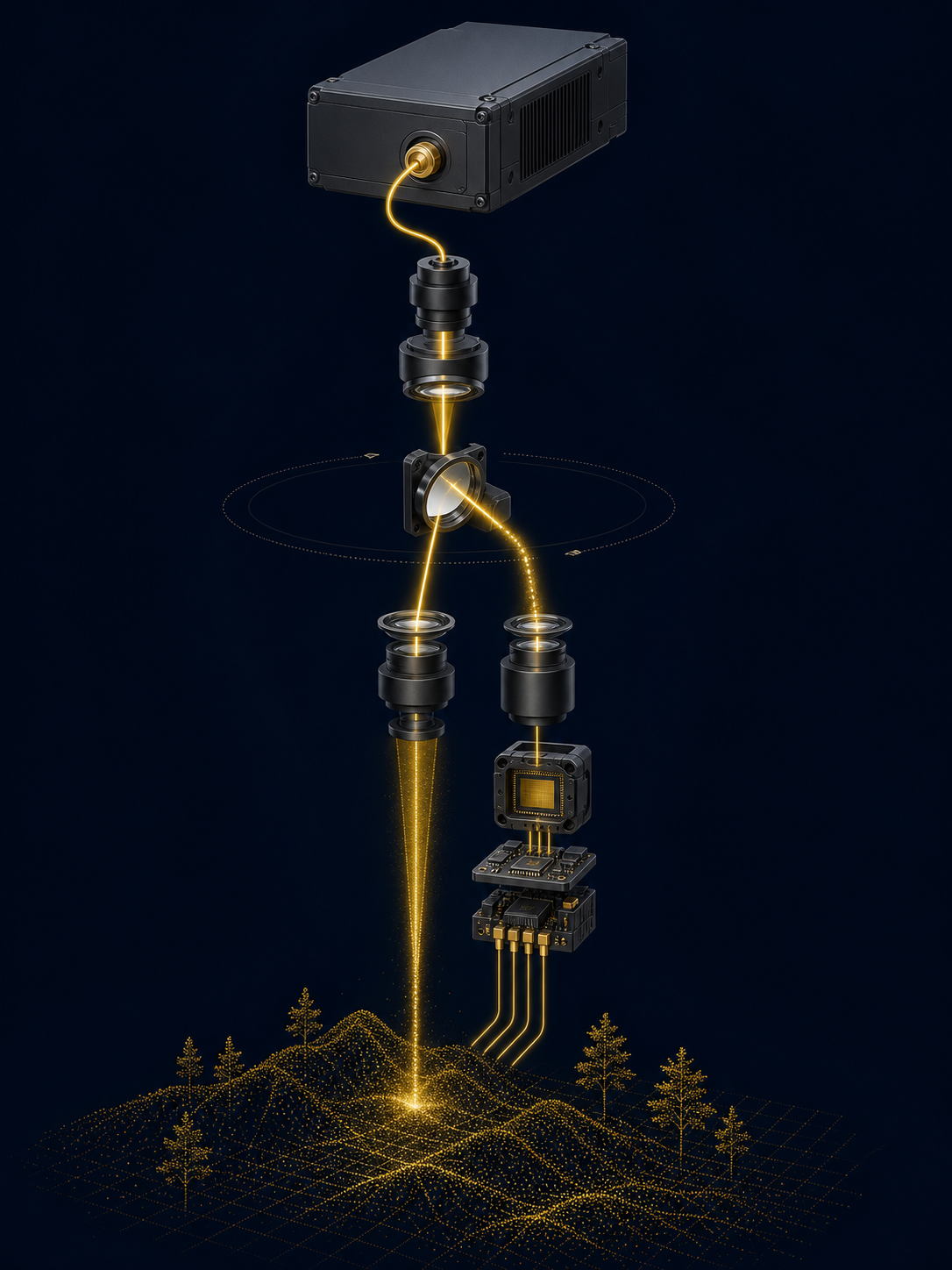
Testing & quality control
Source-level checks focus on pulse, optical delivery and integration-relevant reliability.
The detailed acceptance plan and environmental qualification are defined for the quoted configuration. Request the applicable record and test scope when planning samples or volume delivery.
Wavelength
Verify the source output against the selected 1535 nm or 1550 nm model specification.
Pulse output
Check pulse power and average output at the defined operating point.
Timing behavior
Verify pulse width, trigger relationship and repetition behavior as applicable.
Fiber delivery
Inspect optical connector condition and output stability at the fiber interface.
Environmental screen
Temperature, vibration and aging scope are defined by the project qualification plan.
Traceable delivery
Model identification, serial traceability and outgoing-inspection information can accompany shipment.
Safety and compliance: the pulsed fiber laser is an OEM source. The completed instrument is responsible for final laser-safety classification and any applicable approvals in its final optical and operating configuration.
Pre-sales FAQ
Clarify the system inputs before requesting samples.
These questions make the technical discussion more productive and allow us to recommend the right source configuration, integration documents and validation path.
How do I choose between 1535 nm and 1550 nm?
Start with the receiver sensitivity, transmit optics, detector choice, atmospheric path, final safety assessment and existing system architecture. The wavelength should be selected for the complete system rather than from a peak-power number alone.
What does peak power tell me?
It indicates the instantaneous optical power during the pulse. It must be read together with pulse width, repetition rate, average power, fiber delivery and the receiver’s signal margin. It is not a stand-alone measure of final system range or point-cloud quality.
Can I select any pulse-width and repetition-rate combination?
No. The values on this page identify published configuration settings. Available combinations, triggering behavior and performance limits are confirmed in the selected model’s technical specification.
Which fiber output should I use?
The 1535 nm 1.2 kW model lists FC/APC + FC/UPC; the two 1550 nm models list FC/APC. Connector, fiber routing, bend radius, cleanliness and downstream optical compatibility should all be verified during design-in.
What host information is needed for a sample recommendation?
Provide target application, wavelength preference, desired pulse and repetition regime, host optical layout, receiver type, supply rail, available thermal path, enclosure volume, operating temperature and planned evaluation date.
Can Lumexis support customised integration?
We can evaluate OEM requests around optical output, mechanical interface, electrical connection, trigger configuration and programme documentation. Feasibility depends on the requested performance, validation scope and production requirement.
Start an OEM source review
Select the pulsed source with the complete LiDAR system in view.
Send your required wavelength, pulse regime, receiver and optical layout, mechanical envelope, electrical supply and thermal conditions. We will identify the relevant models and engineering documents for evaluation.