
Civil airborne ranging
UAV Laser Ranging: Start With the Measurement Job
Lumexis develops compact 1535 nm laser rangefinder modules for civil airborne remote sensing, terrain-height measurement, infrastructure standoff measurement, camera-assisted point ranging, and scientific surface profiling.
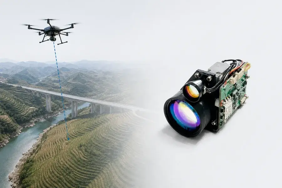
Lumexis develops and manufactures compact 1535 nm laser rangefinder modules for civil airborne measurement systems. Our modules give payload engineers a direct Time-of-Flight distance channel that can support terrain-height measurement, infrastructure standoff measurement, camera-assisted point ranging, and scientific surface profiling.
Start with the measurement job, not the largest range number.
For a fast module match, define:
- whether the required output is slant range, vertical height, or a georeferenced surface point;
- the normal and maximum sensor-to-surface distance;
- the surface material, slope, vegetation, moisture, and expected incidence angle;
- the available mass, envelope, average power, and peak-power budget;
- the required measurement rate, timestamp accuracy, and invalid-reading behavior;
- the host sensors available for position, attitude, pointing angle, and camera alignment.
Quick route: Send Lumexis your height envelope, surface type, payload budget, and host interface.
Start with the airborne measurement task
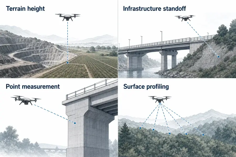
Application fit
Match the optical source to the real measurement task
Four civil airborne laser ranging applications: terrain height, infrastructure standoff, point measurement, and surface profiling.
| Application | Output the range channel can support | What the host must add | Start the RFQ with |
|---|---|---|---|
| Terrain-height measurement | Distance to the illuminated terrain or structure | Attitude compensation for vertical height; terrain logic if measuring above the surface directly below the platform | height envelope, surface type, platform tilt, rate, mass |
| Civil infrastructure inspection | Standoff to a bridge element, slope, tower, rail-side structure, or large asset | Camera or pointing-angle alignment; target selection; platform position when coordinates are required | target size, material, angle, maximum standoff, vibration |
| Camera-assisted point measurement | Range along the camera or gimbal line of sight | Camera intrinsics, camera-to-rangefinder boresight, platform position and attitude | field of view, alignment tolerance, timestamp, interface |
| Scientific remote sensing | Repeated range samples along a known trajectory | GNSS/IMU, time synchronization, calibrated mounting geometry, data logging | trajectory, sample spacing, surface response, coordinate frame |
| Surface profiling | A series of range returns along commanded look directions | A scanning or pointing mechanism and processing that assigns an angle and pose to each sample | scan geometry, angular encoder, rate, overlap, calibration |
A single-point rangefinder is a strong fit when
- the system needs one absolute distance along a known look direction;
- the payload already contains a camera, gimbal, GNSS receiver, IMU, or angular encoder;
- low mass and low average power matter more than dense point-cloud output;
- measurement rates of 1–10 Hz suit the required update and logging workflow;
- the target is a terrain patch or civil structure large enough to intercept the useful beam footprint.
Choose a scanning LiDAR instead when
- the primary deliverable is a dense 2D or 3D point cloud from every pass;
- high pulse density and wide angular coverage are fundamental requirements;
- canopy structure or multiple vertical layers must be resolved systematically;
- centimetre-class mapping accuracy is required from a fully integrated survey payload.
A laser rangefinder module, laser altimeter, and scanning LiDAR all measure optical Time of Flight, but they are not interchangeable products. The correct choice depends on the output data, sampling geometry, and calibration chain—not the wavelength alone.
Match the Lumexis module to range and payload limits
For civil UAV payloads, mass, envelope, receive aperture, power, minimum range, and communication interface often eliminate unsuitable options before maximum range does.
The range values below are reference-target values, not guaranteed flight heights. They are tied to a 2.3 × 2.3 m target with reflectivity of at least 0.3 under the visibility condition stated in the source specification. A broad terrain footprint, dark roof, wet surface, canopy, oblique slope, contaminated window, or unstable line of sight can produce a different usable range.
| Lumexis model | Reference-target range | Receive aperture | Beam divergence | Minimum range | Accuracy | Rate | Maximum dimensions | Mass | Typical average power at 1 Hz |
|---|---|---|---|---|---|---|---|---|---|
| 1535-LXCJ0300 | ≥3.2 km* | Φ16 mm | ≤0.6 mrad | ≤15 m | ≤±1 m | 1–10 Hz | 48 × 21 × 31 mm | 33 ± 1 g | ≤0.8 W |
| 1535-LXCJ0500 | ≥5 km** | Φ16 mm | Confirm by configuration | ≤15 m | ≤±1 m | 1–10 Hz | 50 × 23 × 33.5 mm | ≤40 g | ≤1 W |
| 1535-LXCJ0600 | ≥6 km** | Φ21 mm | ≤0.3 mrad | ≤20 m | ≤±1 m | 1–10 Hz | 65 × 40 × 28 mm | ≤55 g | ≤1 W |
| 1535-LXCJ0700 | ≥7 km** | Φ25 mm | ≤0.3 mrad | ≤30 m | ≤±1 m | 1–10 Hz | 65 × 46 × 32 mm | ≤72 g | ≤1.3 W |
| 1535-LXCJ0800 | ≥8 km** | Φ25 mm | ≤0.3 mrad | ≤30 m | ≤±1 m | 1–10 Hz | 65 × 46 × 32 mm | ≤72 g | ≤1.3 W |
* Source reference visibility ≥12 km.
** Source reference visibility ≥20 km.
Longer-range Lumexis platforms are available up to the 15 km reference-target class. They use larger receive apertures and packages, so a payload engineer should select them only when the real slant-range and return-margin requirement justifies the additional size and mass.
Practical selection logic
Choose the 1535-LXCJ0300 first when the verified working envelope fits its target and visibility conditions and the lowest listed mass is the priority.
Move to the 1535-LXCJ0500 or 0600 when the target-return budget needs more range margin, while the payload can accept the larger envelope or aperture.
Consider the 0700 or 0800 class for longer oblique standoff to large civil structures or higher-altitude surface measurement, after checking mass, pointing stability, window aperture, and actual surface return.
Do not add range margin blindly. A larger module can consume payload capacity without correcting an error caused by attitude, timestamp mismatch, boresight, target angle, or an unsuitable surface.
What the module measures: slant range
A pulsed laser rangefinder emits a short optical pulse and measures the round-trip time to the detected surface return:
R = cΔt / 2
where:
- (R) is one-way slant range;
- (c) is the speed of light in the propagation medium;
- (Δ t) is the measured round-trip interval;
- the factor of two accounts for the outgoing and returning paths.
This result is a distance along the measurement direction. It is not automatically height above ground, height above sea level, or a map coordinate.
Slant range is not always vertical height
Engineering visual
See how the source fits the complete instrument
Geometry diagram showing slant range, vertical component, platform attitude, and terrain slope.
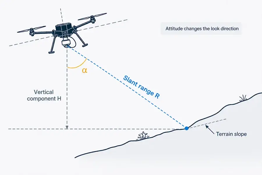
If (α) is the angle between the measured look direction and the local vertical, the vertical separation between the sensor and the illuminated terrain point is:
H = R cos α
This simple relationship is useful, but it does not solve the complete airborne measurement problem.
- If the module points exactly to local nadir, (α) approaches zero and (H) approaches (R).
- If the platform rolls or pitches while the module is fixed to the airframe, the look direction changes with the platform.
- If a gimbal points the module away from nadir, the gimbal angle belongs in the transformation.
- If the beam hits a slope away from the point directly beneath the platform, (H) is the vertical separation to the illuminated point, not necessarily the platform’s height above the terrain directly below it.
- If the required output is elevation, the system must also know the sensor position and reference datum.
At small angles, the range-to-height difference may look modest, but angular uncertainty creates a horizontal footprint shift and can become an important vertical error over sloped terrain. The error budget must include IMU attitude quality, rangefinder-to-IMU mounting angle, gimbal or encoder angle, structural flex, and timing alignment.
From one range value to a surface point
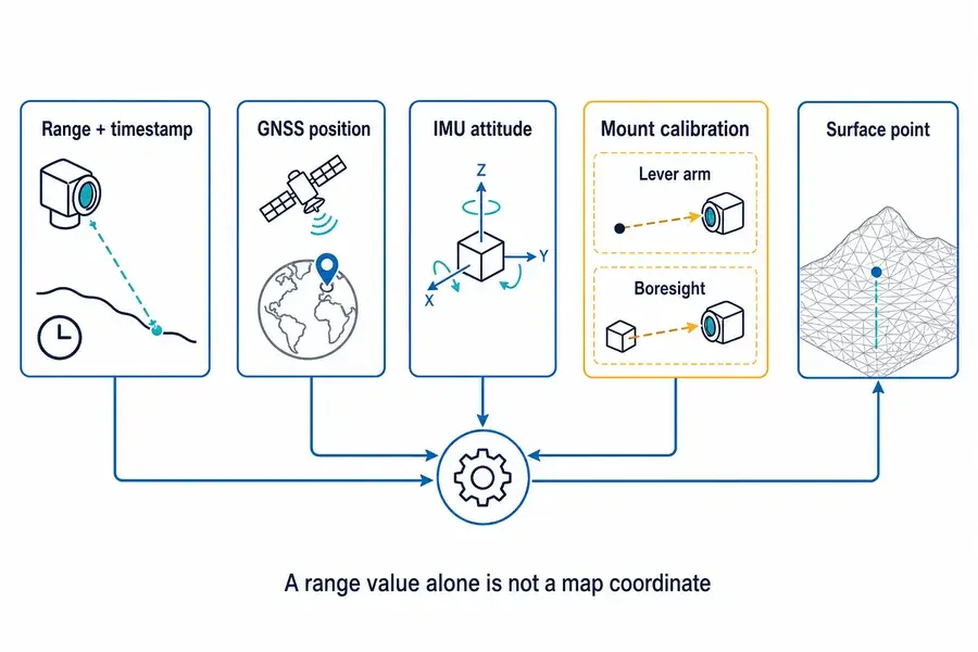
Measurement principle
Connect the optical measurement to system geometry
Signal-flow diagram showing range and timestamp, GNSS position, IMU attitude, lever arm, and boresight contributing to a surface point.
In a simplified mapping frame:
psurface = psensor + Rulook
where:
- (psensor) is the sensor optical-center position in the mapping frame;
- (R) is the measured slant range;
- (ulook) is a unit vector describing the measurement direction in the same frame;
- (ptarget) is the illuminated surface point.
The difficult term is usually (ulook). It must be derived from:
- the rangefinder’s optical axis;
- its fixed boresight rotation relative to the IMU or payload frame;
- any gimbal or scanner angle;
- the platform roll, pitch, and heading at the measurement time;
- the chosen local or global coordinate convention.
The sensor position also needs more than a GNSS coordinate. The offset from the GNSS/IMU reference point to the rangefinder optical center—the lever arm—must be measured in a defined body frame and transformed with attitude. NOAA airborne data workflows and published UAS-LiDAR studies identify GNSS/IMU processing, lever-arm offsets, boresight calibration, overlapping lines, and timing as core parts of georeferencing.12
Time synchronization is a geometric parameter
On a moving platform, a range sample with the wrong timestamp is assigned the wrong position and orientation. A useful interface specification should therefore cover:
- when the range timestamp is created;
- whether it represents trigger, emission, detection, or packet transmission;
- host and module clock behavior;
- command-to-measurement latency and variation;
- serial transport delay;
- GNSS time or pulse-per-second synchronization strategy;
- how invalid, stale, or missed measurements are marked.
For point measurement, log the raw range, validity state, module time, host receipt time, platform position, platform attitude, gimbal angle, and configuration revision. Preserve enough information to recalculate coordinates after calibration improves.
Surface return decides whether the distance is useful
Measurement response
Interpret the optical response in application context
Comparison of diffuse ground, vegetation, smooth water, and oblique-surface return conditions for airborne ranging.
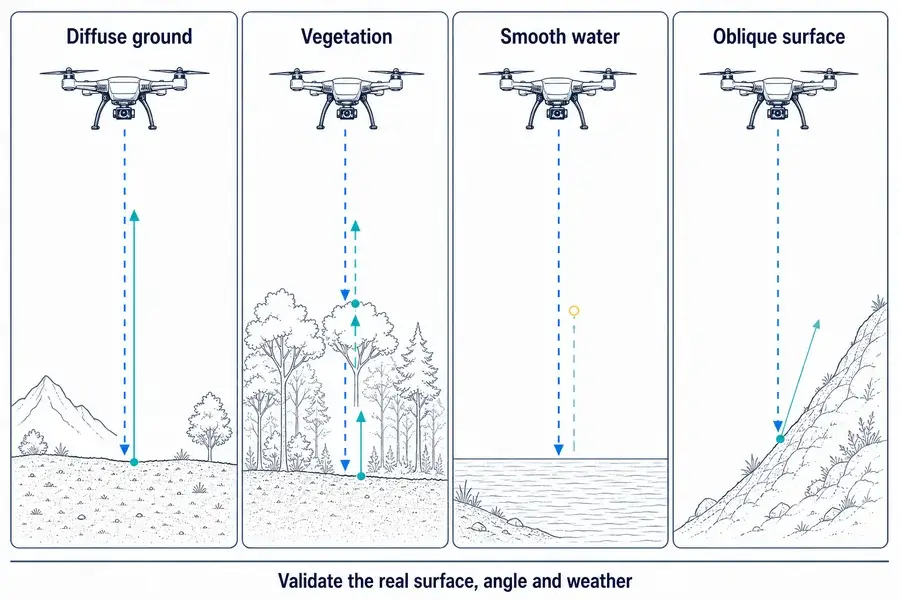
Diffuse ground and civil structures
Dry soil, rock, concrete, painted surfaces, and roofing can return different amounts of energy at 1535 nm. Texture, moisture, contamination, and incidence angle matter. Do not apply a visible-color judgment such as “light surfaces always range farther” without wavelength-specific validation.
Vegetation
A single pulse may interact with a canopy, branches, understory, and ground. A module with multi-target or first/last-return logic can provide useful options, but a 1–10 Hz single-point channel is not a substitute for a waveform-resolving or high-density scanning instrument when canopy structure is the product requirement. USGS airborne research shows why first surface, last surface, and full-waveform methods answer different vegetation questions.3
Smooth water and wet surfaces
Near-infrared and short-wave-infrared ranging should not be presented as bathymetric measurement. Water absorption, surface angle, wave state, turbidity, and specular reflection can produce weak, intermittent, or missing returns. Green bathymetric LiDAR uses a different wavelength strategy for water penetration.4
Oblique slopes and structure faces
An oblique surface can redirect much of the reflected energy away from the receiver. The projected footprint also stretches across the surface, and range can vary across that footprint. Validate the maximum incidence angle expected in the real trajectory, not only a perpendicular panel on the bench.
Atmosphere and external window
Fog, rain, dust, aerosols, condensation, and contamination reduce the useful return or create unwanted near backscatter. Loss occurs on both the outgoing and returning paths. Test the complete payload with its final external window; a bare-module bench result does not include window transmission, internal reflection, contamination, or enclosure alignment.
Beam divergence determines the ground footprint
For a far-field estimate using full-angle divergence:
d ≈ Rθ
where (d) is approximate spot diameter, (R) is slant range, and (θ) is full-angle divergence in radians.
Examples:
- at 500 m, 0.6 mrad corresponds to an approximate 0.30 m spot;
- at 1,000 m, 0.6 mrad corresponds to an approximate 0.60 m spot;
- at 1,000 m, 0.3 mrad corresponds to an approximate 0.30 m spot.
These are geometric estimates, not acceptance values. Initial beam diameter, beam profile, focus, optical aberration, turbulence, vibration, and beam wander are omitted.
For terrain-height measurement, a larger footprint can average or mix returns from vegetation, rocks, roof edges, or sloped ground. For camera-assisted point measurement, a narrower beam can improve target fill, but it also demands tighter camera-to-laser alignment and more stable pointing.
At an oblique incidence angle (β), the footprint stretches along the surface. In an ideal geometric approximation, the long dimension increases roughly as (1/cosβ). Real return behavior also depends on surface scattering and receiver geometry, so use this only as a design cue.
Why 1535 nm is useful—and what it does not guarantee
A 1535 nm rangefinder commonly combines an erbium-glass pulsed source with a receiver designed for the 1.5 μm band. This architecture can support compact long-distance measurement and offers a different ocular-interaction regime from shorter near-infrared wavelengths.
However:
- wavelength does not establish the laser class of the finished payload;
- laser safety depends on accessible emission, pulse properties, repetition, aperture, divergence, exposure geometry, protective housing, and the applicable test method;
- a host optical window can change the accessible beam;
- a module statement must not be transferred automatically to the integrated product.
Lumexis should publish a formal laser-class claim only when the exact production configuration has supporting compliance documentation.
Integration checklist for a civil airborne payload
Mechanical mounting and boresight
- Define the module optical-center and optical-axis datums.
- Mount to a stiff, repeatable payload structure without distorting the optics.
- Measure the lever arm from the navigation reference point to the optical center.
- Calibrate the boresight rotation between the rangefinder and IMU, camera, or gimbal frame.
- Check alignment before and after vibration and temperature exposure.
- Route cables so they do not apply changing torque to the module or mount.
Vibration and platform motion
The measurement path must remain on the intended surface during emission and reception. Review:
- rotor-related vibration and structural resonances;
- gimbal stabilization bandwidth;
- rolling-shutter camera timing if range is paired with an image;
- attitude interpolation at the range timestamp;
- motion blur and feature movement in the camera;
- structural flex between the navigation sensor and rangefinder.
A vibration rating in a component specification does not prove coordinate accuracy after integration. The payload must verify both functional survival and retained alignment.
Power
- Size the rail for peak power, not only the average value.
- Verify voltage at the module during emission, including cable and connector drop.
- Characterize startup, enable, standby, and continuous-ranging states.
- Check whether switching noise affects the IMU, GNSS receiver, camera, or radio.
- Log supply voltage and current during ground and airborne testing.
Communication
Lumexis platforms support RS422 or TTL according to configuration.
- RS422 is useful when cable length and electrical noise justify differential signaling.
- TTL requires confirmed logic levels, common ground, cable length, and host compatibility.
- Confirm the controlled protocol revision, baud rate, command framing, timeout, enable behavior, and error codes.
- Define what the host does after invalid range, timeout, out-of-range return, or communication loss.
Optical window and baffle
The host window is part of the optical system.
- Use material and coating with verified transmission around 1535 nm.
- Provide separate clear apertures for transmit and receive paths when required by the selected module.
- Keep the window close enough to avoid clipping while respecting mechanical tolerance.
- Tilt and baffle the window only after evaluating ghost returns and axis shift.
- Control condensation, dust, water film, scratches, adhesive overflow, and coating damage.
- Recheck maximum and minimum range with the final window and enclosure.
Thermal environment
Airborne enclosures experience solar load, airflow, internal heat, rapid altitude changes, and cold soak. Verify:
- module case temperature, not only ambient air;
- alignment drift between the rangefinder, IMU, and camera;
- startup time after cold soak;
- supply behavior and measurement validity across temperature;
- condensation risk during transitions.
Ground and airborne validation plan
1. Bench integration
- verify power, enable, commands, response framing, and fault handling;
- confirm timestamp behavior and measurement latency;
- establish module-to-payload datums;
- test representative diffuse targets beyond the specified minimum range;
- use controlled procedures for close or highly reflective surfaces.
2. Outdoor ground test
- install the final window, baffle, mount, cable, and power system;
- measure known targets with different material, size, angle, and distance;
- test background light and expected visibility conditions;
- compare first, last, and multi-target behavior where available;
- record invalid and missing returns instead of filtering them silently.
3. Static pointing and calibration
- survey reference surfaces or targets;
- measure lever arms in the chosen body frame;
- determine camera/rangefinder and rangefinder/IMU boresight;
- verify optical-axis stability after handling and thermal cycling;
- lock the coordinate definitions and sign conventions.
4. Low-risk airborne engineering test
- begin over a controlled, open civil test area with simple surfaces;
- log raw range, timestamp, GNSS, attitude, gimbal angle, power, and validity;
- compare opposite-direction and crossing passes over common surfaces;
- examine range dropouts over vegetation, water, edges, and slopes;
- check whether data latency or attitude interpolation creates spatial offsets.
5. Acceptance test
Define pass/fail criteria for:
- valid-measurement rate by surface and distance;
- range bias and repeatability;
- vertical-height or point-coordinate error after the full transformation;
- boresight stability before and after environmental exposure;
- invalid-reading behavior;
- power, thermal, and communication margin.
The acceptance metric should match the output promised to the customer. A ±1 m module range specification and a finished-system vertical or coordinate accuracy are different quantities.
What to send Lumexis for a module recommendation
Copy this checklist into your enquiry:
- application: terrain height, civil structure standoff, point measurement, or surface profiling;
- required output: slant range, vertical height, relative clearance, or surface coordinate;
- normal and maximum sensor-to-surface distance;
- minimum distance during takeoff, handling, or close inspection;
- surface types, reflectivity estimate, slope, vegetation, moisture, and expected angle;
- platform type and maximum roll, pitch, angular rate, and vibration environment;
- available module dimensions, mass, receive aperture, and mounting orientation;
- average and peak-power limits and supply voltage;
- required rate, latency, timestamp accuracy, and data logging format;
- GNSS, IMU, camera, gimbal, scanner, or encoder already in the payload;
- RS422 or TTL preference and cable length;
- optical-window material, coating, thickness, position, and clear apertures;
- operating temperature, humidity, contamination, and weather envelope;
- prototype quantity, annual volume, and target programme timing.
CTA: Discuss a civil UAV laser ranging solution with Lumexis
Lumexis — precision laser sources, engineered for the real world.
Frequently asked questions
Can a laser rangefinder module measure UAV altitude?
It measures slant range to the illuminated surface. When the measurement direction is known relative to local vertical, the system can calculate the vertical separation to that surface point. Height above the terrain directly below the platform may require additional terrain geometry when the beam is off nadir.
Is a laser rangefinder module the same as a laser altimeter?
A laser altimeter is a system configured to derive height or surface elevation from laser range. A rangefinder module provides the distance channel; the host may need attitude, position, mounting calibration, timing, and surface logic to turn that channel into altimetry.
Can one Lumexis module create a 3D map?
Not by itself. A single-point module measures along one look direction at a time. A host can combine repeated range samples with known angles and platform pose, but dense mapping usually requires a scanning LiDAR architecture with much higher sampling density.
Which Lumexis model is best for a lightweight civil UAV?
Start with the smallest module whose verified target and environmental conditions cover the real slant-range envelope. In the current platform table, the 1535-LXCJ0300 has the lowest listed mass at 33 ± 1 g. Selection still depends on surface return, minimum range, pointing, power, and integration margin.
Why can the range be valid while the calculated height is wrong?
The module may measure the slant distance correctly while the host applies the wrong attitude, timestamp, gimbal angle, lever arm, boresight, or coordinate convention. Range accuracy and georeferencing accuracy belong to different parts of the error budget.
How do roll and pitch affect laser altimetry?
They rotate a body-fixed measurement direction away from local vertical. The host must use the platform attitude at the measurement time. On sloped terrain, an angular error can also move the illuminated point horizontally to a different surface elevation.
What happens over vegetation?
The pulse may return from the canopy, branches, understory, or ground. First/last or multi-target functions can help identify different returns, but a low-rate single-point module does not provide the same canopy information as a full-waveform or dense scanning instrument.
Will 1535 nm measure through water?
Do not specify a 1535 nm module as a bathymetric sensor. Water absorption and surface reflection can lead to weak or missing returns. Water-penetrating LiDAR generally uses a different wavelength strategy and system architecture.
What should be retested after adding the payload window?
Retest minimum and maximum working distance, target-specific valid-reading rate, boresight, background-light behavior, temperature, contamination, and ghost-return behavior with the final window, baffle, mount, cable, and power system.
Is 1535 nm automatically safe in the finished payload?
No. Wavelength is only one input. Finished-product classification depends on accessible emission and the applicable measurement method. A formal claim requires evidence for the exact production configuration.
Technical references
External technical and application sources
Additional application context
- U.S. Geological Survey, “What Is LiDAR?,” Time-of-Flight point measurement and airborne scanning context.
- U.S. Geological Survey, “The Feasibility of Using Lidar-Derived Digital Elevation Models for Gravity Data Reduction,” laser scanner, GNSS, and IMU as the main airborne collection components.
- NASA Airborne Science Program, “Land, Vegetation and Ice Sensor,” full-waveform laser altimetry, camera integration, and surface-structure applications.
- ASPRS, “Quality Assurance and Quality Control of LiDAR Systems and Derived Data,” mounting parameters, GNSS/IMU direct georeferencing, and laboratory, platform, and in-flight calibration.
- NIST, “User’s Manual for Lidar Target Simulator,” round-trip Time-of-Flight range equation.