

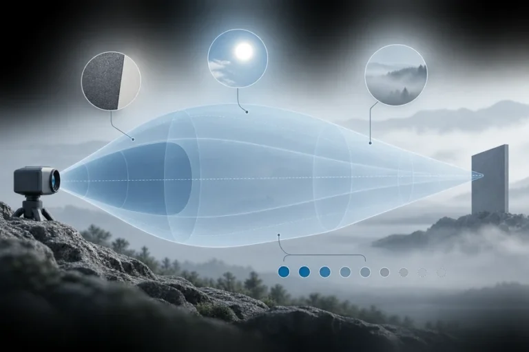

Laser rangefinder boresight alignment can look correct on an open bench and shift after the module is fastened into its enclosure. Clamp load, cable pull, window installation, temperature, and fixture repeatability can all move the optical axis relative to the host reference.
That movement may appear as a missed target, inconsistent range, or disagreement with a camera or sighting channel. Treating it as a software offset alone leaves the mechanical cause in place.
Laser rangefinder boresight alignment should be designed as a controlled relationship between the module optical axis, the host datum system, and the final line of sight. Use repeatable locating features, separate location from clamping, limit preload and cable forces, then verify alignment after full assembly and environmental exposure with a released fixture and acceptance method.
Define the alignment relationship before designing the mount
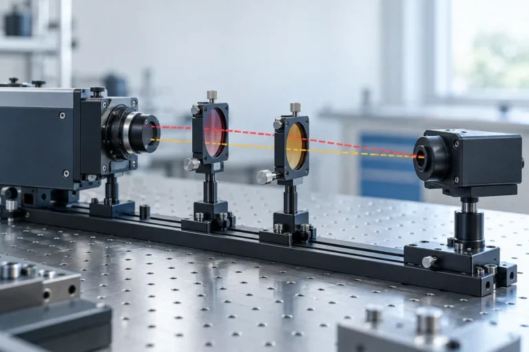
Boresight is not one universal axis. An integrated system may need to control the transmitter relative to the receiver, the module relative to its mechanical references, and the completed rangefinder relative to a camera, telescope, scanner, or machine coordinate system. Write each required relationship down before selecting screws or brackets.
ISO 10110-6 distinguishes an optical axis, datum features, a datum axis, tilt, and lateral displacement. This separates the ideal relationship from the imperfect physical surfaces used to establish it.

Define at least four items in the interface control document:
- the host reference frame and accessible datum features;
- the module reference features and stated relationship to its optical axis;
- the permitted angular and lateral error at assembly and after exposure;
- the target distance, setup, and calculation used for verification.
Keep angular error and lateral offset separate. For small angles, target-plane displacement is approximately the angle in radians multiplied by distance. A short-range check can therefore hide a small angular error that becomes important farther away. Lateral offset behaves differently and must be interpreted with the actual geometry.
Our broader laser rangefinder module integration guide places the datum plan beside optical clearance, thermal design, power, communications, and system verification. Those interfaces should be reviewed together because a change in one can disturb the alignment relationship.
Build the mount from deterministic datums
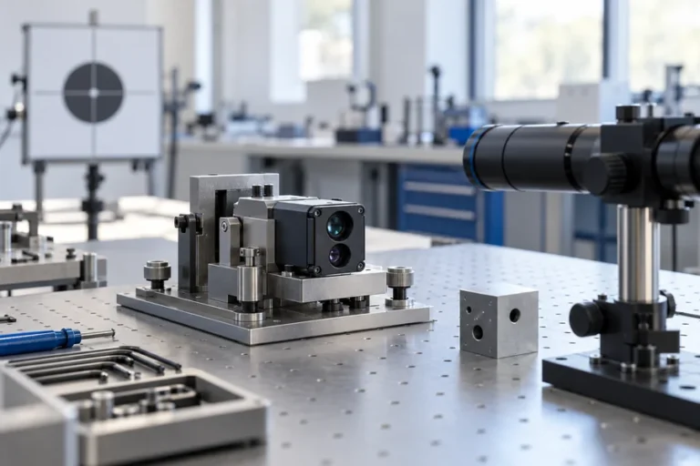
A repeatable mount constrains the necessary degrees of freedom without forcing the module to conform to uncertain surfaces. A practical approach uses a primary seating plane, a secondary feature that controls in-plane rotation or translation, and a tertiary feature that completes location. The exact geometry may use pads, dowels, a shoulder, a bore, or machined edges, but the constraint logic must be explicit.
Separate locating from clamping. Datums establish position; fasteners keep the part seated. A screw should not drag the module sideways into its final location or bend a bracket until the beam appears aligned. That creates torque-dependent results and makes service replacement difficult to repeat.
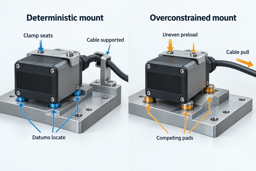
Control the bearing surfaces, fastener sequence and torque, locking method, shim or adhesive location, cable strain relief, and cleanliness under every seating feature.
Overconstraint often enters quietly. Four nominally coplanar hard pads can rock or distort when their height errors compete. A stiff cable can become an unintended spring. A gasket can apply an off-axis load. Adhesive can shrink or cure unevenly. The drawing should show which features locate, which clamp, and which are allowed to float.
Keep the optical window out of the alignment error budget
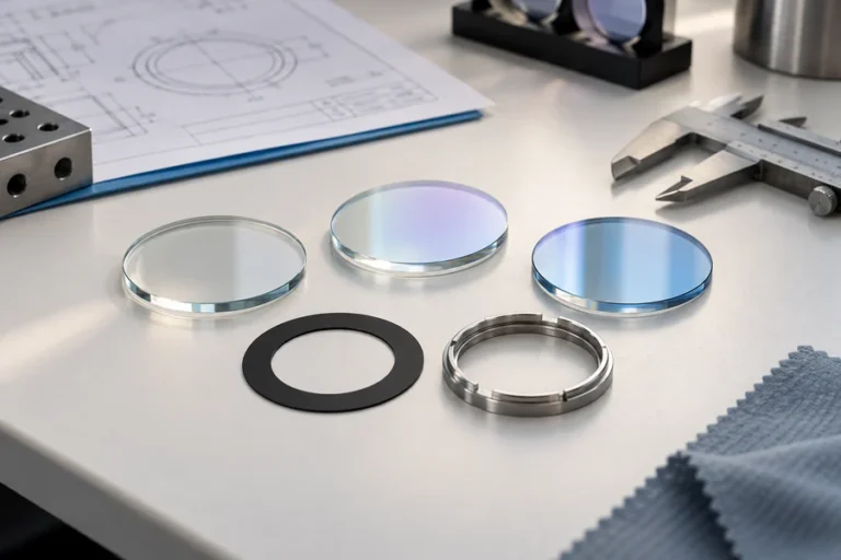
The final optical path includes the enclosure window, not only the module. Window wedge, tilt, mounting stress, coating choice, clear aperture, contamination, and seal compression can change beam direction or add unwanted reflections. Verify the chosen window at the operating wavelength and with the released mechanical stack.
Model the transmitted beam envelope and receiver field across assembly tolerance, temperature, and expected adjustment range. Maintain clearance at the worst combination, not only the nominal CAD position.
Install the production-intent window before final boresight verification. If alignment changes after the window or seal is added, isolate whether the cause is beam deviation, clipping, reflection, enclosure distortion, or a shifted module seat. Our guide to optical crosstalk in rangefinder integration covers reflection paths that can be mistaken for a pointing or range problem.
Manage preload, thermal growth, and cable forces
Fasteners and brackets create a load path. That path should hold the module against its datums without introducing excessive distortion. Define torque from the joint design and hardware rather than copying a value from a different enclosure. Then measure whether the alignment moves during the tightening sequence.
Material expansion can rotate or translate the module when the host, bracket, fastener, window cell, and module housing change temperature at different rates. NASA testing of laser mirror mounts measured angular movement and hysteresis during temperature cycling, while a separate laser-altimeter development documented boresight risk over temperature and the need to preserve transmit-to-receive alignment. The practical lesson is not to copy those architectures; it is to validate the released stack across the required temperature states.
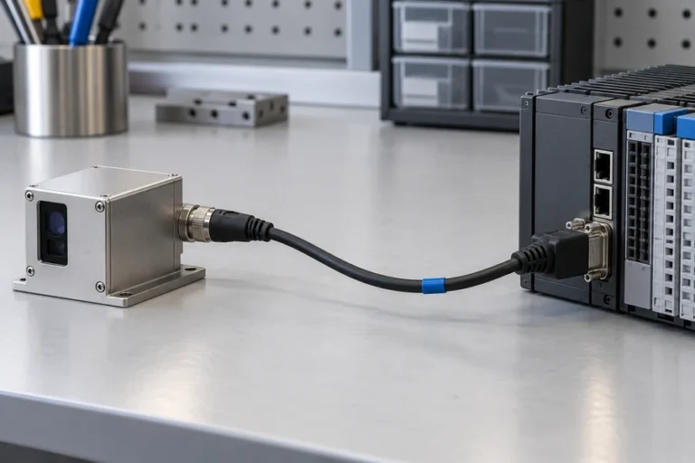
Cable routing deserves the same attention. Support the connector and cable so service loops, harness ties, enclosure closure, or gimbal motion do not pull the module away from its seat. Check alignment with the harness in the final routed condition, not hanging freely on the bench.
Choose a bounded adjustment strategy
Fixed alignment reduces parts and process steps, but it only works when the full stack-up and environmental drift fit inside the error budget.
An adjustable mount can recover build variation, but it adds sensitivity to operator method, locking, backlash, and verification. Give adjustment a limited range and a predictable axis. Avoid mechanisms that couple pitch, yaw, and translation so strongly that each correction disturbs the previous one.
A hybrid approach is often practical: deterministic datums establish a repeatable starting position, a small controlled adjustment removes the remaining bias, and a defined lock preserves the result. Record the adjustment state or shim configuration with the unit. Do not rely on undocumented technician judgment.
Verify the complete assembly, then challenge it
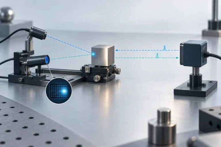
NASA developed a portable target assembly to check active-sensor boresight at the integrated instrument level. The transferable principle is important for OEM work: verify the axis relationship after integration with a stable reference, not only while the module is separate.

Use a target or collimated setup appropriate to the required angular resolution. Define its geometry, fixture datum, module state, range, acquisition method, environment, and calculation. Measure fixture repeatability before judging product repeatability.
The verification sequence should cover:
- initial seating and fastener sequence;
- complete cable, window, seal, and enclosure assembly;
- repeated remove-and-reinstall trials where serviceability matters;
- required temperature states and stabilization criteria;
- applicable vibration, handling, or transport exposure;
- final remeasurement against the same acceptance definition.
Do not “correct” every observed shift immediately. First determine whether it follows the module, host, fixture, window, fastener sequence, operator, or environment. A controlled trial changes one factor at a time and preserves before-and-after records.
Our rangefinder range-test guide explains how to bind performance claims to target, atmosphere, instrument state, and repeated-return criteria. Boresight verification needs the same discipline: conditions and configuration are part of the result.
Transfer alignment into production
The production package should include the datum scheme, drawing tolerances, released hardware, torque and sequence, allowable shims or adjustment limits, window and seal configuration, cable routing, fixture definition, calibration method, pass criteria, and recheck triggers. Configuration changes must return to the alignment error budget.
LUMEXIS designs and manufactures laser sources and modules through our Wuxi engineering and commercial office and 14,000-square-meter Taizhou manufacturing base. Our team can support optomechanical interface review, test-method development, temperature cycling, assembly controls, and final verification through OEM engineering services.
For teams evaluating a compact module, the 1535 nm 7 km laser rangefinder module is one current product reference. Final mounting tolerances and alignment acceptance still need to match the selected configuration and host system. Standard products can ship within three days when confirmed available; custom and private-label programs use project-specific requirements and lead times.
Frequently asked questions
What is the difference between boresight error and range accuracy?
Boresight error describes where the module points relative to a defined reference axis. Range accuracy describes how closely the reported distance matches the defined distance under stated conditions. A system can report an accurate distance to the wrong object if its pointing relationship is not controlled.
Can software compensate for laser rangefinder boresight alignment error?
Software can correct a stable, measured offset within the system model. It cannot make a loose datum, changing cable force, window stress, or thermal drift stable. Remove or bound the mechanical variation first, then use calibration for the remaining repeatable bias.
Should boresight be checked before or after the optical window is installed?
Use an early check to catch module or fixture problems, but make final acceptance after the production-intent window, seal, cable, and enclosure are installed. These parts can change alignment, clipping, reflection, or structural load.
How far away should the alignment target be?
The distance must make the required angular change measurable while keeping the target, spot, receiver response, and fixture stable. A collimated setup can simulate a far target when appropriate. State the geometry and calculation so the same acceptance method can be repeated.
When should boresight be reverified?
Reverify after any change that can alter the mechanical or optical stack: module removal, mount or fastener change, window or seal change, cable rerouting, enclosure revision, significant environmental exposure, fixture repair, or a supplier process change affecting reference features.
References
- ISO, ISO 10110-6:2025 — Optics and photonics: centring and tilt tolerances.
- NASA, A Boresight Adjustment Mechanism for Use on Laser Altimeters.
- NASA, Angular Alignment Testing of Laser Mirror Mounts Under Temperature Cycling.
- NASA, Target Assembly to Check Boresight Alignment of Active Sensors.
Planning an OEM integration? Send our applications engineers the selected module or wavelength, host datum drawing, mounting stack, window, cable route, operating environment, target geometry, required pointing tolerance, interface, and expected volume. We can recommend a standard configuration or review the mechanical and verification inputs for a custom or private-label project.