
Laser Source Technologyfor OEM Systems.
Lumexis develops the optical, electronic, thermal and manufacturing technologies behind laser rangefinder modules, fiber coupled lasers, LiDAR laser sources and erbium-glass laser sources. We connect source physics to system integration and repeatable production.
 LiDAR · infrastructure metrology
Laser Technology for OEM Photonics Systems.
A useful laser source is more than a wavelength and a power value. Its pulse behavior, beam delivery, receiver chain, interfaces, thermal path and package must work together inside the customer’s system.
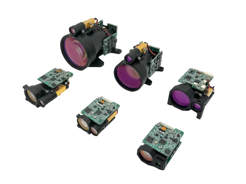
Pulsed TOF ranging
Nanosecond pulse timing, optical transmit and receive paths, echo detection and range calculation.
Read the principle → 02 / GenerateErbium-glass pulse sources
Compact diode-pumped solid-state sources engineered around 1535 nm nanosecond output.
Explore the source → 03 / DeliverFiber coupling and wavelength control
Beam conditioning, active alignment, fiber-interface control and optional spectral stabilization.
Follow the optical path → 04 / Amplify1.5 µm pulsed fiber sources
Short-pulse generation, controlled repetition rate, fiber delivery and timing-reference integration.
See the architecture → 05 / DetectReceiver and control electronics
APD-based echo reception, low-noise amplification, timing logic and host-system communication.
Trace the signal → 06 / PreservePackaging and verification
Thermal design, precision assembly, sealing, aging and environmental performance checks.
See the process →Pulsed Time-of-Flight Technology for Laser Rangefinder Modules.
A pulsed laser rangefinder measures the round-trip flight time of light. The equation is simple. Producing a useful answer across changing targets and environments is the real engineering task.
Range = speed of light × round-trip time / 2The transmitter launches a short optical pulse. Receiver optics collect a small fraction of the reflected energy, an avalanche photodiode converts it into an electrical signal, and high-speed timing electronics estimate the interval between emission and return.
Energy and pulse width
For a given pulse energy, shorter pulses produce higher peak power. The useful balance depends on the target, receiver bandwidth, repetition strategy and system constraints.
Divergence and target coverage
Beam divergence controls spot size with distance. A smaller spot can improve energy density on compact targets, but pointing, alignment and field-of-view tolerances must remain practical.
Receiver aperture and noise
A larger effective aperture collects more return light. Detection performance still depends on optical transmission, detector gain, analog bandwidth, ambient background and threshold strategy.
Atmosphere and target reflectance
Visibility, wavelength-dependent attenuation, target size, surface reflectance and incidence angle all influence the echo that reaches the receiver.
Maximum range is not a single-component property. It is the result of the complete link budget, including the source, beam, target, atmosphere, receiver and signal-processing chain.
1535 nm Erbium-Glass Laser Technology.
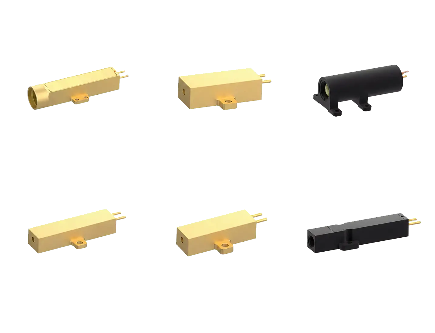
Erbium-doped glass provides a solid-state gain medium in the 1.5 µm spectral region. Lumexis integrates the pump source, gain medium, resonator, package and drive conditions as one compact pulse-source platform.
Diode pump · erbium glass · nanosecond outputThe engineering objective is to convert a controlled electrical drive pulse into repeatable optical energy while keeping the source compact enough for integration into a laser rangefinder module or scientific instrument.
Pump-to-gain matching
The semiconductor pump, erbium-glass absorption and drive pulse must be matched so stored energy builds efficiently without unnecessary thermal load.
Nanosecond pulse formation
Resonator and loss-control design release stored energy as a short pulse. Pulse energy, width, repetition rate and beam quality are treated as linked parameters.
Optomechanical stability
Sub-millimeter optical elements and interfaces need controlled placement, bonding and contamination management to preserve alignment and output consistency.
Electrical protection and drive control
Laser-diode current must be controlled without overshoot or surge. Electrostatic handling, clean optical surfaces and reliable heat transfer remain part of the source design.
Wavelength, pulse energy, pulse width, repetition rate, beam quality, divergence, electrical drive and mechanical envelope are balanced against the requirements of the finished system.
Fiber Coupling and Wavelength Control for Diode Lasers.
Fiber coupling converts the asymmetric output of one or more diode emitters into a defined fiber interface. The result is a source that can be routed, integrated and serviced more predictably.
Beam conditioning · active alignment · fiber deliveryHigh coupling efficiency depends on matching the emitter’s optical phase space to the fiber core and numerical aperture. That requires beam shaping, alignment control, stable fixation and a thermal structure that does not pull the optical path out of position.
Core diameter and numerical aperture
Fiber core and NA determine the acceptance space for the focused beam. They also influence delivered brightness, bend sensitivity and downstream optics.
Active alignment
Coupling is optimized while optical power is monitored. Automated alignment helps find and hold the highest-value position before the assembly is fixed.
Optional wavelength stabilization
Selected pump-source configurations use spectral locking to narrow the output and reduce wavelength movement with current or temperature, supporting absorption-sensitive pumping.
Back-reflection and interface management
Connector condition, end-face cleanliness, return-light exposure, bend radius and conductive cooling are reviewed as part of the installed optical path.
A controlled fiber interface reduces free-space alignment work inside the customer’s instrument and makes wavelength, power, fiber core, connector and package choices easier to specify together.
1.5 µm Pulsed Fiber Laser Technology for LiDAR.
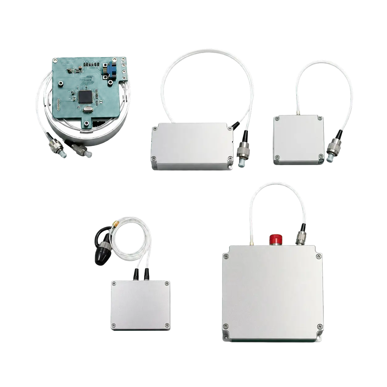
Lumexis 1.5 µm pulsed fiber laser platforms combine pulse generation, fiber amplification, monitoring, trigger control and thermal design in compact integration-ready formats.
1.5 µm band · external trigger · reference outputA pulsed fiber source separates pulse definition from power scaling. The pulse is formed at low power, amplified through a controlled fiber path and delivered through a stable output interface. Actual optical topology is selected by model and performance target.
Peak power and average power
Pulse width, repetition rate and pulse energy jointly determine peak and average power. Raising one parameter can change thermal load, gain saturation and nonlinear behavior elsewhere.
Spectral and nonlinear control
Gain distribution, fiber length and operating point are engineered to keep amplified spontaneous emission and nonlinear distortion within the model’s defined limits.
Trigger and timing reference
External differential triggering and a reference optical output can align emission with scanning, acquisition or ranging electronics while supporting delay characterization.
Conductive thermal path
Stable output requires a defined mounting surface, even clamping force and a low-resistance thermal path into the customer’s enclosure or cold plate.
Fiber delivery, electronic control and reference timing reduce the number of separate functions an OEM team must assemble around the optical source.
Laser Rangefinder Receiver Electronics and Interfaces.
The receiver and control chain links optical performance to the host system. It must resolve weak signals, survive strong returns and communicate predictably under real operating conditions.
APD · analog front end · timing · UART / TTL / RS422In a rangefinder, the electronics define when a pulse is launched, how a return is recognized and how a range value is reported. Detector gain, front-end bandwidth, timing resolution and threshold logic are engineered as one signal chain.
APD echo reception
An avalanche photodiode provides internal gain for weak optical returns. Bias and gain settings must account for temperature, noise, background light and the expected echo range.
Analog dynamic range
The front end must detect distant weak echoes while avoiding saturation or damage from unexpectedly strong close reflections. Optical and electronic protection strategies are considered together.
Timing and calibration
Resolution is influenced by pulse shape, detector bandwidth, comparator behavior, clock resolution and fixed delays. Calibration maps the measured interval to the physical optical path.
Host-system communication
Serial interfaces and defined command sets support ranging control, status reporting and secondary development. Interface level and protocol are confirmed for each model.
Optical windows, ground strategy, supply quality, connector seating, communication level and mechanical mounting all affect the measured result. Interface review begins before the module is installed.
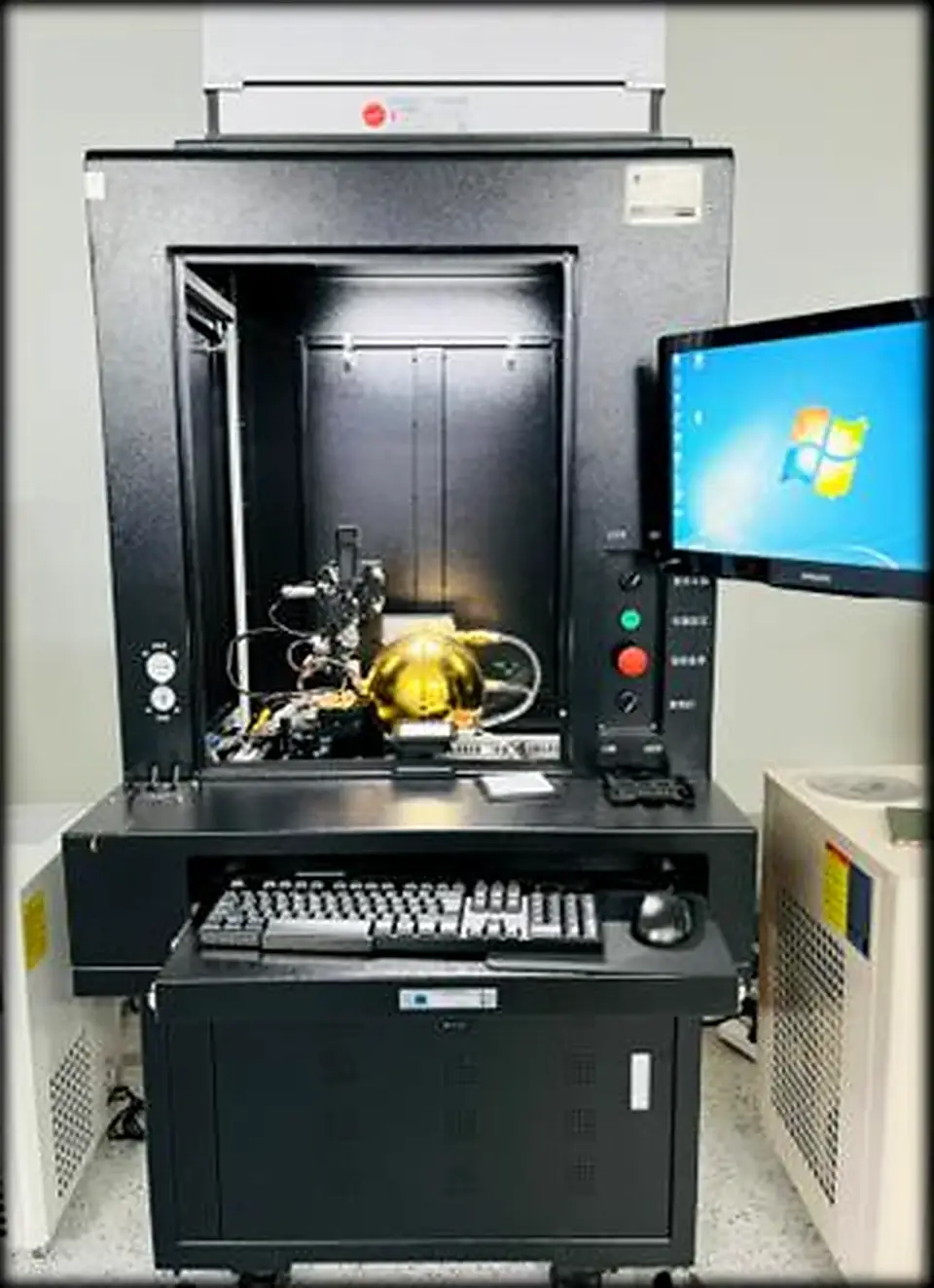
Precision Laser Packaging and Reliability Testing.
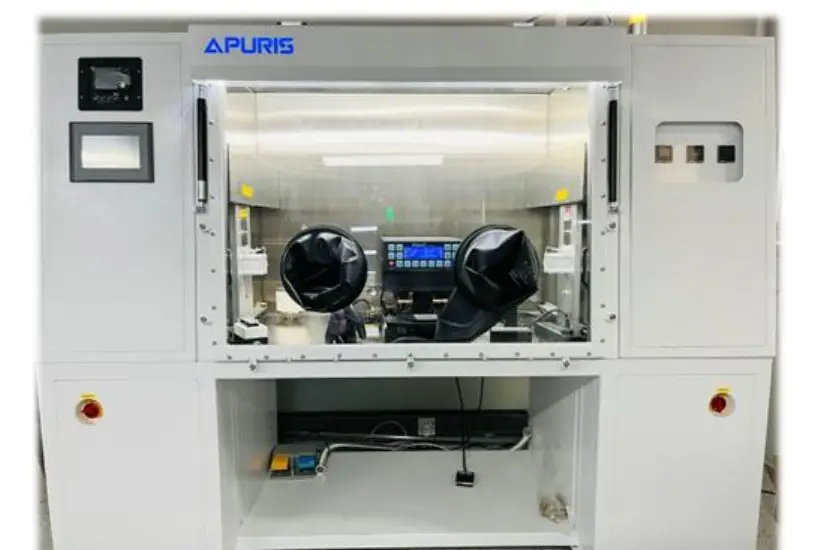
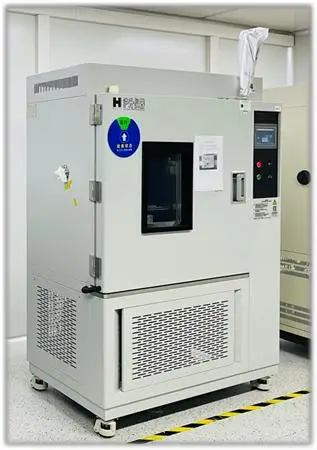
Precision packaging holds the optical path, removes heat, protects sensitive interfaces and turns a laboratory result into a repeatable product. Verification closes the loop between design intent and production output.
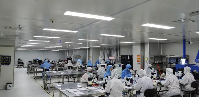
Thermal path first
Junction temperature, mounting flatness, interface material and clamping force influence output, wavelength and operating life. Heat removal is part of the optical design.
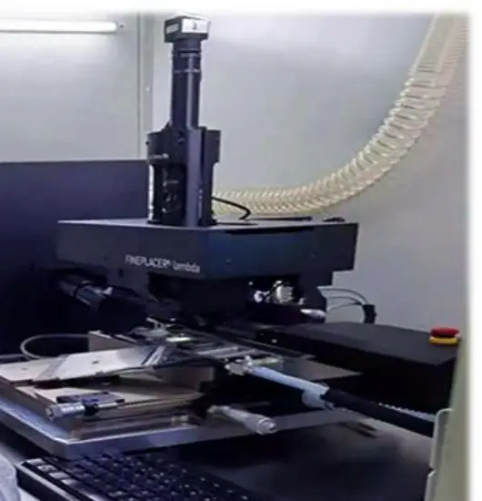
Micron-scale placement
Die bonding, optical alignment and fiber coupling establish the geometry that determines beam delivery and efficiency.
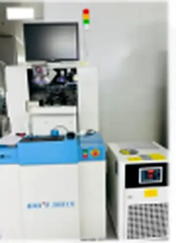
Protected interconnects
Wire bonding, reflow and package sealing create stable electrical, mechanical and environmental interfaces.
Measure, screen, verify
Optical characterization, aging, temperature cycling, dimensional inspection and final performance checks identify variation before release.
Laser Source Specifications, Safety and OEM Integration.
Model-specific performance
Wavelength, output, pulse, environmental range and interface values must be confirmed against the current datasheet and order-specific documentation.
System-level results
Ranging distance, accuracy, optical efficiency and thermal stability depend on both the source and the way it is integrated into the finished system.
Laser safety and compliance
Laser classification and regulatory status are product- and configuration-specific. Use the applicable test report, label and integration instructions rather than a wavelength-only assumption.
OEM review
Lumexis engineers review optical, electrical, thermal, mechanical and interface requirements together before recommending a standard platform or an OEM laser source configuration.
Choose the Right Laser Source Technology for Your System.
Share the wavelength, pulse or power target, optical interface, envelope, operating conditions and qualification plan. We will help define a practical source architecture and integration path.
Lumexis — precision laser sources, engineered for the real world.