1535 ± 5 nm classification for the defined module configuration.

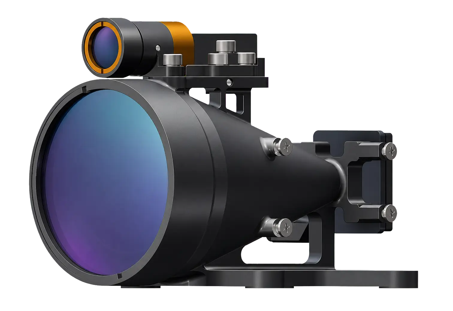
Lumexis develops and manufactures a 1535 nm Class 1 eye-safe laser rangefinder module series built around Er:Glass pulsed sources, transmit and receive optics, single-pulse TOF processing, and TTL or RS422 communication. Specified performance spans ≥3.2–15 km on a 2.3 × 2.3 m target and up to ≥20 km on a large target, with ≤±1 m or ≤±1.5 m accuracy, adjustable 1–10 Hz measurement, DC 5–28 V input, and packages from 33 ± 1 g. Compact size, standby consumption ≤0.2 W, and model-specific engineering files support integration into civil UAV mapping and altitude measurement, surveying instruments, railway and infrastructure inspection, LiDAR and remote-sensing systems, and scientific instruments.
* Class 1 eye-safe classification applies to the defined module configuration. The completed host product requires laser-safety assessment in its final optical and operating configuration.
1535 ± 5 nm classification for the defined module configuration.
Specified for a large target; up to ≥15 km on a 2.3 × 2.3 m target.
For 3–8 km-class models; ≤±1.5 m for the 10 km and 15 km classes.
Adjustable output for single-shot and continuous ranging modes.
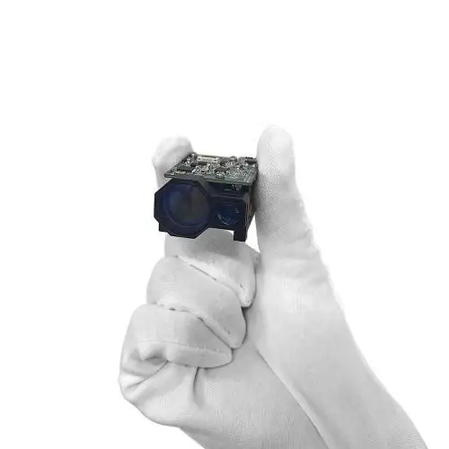
Starting at 48 × 21 × 31 mm and 33 ± 1 g for space-limited integration.
DC 5–28 V input with standby consumption ≤0.2 W.
3–15 km series
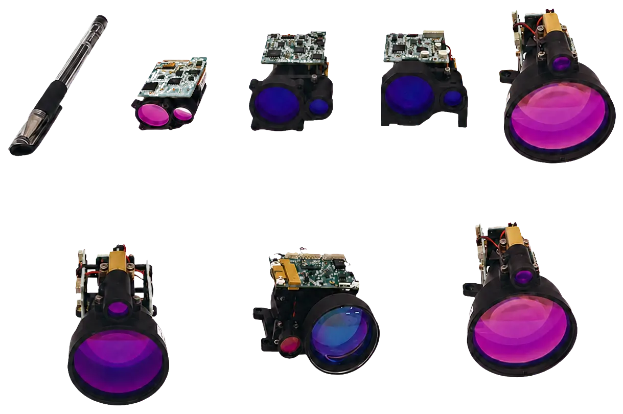
All available models are shown directly below. Compare the intended target and distance first, then check receive aperture, minimum range, mechanical envelope, power demand and host communication before design release.
1535-LXCJ0300
≥3.2 km on a 2.3 × 2.3 m target; ≥5 km on a large target; ≤0.6 mrad divergence.
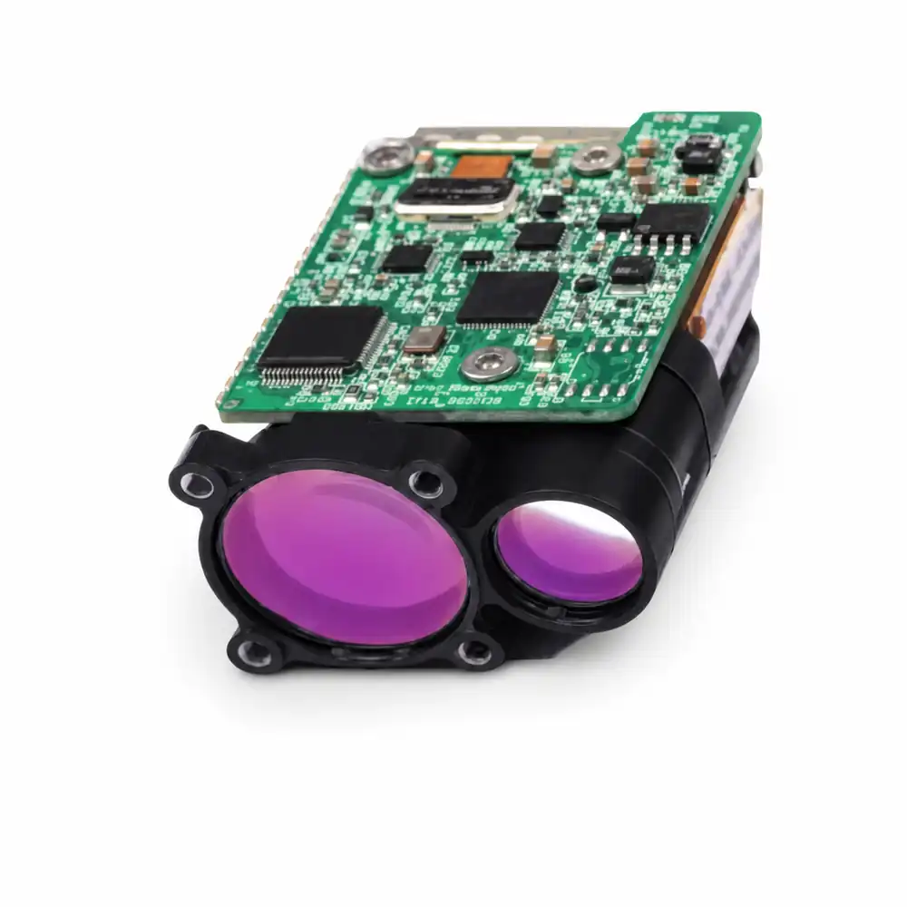
1535-LXCJ0500
≥5 km on a 2.3 × 2.3 m target; ≥6 km on a large target; ≤0.3 mrad divergence.
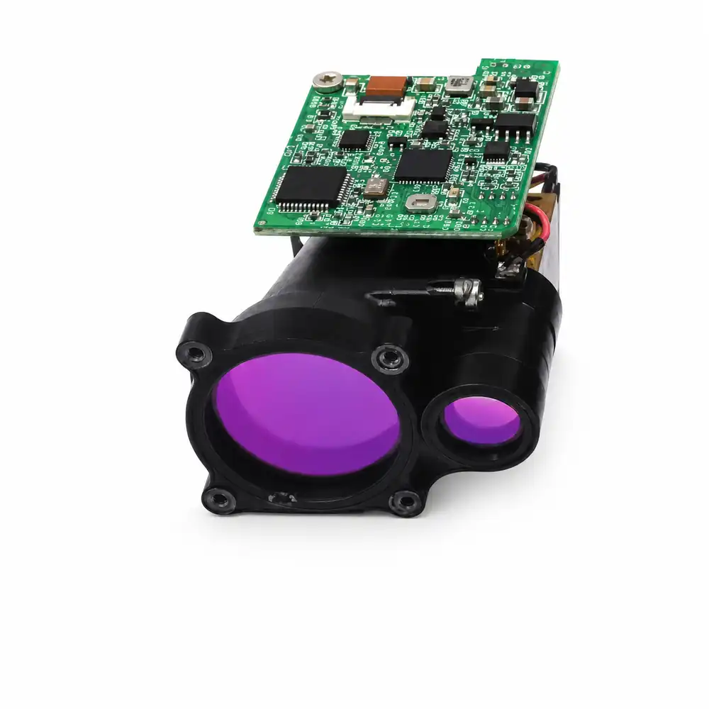
1535-LXCJ0600
≥6 km on a 2.3 × 2.3 m target; ≥7 km on a large target; ≤0.3 mrad divergence.
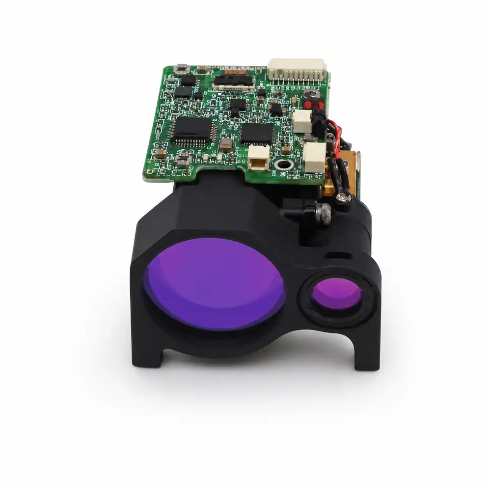
1535-LXCJ0700
≥7 km on a 2.3 × 2.3 m target; ≥8 km on a large target; ≤0.3 mrad divergence.
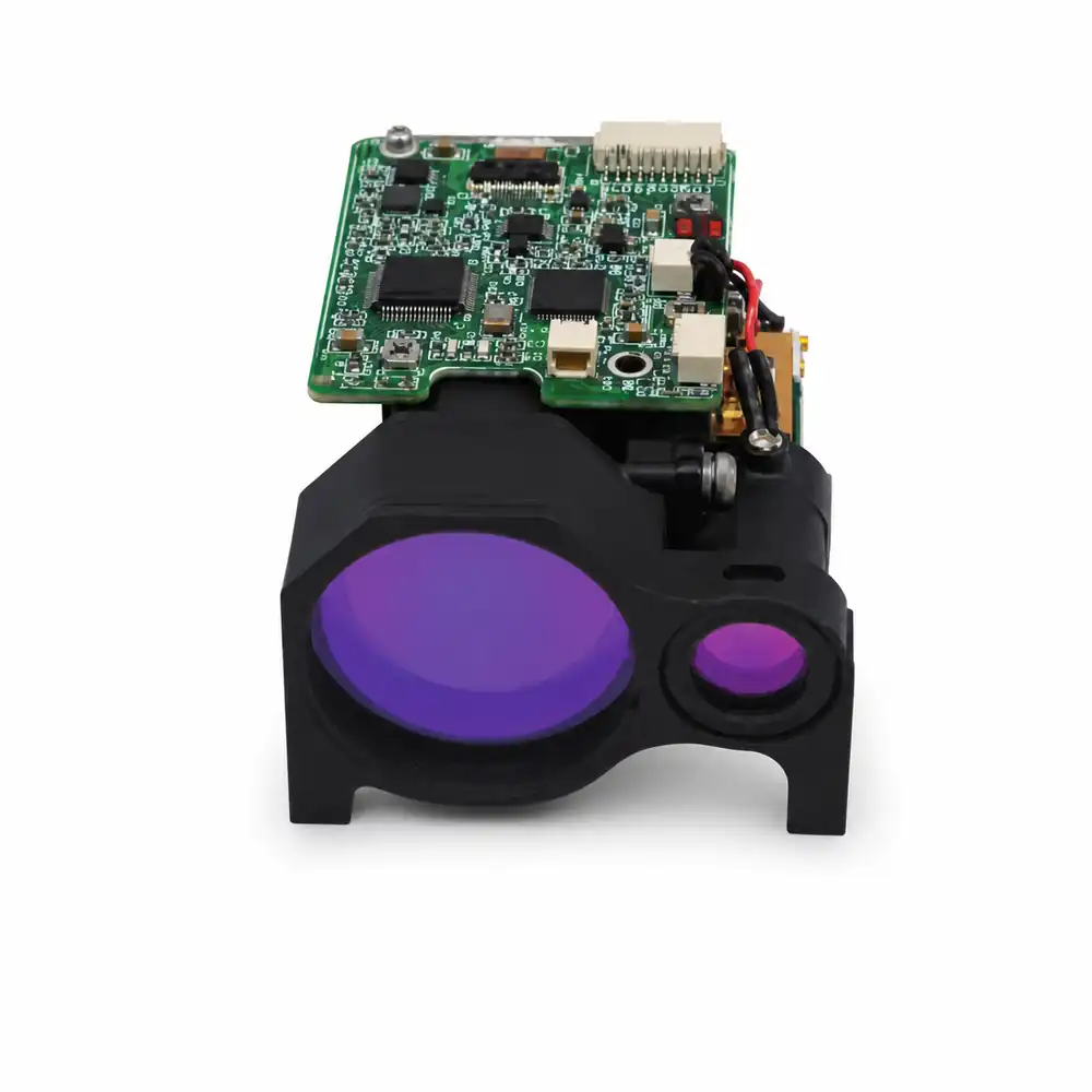
1535-LXCJ0800
≥8 km on a 2.3 × 2.3 m target; ≥10 km on a large target; ≤0.3 mrad divergence.
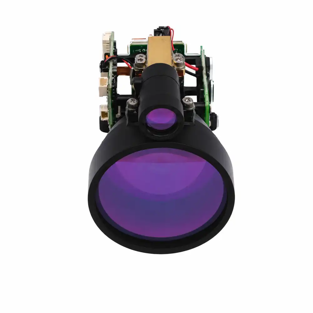
1535-LXCJ1000
≥10 km on a 2.3 × 2.3 m target; ≥12 km on a large target; ≤0.3 mrad divergence.
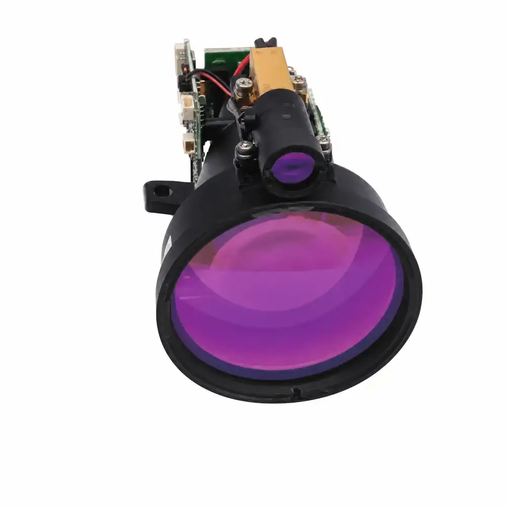
1535-LXCJ1500
≥15 km on a 2.3 × 2.3 m target; ≥20 km on a large target; ≤0.3 mrad divergence.
Single source of specification data
This is the page’s only full specification section. All other sections explain use, integration and delivery without repeating the same parameter set.
| Model | 2.3 × 2.3 m target | Large target | Minimum range | Accuracy | Receive aperture | Dimensions | Weight | Interface | Input | Average power | Operating temperature |
|---|---|---|---|---|---|---|---|---|---|---|---|
| 1535-LXCJ0300 | ≥3.2 km | ≥5 km | ≤15 m | ≤±1 m | 16 mm | 48 × 21 × 31 mm | 33 ± 1 g | RS422; TTL option | DC 5–28 V | ≤0.8 W at 1 Hz | −40 to +70°C |
| 1535-LXCJ0500 | ≥5 km | ≥6 km | ≤15 m | ≤±1 m | 16 mm | 50 × 23 × 33.5 mm | ≤40 g | TTL; RS422 option | DC 5–28 V | ≤1 W at 5 V | −40 to +60°C |
| 1535-LXCJ0600 | ≥6 km | ≥7 km | ≤20 m | ≤±1 m | 21 mm | 65 × 40 × 28 mm | ≤55 g | RS422 | DC 5–28 V | ≤1 W at 5 V | −40 to +60°C |
| 1535-LXCJ0700 | ≥7 km | ≥8 km | ≤30 m | ≤±1 m | 25 mm | 65 × 46 × 32 mm | ≤72 g | RS422 | DC 5–28 V | ≤1 W at 5 V | −40 to +60°C |
| 1535-LXCJ0800 | ≥8 km | ≥10 km | ≤30 m | ≤±1 m | 25 mm | 65 × 46 × 32 mm | ≤72 g | RS422 | DC 5–28 V | ≤1.3 W at 5 V | −40 to +60°C |
| 1535-LXCJ1000 | ≥10 km | ≥12 km | ≤50 m | ≤±1.5 m | 40 mm | 83 × 61 × 48 mm | ≤135 g | RS422 | DC 5–28 V | ≤1.5 W at 5 V | −40 to +60°C |
| 1535-LXCJ1500 | ≥15 km | ≥20 km | ≤70 m | ≤±1.5 m | 52 mm | 104 × 61 × 74 mm | ≤191 g | RS422 | DC 5–28 V | ≤2 W at 5 V | −40 to +60°C |
Common specification: Class 1 eye-safe*, 1535 ± 5 nm, single-pulse TOF, adjustable 1–10 Hz measurement, standby consumption ≤0.2 W, range gating and reporting of up to three targets.
Range conditions: Maximum distance depends on target size and reflectance, atmosphere, background light, alignment and host-window transmission. Confirm the model-specific test condition before design release.
Designed and manufactured by Lumexis
We engineer the source, transmit and receive optics, detector electronics, structure, calibration and communication as one measurement chain. OEM teams receive a defined optical, mechanical and data interface instead of having to reconcile unrelated components.
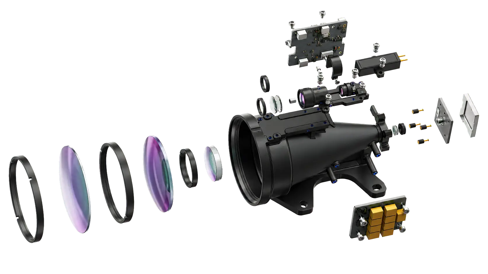
Compact 1535 nm pulse generation for direct time-of-flight ranging.
Controlled divergence, return collection and aligned optical axes.
Echo detection, timing, filtering and calibrated distance calculation.
Defined datums and retained alignment for predictable integration.
Command handling, self-test, operating modes and output frames.
Host-triggered acquisition for controlled measurement sequences.
Repeated measurement with a selectable update frequency.
Returns multiple detected surfaces when supported by the scene.
Limits accepted returns to a defined working-distance interval.
Provides status information for startup and host diagnostics.
Application solutions
From 33 ± 1 g compact modules to ≥20 km large-target configurations, the series combines model-dependent ≤±1 m accuracy, low standby power and digital output with packages selected for the actual target and host platform.
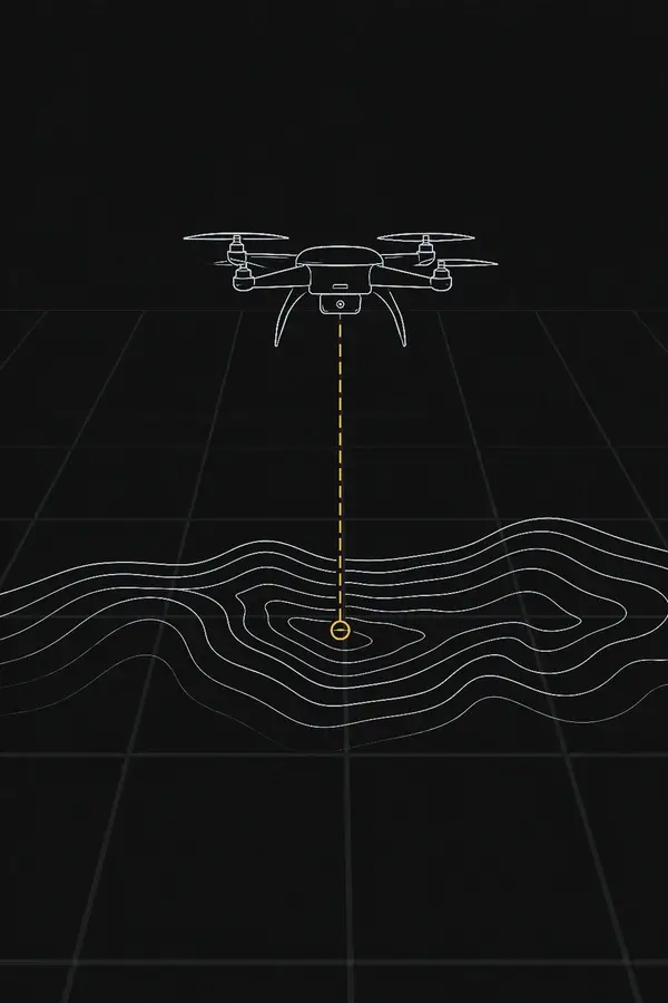
Low-mass distance input for terrain profiling, mapping and civil infrastructure inspection payloads.
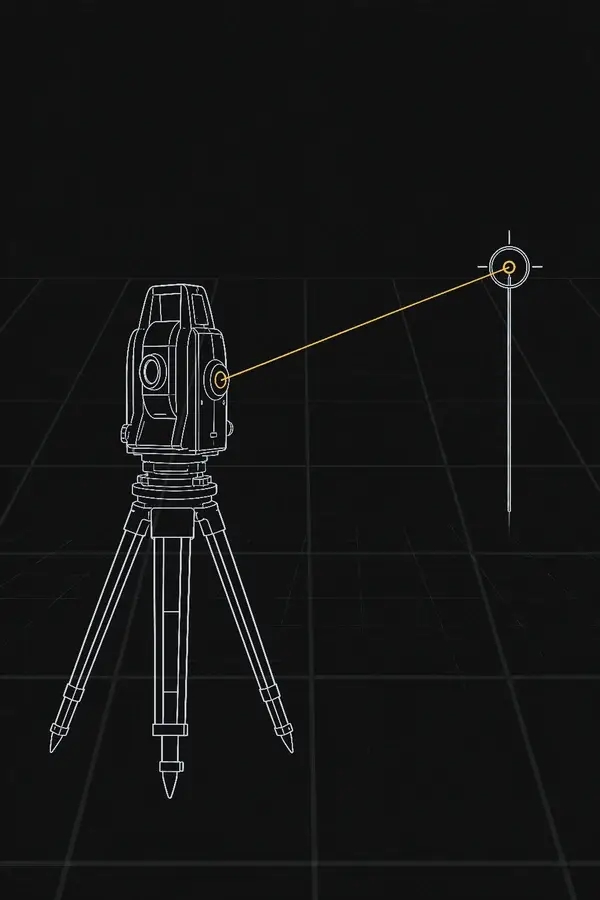
Repeatable digital range output for portable and fixed distance-measurement equipment.
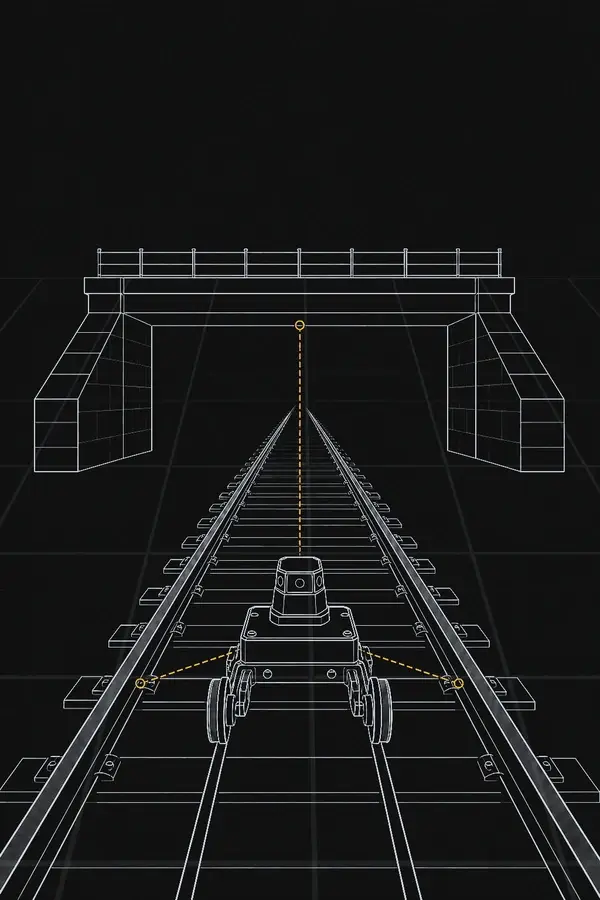
Distance, clearance and structural-position data for mobile and fixed inspection equipment.
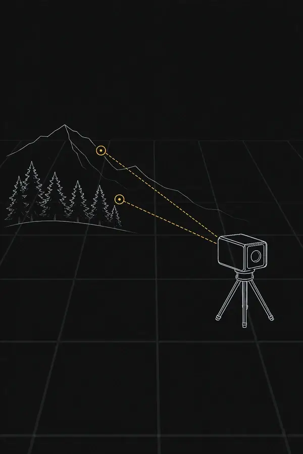
Range-gated measurements for remote sensing, monitoring and experimental instruments.
Low mass, low power, update rate, target footprint and required slant range.
Camera or sensor boresight, timestamping, vibration, host window and power transients.
Minimum range, distance accuracy, interface, target type and enclosure volume.
Optical-window transmission, mounting datum, cable routing and representative target validation.
Large-structure range, alignment stability, temperature range and mechanical robustness.
Incidence angle, surface material, platform motion, vibration and retained boresight.
Range gate, multi-return output, timing consistency and measurement frequency.
The host must provide scanning or pointing, pose data and point-cloud processing where required.
Protocol access, repeatability, target response and configurable operating modes.
Bench evaluation with the final power supply, window, mount and data-acquisition chain.
Laser rangefinder knowledge
A single optical pulse travels to the target and returns to the receiver. The module measures the round-trip time, validates the echo and calculates the line-of-sight distance.
Single-pulse TOF sequence
Distance accuracy is not determined by the formula alone. Timing resolution, detector bandwidth, echo signal-to-noise ratio, target depth, threshold logic and calibration all influence the reported result.
The Er:Glass source and transmitting optics launch a short 1535 nm pulse.
The receiving aperture collects a small portion of the energy reflected by the target.
The detector and timing circuit identify valid echoes and measure round-trip delay.
Signal processing applies gating and return logic before outputting distance and status data.
Beam divergence and target footprint
Divergence defines how quickly the illuminated footprint grows with distance. It must be considered together with pointing error, optical-axis stability and the receiver field of view.
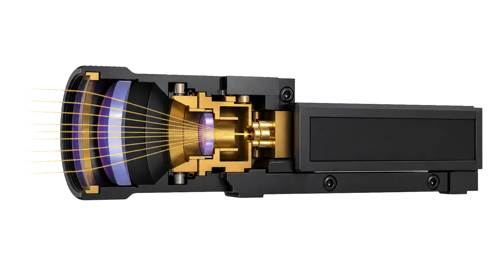 Transmitting optics
Er:Glass laser source
Transmitting optics
Er:Glass laser sourceModel-dependent optical configuration
The smallest configuration is specified at ≤0.6 mrad, while most longer-range configurations list ≤0.3 mrad. A smaller divergence improves target fill for compact targets, but demands tighter pointing and boresight control.
| Range | At 0.3 mrad | Engineering meaning |
|---|---|---|
| 1 km | ≈0.3 m | Compact footprint; alignment remains important. |
| 3 km | ≈0.9 m | Comparable to many small civil targets. |
| 5 km | ≈1.5 m | Target fill becomes a major link-budget term. |
| 10 km | ≈3.0 m | Small targets intercept only part of the pulse. |
What determines maximum range
Laser energy alone does not determine performance. The useful echo must survive beam spreading, atmosphere, target reflection, collection loss, background light and the receiver’s detection threshold.
Higher peak power can improve return strength, but energy, pulse width, repetition rate, Class 1 limits, power demand and thermal behaviour must remain balanced.
A narrow beam increases energy density on a compact target only when pointing error, vibration and boresight drift remain controlled.
Haze, rain, snow and airborne particles attenuate and scatter the pulse on both the outward and return paths. Lower visibility reduces range margin.
Collection area scales with D². A larger aperture gathers more return energy, while increasing package size, mass and host-window requirements.
The returned energy changes with illuminated area, wavelength-specific reflectivity, surface texture, moisture and incidence angle.
Window transmission, stray reflections, detector noise, background light, timing resolution, gain and gating all affect whether an echo is accepted.
Target size and reflectivity
A quoted kilometre value is meaningful only when target dimensions, reflectivity and atmospheric conditions are known.
Only part of the pulse reaches the target. A smaller target, lower reflectivity or steeper incidence angle reduces the returned signal and therefore the available range margin.
Most of the pulse can be intercepted, so large structures may be measured farther than the 2.3 × 2.3 m reference target. At very short range, highly reflective surfaces can also create excessive or stray returns.
Host optical window design
Window material, coating, thickness, spacing and parallelism affect transmission, internal reflections and transmit-to-receive isolation. Validate the assembled host, not only the bare module.
1535 nm integration starting points
Use these values as initial mechanical guidance, then confirm them against the selected module drawing and the production window.
Command timing and host software
Typical F-series timing provides an integration starting point. Confirm the exact timing, baud rate, electrical levels and output frame in the protocol supplied with the selected model.
Typical preparation before emission, followed by approximately 4 ms for echo processing and result output.
Typical preparation while the ranging state is active, followed by processing and host reporting.
Distance results are reported at the configured measurement frequency. Host timing and buffering should follow the model protocol.
Mechanical and electrical integration
These are non-hermetic OEM modules. Use the model-specific drawing and protocol as the design baseline, and design the host enclosure to control dust, condensation and relative humidity at or below 80%.
Confirm the module envelope, mounting-hole depth, optical-axis position, connector location and service access before releasing the host enclosure.
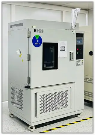
Testing, quality control and delivery
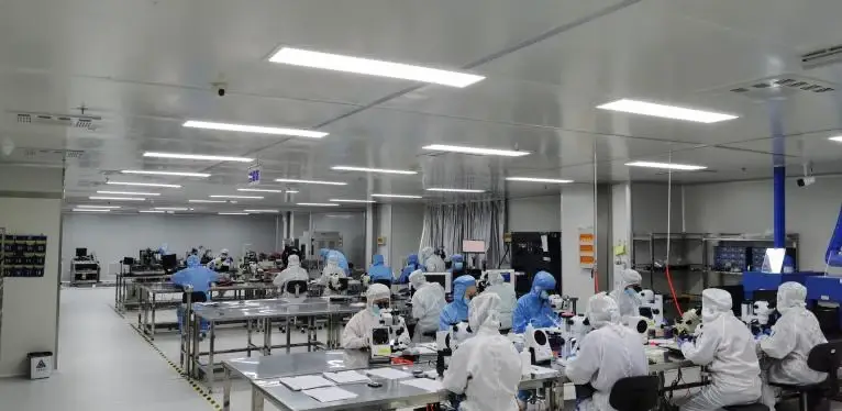
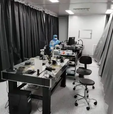
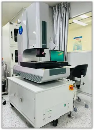
Laser output, optical-axis consistency, ranging accuracy, electrical behaviour and environmental performance are verified through defined production and release checks.
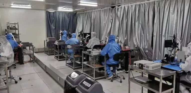
Dedicated workstations support Er:Glass source integration, transmit/receive alignment, circuit verification and calibrated ranging tests.
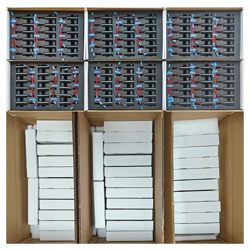
Individual protection keeps modules separated, secures cable tails and protects optical windows and connectors through handling and export transport.
Wavelength, pulse output, repetition frequency and output stability are checked against the model specification.
Transmit axis, receive field and mechanical reference are aligned and verified.
Distance output, valid-reading behaviour and target response are checked under defined test conditions.
Supply input, power demand, communication frames, self-test and operating modes are verified.
Specified operation is −40 to +60°C, with the 0300 model specified to +70°C.
Model data includes a 75 g @ 6 ms shock condition; vibration profiles are agreed for the intended host environment.
Each released module receives final electrical, communication, ranging and visual checks before packing.
Individual ESD-safe protection, separated shock-absorbing foam and moisture-control materials protect the module during storage and transport.
Optical windows and electrical connectors are protected separately; cable tails are restrained to prevent load transfer during handling.
Shipment can include model and serial-number labels, packing list and outgoing inspection record. Reinforced export packaging is available by shipment configuration.
Downloads and OEM / ODM support
Model-specific files keep dimensions, interfaces and operating limits tied to the quoted configuration. We also support host enclosure review, protocol integration and application-specific validation planning.
Request engineering filesOptical, electrical, mechanical and environmental specification.
Envelope, mounting features, optical axes and connector location.
Mechanical reference for enclosure and assembly-layout review.
Commands, output frames, status information and operating control.
Evaluation units, bench-test guidance, host software and integration support can be defined before design-in.
Interface, connector, cable, mounting envelope, protocol and validation-plan review for OEM / ODM projects.
Pre-sales FAQ
These questions define the optical, electrical and mechanical configuration required for quotation, sample evaluation and design-in.
The model class follows the specified distance for a 2.3 × 2.3 m target. A larger target can provide a longer specified distance, which is why both target conditions appear in the comparison table.
Provide the target dimensions and material, expected reflectance where known, minimum and maximum distance, visibility, target or platform motion, available installation volume and mass, supply rail, communication interface, operating temperature and the planned host-window construction. These inputs are more reliable than selecting by maximum range alone.
Start with installation volume, weight limit, target and required distance. Models in the 3 km to 8 km classes provide the smallest envelopes, beginning at 48 × 21 × 31 mm and 33 ± 1 g. Receive aperture, minimum range, peak power demand and interface must still be confirmed before selection.
Class 1 eye-safe classification applies to the module in its defined model configuration. The completed host instrument must be assessed after its final window, enclosure, power control, firmware and operating modes are fixed. Applicable IEC 60825-1 requirements should be reviewed during system release.
No. Range changes with target dimensions, reflectance, incidence angle, atmosphere, background light, optical-window transmission and alignment. The model table uses stated target conditions so alternatives can be compared consistently; representative-target testing is recommended for the final installation.
Divergence determines how quickly the illuminated spot grows with distance. At 0.3 mrad, the added spot diameter is approximately 0.3 m at 1 km, 1.5 m at 5 km and 3 m at 10 km. If the target is smaller than the spot, only part of the transmitted energy is returned. Confirm whether a model's value is specified as full angle and include the initial beam diameter in detailed calculations.
Use flat, parallel optical glass with an anti-reflection coating for 1525–1545 nm and keep it close to the module. A practical design starting point is 2–4 mm glass thickness, an air gap of no more than 4 mm, at least 1.5 mm clear-aperture margin beyond the projected transmit and receive lenses, and at least 2 mm additional structural margin. Final dimensions must be checked against the selected model, installation angle and enclosure tolerances.
The series supports model-dependent DC 5–28 V input with TTL or RS422 communication. Power design must account for the model's peak current during laser emission, not only standby consumption of ≤0.2 W. Use the model-specific pin definition, voltage levels and grounding requirements before connecting a host controller.
Single-shot and continuous measurement are supported with an adjustable 1–10 Hz rate. The series can report up to three targets and supports range gating plus front or rear return handling. Exact commands, output frames and availability are defined in the selected model's communication protocol.
For typical F-series operation, allow approximately 800 ms for the first command after power-up plus about 4 ms processing time, and approximately 250 ms plus 4 ms for subsequent commands. Continuous output can be set from 1 to 10 Hz. Confirm timing, baud rate and host timeout against the protocol supplied with the quoted model.
No. These are non-hermetic OEM modules. The host enclosure must control dust, condensation and relative humidity at or below 80%, while keeping the transmit and receive apertures clear.
Baud-rate options depend on the model and protocol. Pulse energy and divergence are optical safety and calibration parameters and are not assumed to be field-adjustable; any factory change requires an engineering review of range performance, power, thermal behaviour and the defined Class 1 configuration.
Model-dependent evaluation units, test guidance, datasheets, 2D drawings, 3D STEP files, connector definitions and communication protocols are available for design review. Connector, cable, mounting envelope, interface and command integration can be evaluated against the project requirements and validation plan.
Compliance and test documents are supplied only when they are applicable to, and verified for, the quoted configuration. Share the destination market and required document list during quotation so availability can be confirmed. The completed host product remains subject to its own laser-safety and product-compliance assessment.
We will recommend a model, identify the main integration risks and prepare the relevant engineering document package.