
Infrastructure inspection
Infrastructure Inspection Lasers: Build Around the Asset Decision
Lumexis develops 1535 nm laser rangefinder modules and 1.5 µm pulsed laser sources for civil railway, bridge, tunnel, and infrastructure measurement equipment.
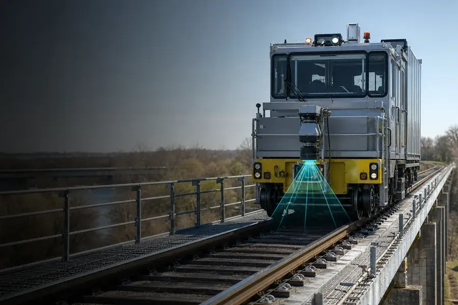
Lumexis develops 1535 nm laser rangefinder modules and 1.5 µm pulsed laser sources for civil infrastructure measurement equipment. The two product types solve different parts of the problem: a rangefinder module returns a distance along a defined line of sight, while a pulsed source can be integrated into a scanning LiDAR that builds many range samples into a point cloud.
Use a compact rangefinder module when the instrument needs an absolute distance, clearance check or camera-aligned range channel. Use a pulsed source when the OEM is building the transmitter inside a higher-rate scanner. In both cases, the finished result depends on optics, target geometry, platform pose, calibration and data processing.
Start with the measurement deliverable
| Application | Required output | Lumexis starting point | What the host system must add |
|---|---|---|---|
| Railway clearance and trackside asset measurement | Distance or 3D coordinates relative to a track reference | 1535 nm rangefinder module for selected lines of sight; pulsed source for dense scanning | scanner or pointing mechanism, encoder, position/attitude data, calibration and clearance model |
| Bridge geometry and condition documentation | Registered point cloud, dimensions or change map | 1.5 µm pulsed source for scanning; rangefinder for selected standoff measurements | scanning optics, imaging, survey control, registration and engineering interpretation |
| Tunnel profile and convergence monitoring | Cross-sections, over/underbreak or repeat-survey displacement | Pulsed source for profile scanning or rangefinder for fixed reference points | stable control network, scanner, temperature compensation and epoch-to-epoch registration |
| Corridor and right-of-way mapping | Georeferenced asset positions and clearance envelope | Pulsed source for mobile LiDAR | GNSS/IMU, timing, boresight calibration, cameras and feature extraction |
| Construction alignment and machine positioning | Repeated absolute distance to a defined surface or reference | Compact 1535 nm rangefinder module | aiming, target selection, controller interface and application-specific acceptance logic |
Fast match: if your drawing needs one distance channel, start with the rangefinder-module family. If your deliverable is a dense 2D profile or 3D point cloud, start with the pulsed-source and scanning architecture. A rangefinder does not become a scanner through software alone; angular sampling must be created and measured by the host instrument.
What the laser measures—and what it does not
A direct Time-of-Flight channel measures the interval between an outgoing optical pulse and a detected return:
R = cΔt / 2
The result is a range along the optical line of sight. To convert that range into a coordinate, the instrument also needs the origin and direction of the measurement. On a stationary scanner, those come from scanner angles and survey control. On a moving rail vehicle or road platform, they also require synchronized position, attitude and lever-arm calibration.
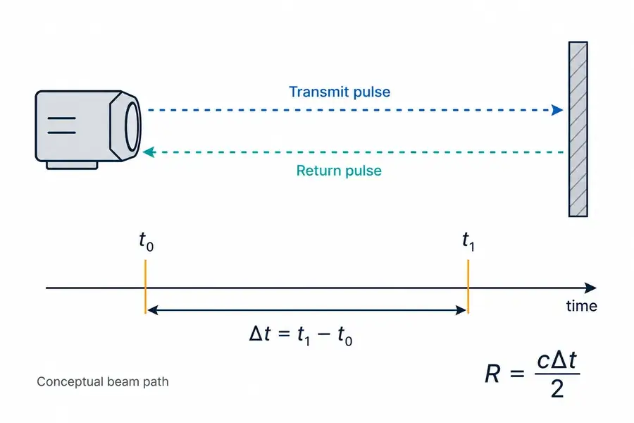
Measurement principle
Connect the optical measurement to system geometry
Direct Time-of-Flight principle used by an infrastructure range channel
Laser data can document geometry, clearance, movement and surface position. It does not independently determine the structural cause or severity of a defect. Bridge and tunnel decisions remain the responsibility of qualified inspection and engineering teams using the relevant standards and complementary methods.
Product route 1: 1535 nm rangefinder modules
The rangefinder module combines the pulsed transmitter, transmit optics, receiver, detector, timing and communication needed to return distance data. It is suitable when the OEM wants a compact ranging channel rather than developing a complete optical receiver and timing chain.
Practical infrastructure uses
- camera-aligned distance to a pier, deck edge, tunnel wall or trackside asset;
- vehicle-mounted standoff measurement to large civil surfaces;
- approach or positioning feedback for an inspection mechanism;
- multiple fixed lines of sight used to monitor selected geometric references;
- distance data combined with a pan/tilt or scanning unit supplied by the OEM.
Range classes for initial discussion
| Module | Published reference-target range class | Receive aperture | Minimum range | Typical infrastructure position |
|---|---|---|---|---|
| 1535-LXCJ0300 | ≥3.2 km | Φ16 mm | ≤15 m | Compact mobile or fixed measurement channel |
| 1535-LXCJ0500 | ≥5 km | Φ16 mm | ≤15 m | Longer corridors with a compact aperture |
| 1535-LXCJ0600 | ≥6 km | Φ21 mm | ≤20 m | Increased collection area for more demanding targets |
| 1535-LXCJ0700 | ≥7 km | Φ25 mm | ≤30 m | Long-standoff civil measurement platforms |
| 1535-LXCJ0800 | ≥8 km | Φ25 mm | ≤30 m | Higher range margin with a mid-size aperture |
| 1535-LXCJ1000 | ≥10 km | Φ40 mm | ≤50 m | Large structures and long corridors where size permits |
| 1535-LXCJ1500 | ≥15 km | Φ52 mm | ≤70 m | Specialized long-range instruments with a larger optical package |
Published reference ranges are tied to a defined target and visibility condition in the source specification. They are not universal ranges for rail steel, dark ballast, concrete, wet surfaces, cables or oblique tunnel walls. Select the smallest range class that covers the real target and working envelope with testable margin.
System architecture
Review the complete optical and measurement chain
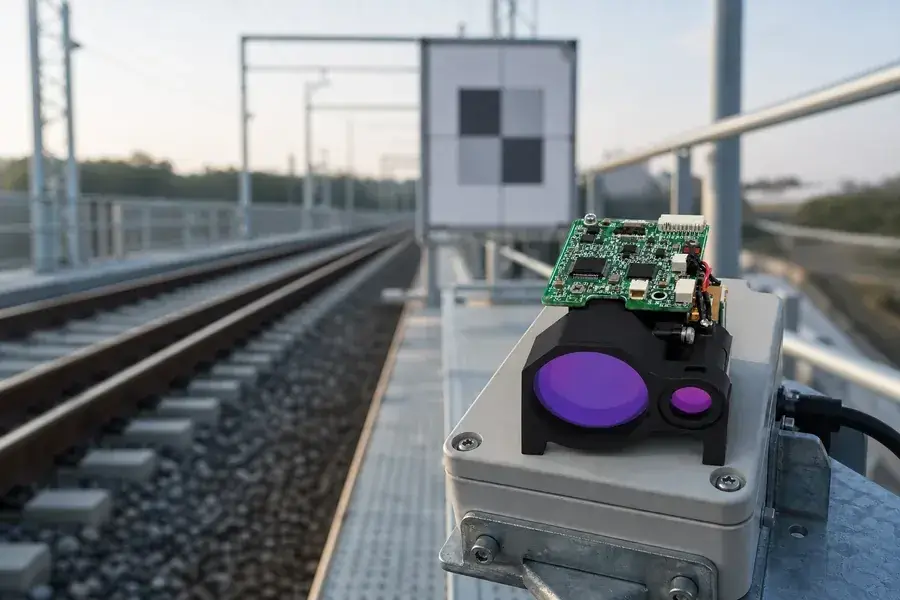
Compact rangefinder channel installed beside a railway corridor
Product route 2: 1.5 µm pulsed sources for scanning LiDAR
When an OEM controls the receiver, timing electronics and scanner, a 1.5 µm pulsed fiber laser can serve as the transmitter source. Higher pulse rate supports more measurement opportunities as the scanner sweeps across the scene. The useful point rate, however, is lower than or equal to the pulse rate because some returns will be rejected or missed.
This route is appropriate for:
- rail corridor point-cloud capture;
- bridge surface and geometry mapping;
- tunnel cross-section scanning;
- clearance-envelope analysis;
- repeated construction or deformation surveys;
- mobile mapping systems combining LiDAR with cameras and position/attitude sensors.
The source specification should include pulse energy, repetition rate, pulse width, wavelength, beam quality or source divergence, timing behavior, output interface and thermal conditions. The completed LiDAR must add transmit beam expansion, scanning, receive optics, detector, ranging electronics, time synchronization and calibration.
Railway inspection: separate geometry channels from condition channels
Automated rail inspection platforms often carry several sensor types because different defects require different physical measurements. Laser geometry or LiDAR can support rail profile, track alignment, clearance, asset location and point-cloud documentation. Cameras can support surface and component imaging. Other subsurface or internal conditions require other sensing methods.
Engineering visual
See how the source fits the complete instrument
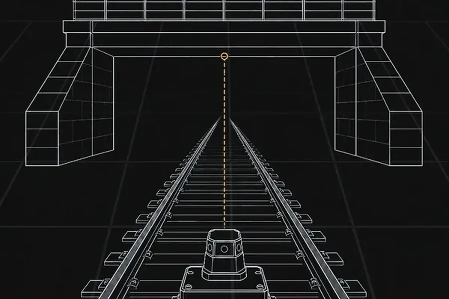
Conceptual rail corridor geometry with laser measurement points and a clearance structure
For a laser measurement channel, define:
- rail, sleeper, ballast, catenary or structure feature to be measured;
- coordinate frame and reference datum;
- vehicle speed and spatial sample interval;
- required cross-track and along-track coverage;
- expected target reflectance, angle and occlusion;
- vibration spectrum and mechanical mounting;
- GNSS-denied sections such as tunnels;
- calibration checks after installation or maintenance.
At speed (v) and accepted measurement rate (f), the idealized along-track sample spacing is:
Δx = v / f
This relationship is useful for early sizing, but it does not define point density by itself. Scanner pattern, scan angle, rejected returns, vehicle motion and overlap all affect the actual distribution.
Bridge inspection: use laser data as geometric evidence
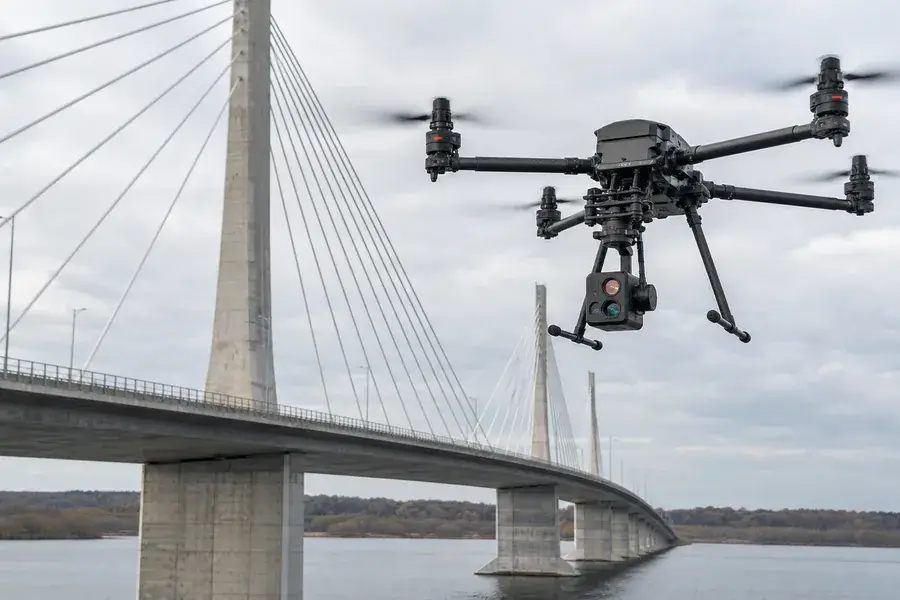
Bridge LiDAR can record accessible surfaces without placing an operator at every measurement point. It can support as-built documentation, clearance measurement, component location and repeat-survey comparison. Aerial or ground platforms may be selected according to access, scale and control requirements.
Engineering visual
See how the source fits the complete instrument
Aerial LiDAR platform collecting conceptual geometry from a civil bridge
Engineering teams should distinguish:
- range precision: repeatability of an individual range sample;
- point accuracy: coordinate accuracy after angle, pose and calibration errors;
- registration accuracy: agreement between scans or survey epochs;
- surface-model uncertainty: effect of point spacing, incidence angle and reconstruction;
- change-detection threshold: the smallest movement or loss that can be distinguished from combined uncertainty.
A scanner may report millimetre-scale range precision while the final registered point cloud has a larger coordinate uncertainty. Survey control, platform pose, boresight and time alignment must be included in the acceptance test.
Tunnel inspection: close range can be the hard requirement
Tunnel walls may be only a few metres from the sensor even when the source platform is capable of kilometre-scale ranging. Minimum range, receiver recovery and strong near returns can therefore matter more than headline maximum range.
For tunnel profiles and convergence monitoring:
- confirm the nearest wall and equipment distance at every scan angle;
- control occlusion from vehicles, cables and temporary works;
- use stable survey references for repeat measurements;
- account for dust, moisture, dark lining and wet reflective patches;
- record temperature and mechanical state when comparing survey epochs;
- validate registration and change thresholds with known references.
Fixed rangefinder channels can monitor selected points, while a scanner captures a cross-section or full surface. They answer different questions and may be combined in one monitoring design.
Parameters that decide whether the range channel works
Target size and beam footprint
For a far-field estimate, spot diameter grows approximately with range (R) and full-angle divergence (θ):
[ d≈ Rθ ]
If the spot overfills a narrow cable, rail edge or structural member, only part of the transmitted energy contributes to that target. The remainder can produce background or a second return. Beam divergence must be considered with pointing accuracy and the receiver field of view.
Surface reflectance and angle
Dry concrete, wet concrete, painted steel, rusted steel, ballast and vegetation return different signal levels. Oblique surfaces send less energy back toward a coaxial receiver than a surface facing the sensor. Test the real material at the worst expected angle.
Receive aperture and background
A larger receive aperture collects more return energy but increases package size and can admit more background depending on the field of view. Spectral filtering, receiver field of view and detection logic help control unwanted light and adjacent returns.
Pulse rate and scan speed
High pulse rate supports denser sampling, but average power, thermal load, receiver recovery and data processing must remain within limits. A production specification should state commanded pulse rate, emitted pulse rate, accepted range rate and delivered point rate separately.
Timing and platform synchronization
On a moving platform, even a small timing offset between the range event, scanner angle and position/attitude record creates coordinate error. Use a common time base or characterized synchronization path, and verify it dynamically rather than only on a stationary bench.
Window and contamination
The host window adds transmission loss, reflections and possible ghost returns. Dust, water and cleaning residue can change the result over time. Define window material, coatings, angle, aperture and a maintenance strategy before final range validation.
Accuracy budget for a mapped point
A georeferenced target point can be summarized conceptually as:
psurface = psensor + Rulook
Errors can enter through sensor position, range, scanner angle, attitude, lever arm, boresight and time alignment. Because these terms interact, point-cloud accuracy cannot be inferred from the rangefinder’s distance accuracy alone.
For procurement, request separate acceptance values for:
- distance accuracy and repeatability on defined targets;
- angular accuracy or scanner calibration;
- boresight and lever-arm calibration;
- platform position and attitude performance;
- time synchronization;
- registered point-cloud accuracy in a representative operating scene.
Integration workflow
1. Define the asset and output
Provide the structure, material, range envelope, platform and final deliverable: one distance, cross-section, clearance report, point cloud or change map.
2. Build target-conditioned range cases
List the smallest and darkest required targets, worst incidence angles, nearest strong surface and expected weather or contamination. Use these cases instead of a single maximum-distance number.
3. Choose module or source architecture
Select a complete rangefinder module for a self-contained distance channel. Select a pulsed source if your team is building the scanner and receiver. Decide early because mechanical, electrical and software responsibilities differ substantially.
4. Close sampling and motion budgets
Relate vehicle speed, scan pattern and accepted measurement rate to required spatial coverage. Include vibration, motion distortion and GNSS-denied operation.
5. Calibrate the complete instrument
Calibrate range offset, angular axes, boresight, lever arm and timing. Use known targets and representative platform motion. Document checks after service or sensor replacement.
6. Validate the decision output
Test clearance, dimensional or change-detection results—not only raw range. Include representative concrete, steel, ballast, vegetation, wet surfaces and partial occlusion where relevant.
Information to send Lumexis
- infrastructure type and measurement deliverable;
- stationary, vehicle, rail or aerial platform;
- minimum, normal and maximum distance;
- target dimensions, materials and incidence angles;
- single-point rate or desired point density;
- scanner and receiver architecture, if already selected;
- aperture, package, mass and power limits;
- communication, trigger and timing interfaces;
- temperature, vibration, window and contamination conditions;
- prototype schedule, expected annual quantity and validation plan.
Frequently asked questions
Can a laser rangefinder module create a 3D model of a bridge?
Not by itself. It returns distance along one line of sight. A 3D model also needs controlled angular sampling or platform motion, position and attitude data, calibration, registration and point-cloud processing.
Which product is better for railway clearance measurement?
A rangefinder module fits selected clearance lines or camera-aligned distance checks. A high-rate pulsed source integrated into a scanner fits dense clearance-envelope mapping. The required output determines the product route.
Does maximum range matter in a tunnel?
Often minimum range, strong-return recovery and scan geometry are more important. The nearest wall or equipment may sit inside the near limit of a long-range module, so the complete angular envelope must be checked.
Can LiDAR identify structural damage automatically?
It can supply geometry and change evidence to an analysis system. Automated classification requires validated algorithms and appropriate ground truth, while structural conclusions require qualified engineering interpretation and may need complementary inspection methods.
Why can two surveys disagree even when the range sensor is stable?
Differences can come from control points, registration, platform pose, boresight, time synchronization, surface condition or sampling geometry. Evaluate the complete point uncertainty and survey workflow.
What should procurement compare between suppliers?
Compare target-conditioned range, minimum range, accuracy and repeatability, accepted measurement rate, aperture, divergence, interface, package, environmental limits, calibration support and the exact acceptance test. A single headline range is not enough.
Build the range channel around the asset decision
Send the structure, platform, target cases and required output. Lumexis will help determine whether a 1535 nm rangefinder module or a 1.5 µm pulsed source is the right starting point, then align the optical, timing and mechanical interface with your inspection instrument.
Lumexis — precision laser sources, engineered for the real world.
Technical references
- Federal Railroad Administration: Automated Track Inspection Program
- Federal Railroad Administration: LiDAR Grade Crossing Data Collection
- Federal Railroad Administration: Laser Triangulation for Track Change and Defect Detection
- Federal Highway Administration: Advanced Technologies in Bridge Inspection
- RIEGL: Rail Mobile Laser Scanning Applications
- Trimble: Tunnel Scanning, Surveying and Monitoring Workflows