
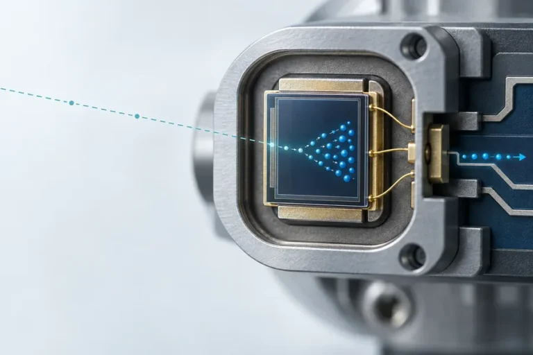








An RS422 laser rangefinder module can be a practical choice when the ranging head and host controller cannot share a short, quiet connection. Differential signaling helps the receiver respond to the voltage difference between paired conductors rather than to either conductor alone. The result is a more resilient communications layer when cable routing, enclosure layout, and installation discipline are handled properly.
Lumexis supports OEM integration of laser rangefinder modules for industrial, civil, and research instruments. Here is how to evaluate RS422 at the system level.
RS422 laser rangefinder module: why differential signaling matters
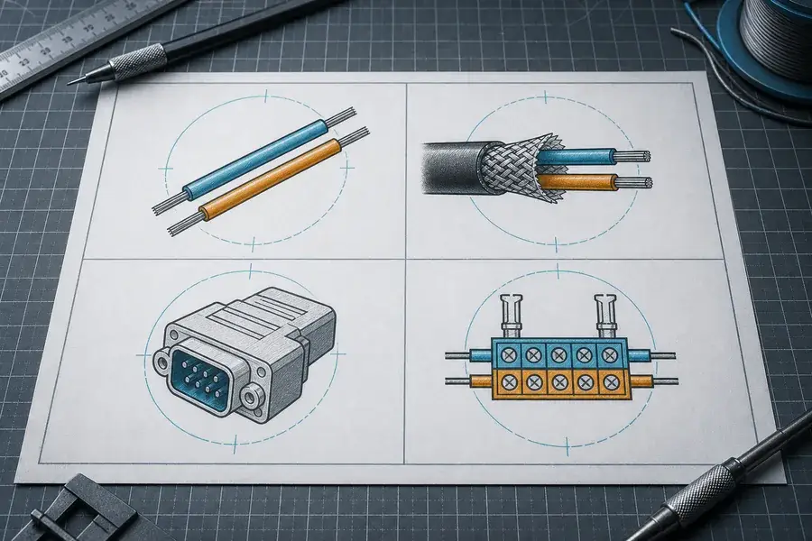
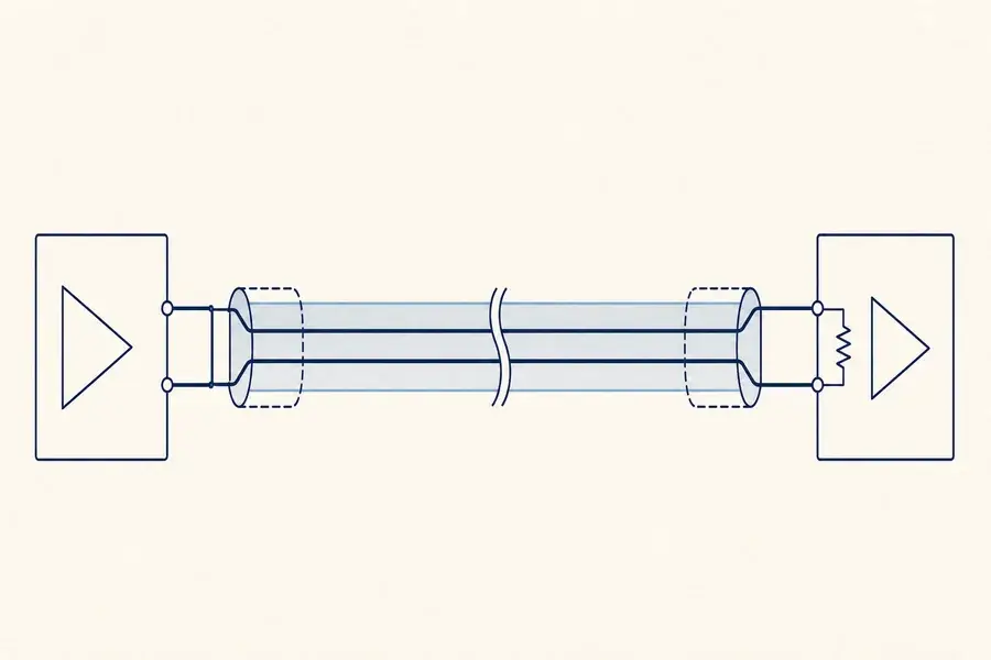
UART-style single-ended serial links are efficient for nearby electronics. As cable length and electrical complexity increase, the signal path, return path, and reference difference between enclosures become more important. RS422 uses paired conductors and a differential receiver, which can improve noise tolerance when the system is correctly wired.
That does not make every long cable interchangeable. Cable impedance, pair twisting, shield treatment, connector quality, route separation, and termination determine whether a link stays clean. The interface standard is a starting point; the installed assembly is the product.
Plan the cable as a transmission path
For a point-to-point RS422 connection, use the cable and transceiver documentation to establish the pair assignment and termination approach. Long or fast-transition links can reflect energy at impedance changes. Termination near the receiving end is commonly used for RS422 point-to-point topology, but the correct implementation must match the particular module and system design.
Build the harness documentation around these controls:
| Design choice | Engineering question |
|---|---|
| Twisted pairs | Are each differential signal’s two conductors kept together? |
| Shield | Where is it bonded, and how is the enclosure boundary handled? |
| Ground reference | Is there a defined reference path without creating an unintended loop? |
| Termination | Is the value and location consistent with cable and interface guidance? |
| Stubs | Have branch lengths been minimized? |
| Routing | Is the cable separated from high-current or switching paths where possible? |
Separate communications validation from ranging validation
When a distant sensor head returns implausible data, it is tempting to investigate optics first. Start by determining whether the serial transport is sound. Capture the differential signal at the installed connector, compare it against a known-good short harness, and record frame integrity at representative operating conditions.
Then test ranging on controlled targets with the same physical installation. This sequence prevents a cable reflection, connector fault, or grounding issue from being misclassified as an optical issue. Our laser rangefinder module datasheet guide explains how to turn the module’s interface and environmental data into a test plan.
Common integration mistakes
The most common failures are not exotic: reversed polarity, a differential pair split across a connector, a termination added by habit rather than by design, a long branch, or a shield scheme that changes between prototype and production. Another recurring issue is treating the communication result as the only diagnostic. A valid frame confirms transport, not that the resulting measurement is suitable for the application.
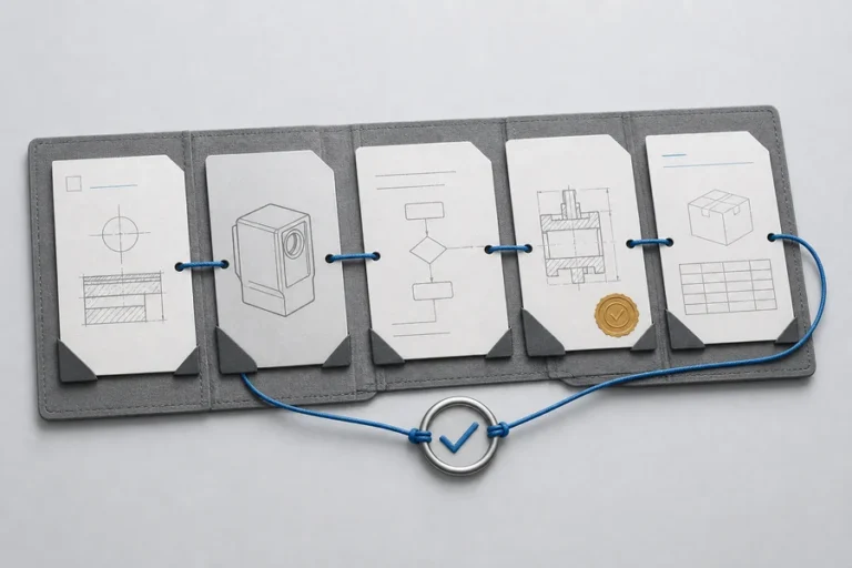
Use version-controlled wiring drawings and a cable continuity test. Include an installation-level communication test in production verification, especially if the final equipment uses multiple enclosure sections or serviceable harnesses.
Design for service as well as first installation
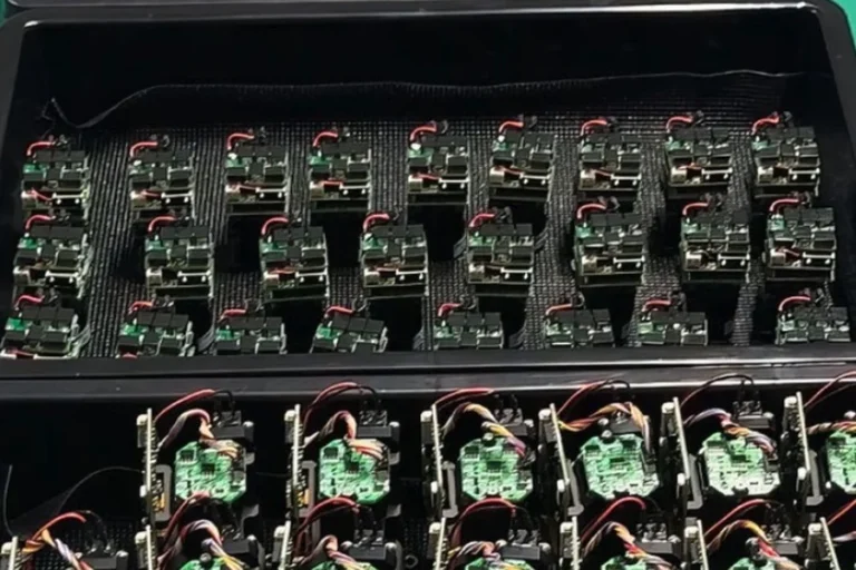
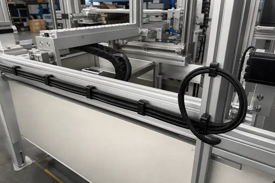
An interface that works on the first build can fail after a replacement harness, connector rework, or revised routing path. Define what a service technician may disconnect, how the connector is keyed, and what communication check proves the repaired unit is healthy. Capture the installed-cable configuration in the production record.
When to specify RS422
Specify an RS422 laser rangefinder module when the physical architecture calls for a point-to-point differential connection and the interface is supported by the selected module configuration. It is not automatically the best answer for every long run; a shared network, host architecture, update rate, and service model may point to another interface.
For a selection framework, read how to choose a laser rangefinder module. Lumexis engineers can review the module location, cable path, host controller, and acceptance criteria with your OEM team. Contact us to start that conversation.
Technical reading: Analog Devices AN-960 explains differential transmission and why termination and line geometry matter for RS422 links.
FAQ
Is RS422 the same as UART?
They address different layers. UART describes asynchronous byte framing, while RS422 describes a differential electrical signaling approach. A system can use UART-format data through an RS422 transceiver, but the connector and protocol still need to be defined for the specific implementation.
Does every RS422 cable need the same termination?
No. Termination depends on the topology, cable characteristics, transceiver, data rate, and installed geometry. Apply the module and transceiver guidance rather than copying a resistor value from another product.
Can a shield replace correct differential-pair routing?
No. Shielding and pair integrity solve different problems. Keep the two conductors of each differential signal together, then implement shielding and grounding as a deliberate enclosure-level design.
How should we test a long installed link?
Test with the final cable, connectors, power system, and processor load. Check startup, valid-frame rate, timeout recovery, and communications while the equipment performs its normal electrical functions. Repeat the range test after the transport layer is verified.