


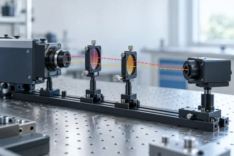
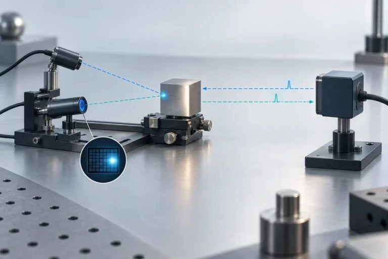



A laser rangefinder can return accurate distance data and still fail at the system boundary. One undocumented byte order, timeout, status code, or startup message is enough to turn a clean bench demo into intermittent field behavior.
A laser rangefinder protocol is the byte-level contract between the module and its host. It defines commands, responses, frame boundaries, payload encoding, integrity checks, timing, status meanings, and version behavior. Reliable integration comes from implementing that exact contract, rejecting malformed or stale data, and testing recovery as carefully as normal measurements.
Start the laser rangefinder protocol at the right layer
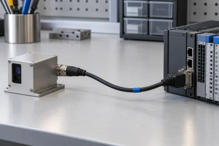
The connector and the message are different design layers. UART describes asynchronous serial signaling. RS-232 and RS-422 add electrical characteristics for the installed link. A supplier-specific command set or Modbus RTU then defines how bytes become requests, measurements, settings, and faults.
Do not infer one layer from another. Two modules may both expose UART while using different baud rates, frame headers, checksums, command codes, byte order, and response timing. The same application protocol may also be carried over more than one electrical interface.
Use our laser rangefinder interface comparison to choose the physical link first. If the host connects at logic level, the UART integration guide covers voltage, grounding, and receive/transmit direction. The released protocol document for the exact module and firmware must then control the software implementation.
Map every field before writing the parser
Binary frames commonly contain some combination of a synchronization field, address or version, command or message type, length, payload, status, sequence information, and an integrity field. That is a useful review model, not a universal frame format.
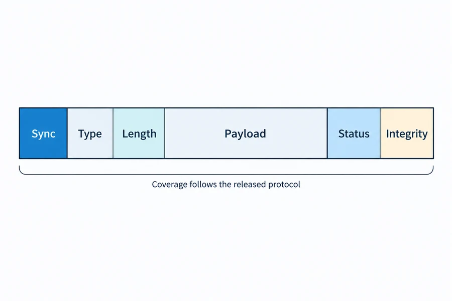
For every released message, document these questions:
- Which bytes identify the start of a frame, and can those values appear inside the payload?
- Does the length include the header, payload, checksum, or only selected fields?
- Is a multi-byte value transmitted least-significant byte first or most-significant byte first?
- What are the scale, offset, units, signedness, and reserved values?
- Which bytes are covered by the checksum or CRC, and in what transmitted order?
TI’s UART examples use different combinations of start, address, control, length, payload, delimiters, and integrity fields. Neither layout belongs in a rangefinder driver unless it matches the supplier’s released interface control document.
Create a field table and at least one known-good hexadecimal request and response for each command. A prose description without byte positions is not enough for independent implementation or regression testing.
Separate commands, acknowledgments, measurements, and faults
A robust host should not treat every valid frame as a distance. Use explicit message classes or command-response rules so the parser can distinguish configuration acknowledgment, measurement data, device status, startup notification, and error reporting.
Define whether the protocol is request-response, periodic streaming, event-driven, or a mixture. For a request-response exchange, state whether one request produces one reply, what identifies the matching reply, and what the host does with an unrelated frame. For streaming output, define when the stream begins, its nominal update behavior, and how the host regains synchronization after attaching mid-frame.
Status belongs beside the value, not in an afterthought. The host needs a documented way to distinguish a valid result from out-of-range, busy, no-return, internal fault, invalid command, or communication error. If the module has no explicit freshness counter, the host should still assign reception time and enforce a maximum acceptable data age.
Treat startup and restart as protocol states. A device may emit identification data, restore saved configuration, or remain busy before accepting a command. The RS-232 rangefinder integration guide explains why a working cable does not prove correct application behavior.
Implement parsing as a state machine, not a fixed read
A serial read can return part of a frame, several frames, or bytes that begin in the middle of a message. Code that calls read(N) once and assumes a complete reply will eventually misalign.
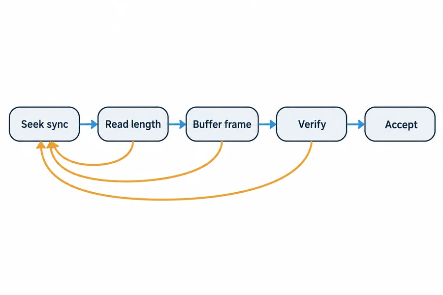
A safer parser keeps persistent receive state:
- Search for the documented synchronization pattern.
- Read enough fixed fields to determine the message type and expected length.
- Reject impossible lengths before allocating or waiting for more data.
- Buffer until the complete candidate frame arrives or a timeout expires.
- Verify the checksum or CRC over the exact documented byte range.
- Decode only a recognized message type with a valid payload length.
- On failure, discard the smallest safe amount and resume the header search.
Set bounds for payload length and buffer use. Reserved commands, impossible lengths, and partial frames should not hold the parser indefinitely. Count rejections and timeouts for diagnosis.
A checksum is only useful when its definition is exact
“Checksum” does not identify an algorithm. It might mean an additive sum, XOR, one’s complement, CRC-16, or another rule. Coverage, initial value, polynomial, reflection behavior, final XOR, and byte order can all change the result.
The Modbus Serial Line guide, for example, defines a specific CRC-16 procedure and transmits the low-order CRC byte before the high-order byte. That convention applies to Modbus RTU. It must not be transferred to a supplier-specific laser rangefinder protocol unless the supplier explicitly adopts it.
Keep the integrity routine small and test it separately. Store golden vectors with the full input bytes and expected result. Include one-bit corruption, missing-byte, and swapped-byte cases. If requests and responses use different coverage rules, give them separate functions and tests.
An integrity check detects some transmission or framing errors. It does not prove that the distance is current, plausible, associated with the requested mode, or safe for the host to use.
Define timeouts, retries, and stale-data behavior together
Protocol timing must include more than baud rate. Record command processing time, measurement latency, response timeout, inter-command spacing, streaming cadence, restart delay, and the maximum age accepted by the consuming function.
Avoid an automatic retry loop with no state model. A repeated measurement command may be harmless, may restart acquisition, or may create duplicate replies depending on the module. Configuration writes need even more care because retrying after an uncertain acknowledgment can produce an unknown host-device state.
Use bounded retries only where the command is documented as safe to repeat. After the limit is reached, expose a clear communication fault and move the system to its approved fallback. Never preserve the last valid distance indefinitely. Mark it stale when its age exceeds the system requirement, even if no corrupt frame was received.
Control protocol versions like a hardware interface
The protocol document should identify compatible hardware and firmware revisions. Every reserved byte and bit needs a stated transmit and receive rule.
Request these supplier deliverables before design release:
- versioned interface control document and change history;
- command, response, status, and error tables;
- field definitions with units, scale, byte order, and valid ranges;
- checksum or CRC definition plus golden vectors;
- startup, reset, timeout, retry, and configuration-persistence behavior;
- a known-good host example and a method to read firmware identity.
Freeze the document revision with the approved module and host firmware. If a new module firmware changes parsing, timing, or status meaning, treat it as an interface change that requires review and regression testing.
Validate the failure paths before production
Begin with captured known-good exchanges. Confirm every command, response, byte order, unit conversion, and status value against the released document. Then inject faults deliberately rather than waiting for noise to create them.
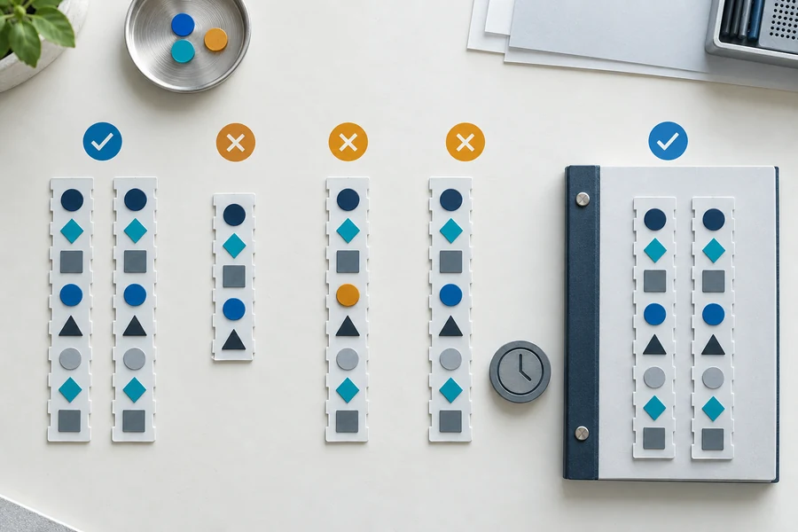
Test a truncated frame, bad integrity field, unknown command, invalid length, delayed reply, duplicate reply, extra leading bytes, back-to-back frames, mid-frame connection, module restart, and host restart. Confirm that valid traffic after each fault is decoded correctly. Test buffer overflow protection and log-rate limits as well as the happy path.
Move from a desktop adapter to the final host, harness, power architecture, firmware scheduler, and expected traffic. Our laser rangefinder range-test guide shows how controlled conditions and acceptance rules turn demonstrations into evidence.
What Lumexis reviews with OEM teams
Lumexis applications engineers can review the electrical interface, protocol contract, host parser behavior, validation plan, and fault handling with your team. That work fits inside a wider laser rangefinder module integration process covering optical, mechanical, thermal, power, and data boundaries.
Our Wuxi office works with the 14,000-square-meter Taizhou manufacturing base. Electronics, firmware, weak-signal algorithms, test-method development, assembly, burn-in, and final testing support OEM qualification. Browse the laser rangefinder module family or review our engineering services when a standard interface does not fit.
FAQ
Is a UART interface the same as a laser rangefinder protocol?
No. UART defines asynchronous serial transmission at the hardware-peripheral level. The laser rangefinder protocol defines frame boundaries, commands, responses, payload meanings, status values, timing, and integrity checks carried over that link. Voltage level and physical wiring are separate decisions again.
Should a host use a checksum or a CRC?
Use the algorithm defined by the released module protocol. Do not replace an additive checksum with a CRC or assume that every CRC-16 uses the same parameters. If you control both ends of a new design, choose an integrity method from the system risk and test it with published golden vectors.
How should software recover after receiving a bad frame?
Reject the candidate frame, record the error, and return to a bounded synchronization search. The exact discard rule depends on the protocol’s delimiter and escaping method. A parser should recover when the next valid frame arrives without requiring a power cycle or accepting bytes from the corrupt frame as a measurement.
What protocol files should an OEM request from a supplier?
Request a versioned interface control document, command and status tables, field-level byte definitions, integrity algorithm, timing rules, startup and reset behavior, firmware compatibility, golden request-response vectors, and a known-good host example. Keep them under the same configuration control as the module and host firmware.
How do you test stale range data?
Stop or delay valid measurement frames while leaving the host running. Verify that the consumer marks the distance unavailable at the specified age limit, records the communication state, and follows the approved fallback. Then restore valid traffic and confirm recovery without replaying the old value.
References
- TI MSPM0 Communication Modules: UART User Guide
- TI SmartRF Packet Sniffer 2: Command Interface
- Modbus Serial Line Protocol and Implementation Guide V1.02
Share your target module, host interface, firmware revision, update rate, timeout budget, and fault-response requirement through the Lumexis contact page. We can confirm a standard-product fit and three-day shipment when stock is available, or review the protocol and lead time for a custom or private-label project.