
Laser ranging solutions
Laser Ranging: Match the Channel to the Target First
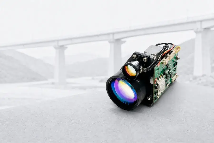
Lumexis develops and manufactures compact 1535 nm laser rangefinder modules for civil remote sensing, surveying, railway and infrastructure inspection, large-scale machine vision, industrial measurement, and scientific instruments. Our single-pulse Time-of-Flight platforms cover 3 km to 15 km reference-target range classes, with defined options for receive aperture, beam divergence, package size, mass, power, and host communication.
The fastest route to a workable solution is to define six inputs:
- target size, material, reflectivity, and angle;
- normal and maximum working distance;
- visibility, weather, and optical-window conditions;
- allowable size, weight, and receive aperture;
- measurement rate, latency, and target-selection logic;
- supply, interface, cable length, and environmental limits.
Start with the application
A laser rangefinder module measures a distance channel. It does not create a 3D point cloud by itself. In a complete instrument, range data can be combined with a scanning mechanism, camera, encoder, GNSS receiver, IMU, or machine controller to calculate height, position, clearance, coordinates, or inspection geometry.
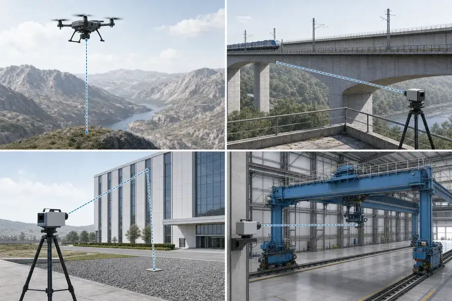
Application fit
Connect the range channel to the complete instrument
Use the target, working distance, mounting conditions, update rate, and host interface to define the measurement channel before selecting a module.
| Application | What the range channel contributes | Start the specification with | Parameters that usually decide the fit |
|---|---|---|---|
| Civil airborne remote sensing and altimetry | Standoff or altitude data that can be combined with platform position and attitude | Height envelope, ground or structure type, update rate, payload mass | target return, minimum range, measurement rate, mass, power, alignment |
| Railway and infrastructure inspection | Absolute distance to bridges, towers, trackside structures, slopes, or large civil assets | Structure material, incidence angle, stand-off distance, visibility | target fill, beam divergence, receive aperture, window contamination, vibration |
| Surveying and geospatial instruments | A single range value that can be combined with angle and position to calculate coordinates | target type, farthest working distance, coordinate workflow | accuracy, valid-measurement rate, alignment, RS422/TTL interface, calibration |
| Large-scale machine vision and industrial measurement | Absolute distance for positioning, approach monitoring, or geometric context across a large scene | object material, closest distance, control latency, required update rate | minimum range, reflectivity, bright-background rejection, interface, timing |
| Scientific and field instruments | An integrated transmitter, receiver, timing, and communication channel for experiments | trigger sequence, target, data logging, optical access, environmental range | command protocol, repeatability, raw operating conditions, calibration plan |
Where this platform is not the first choice
- For centimetre-scale displacement sensing or very short working distances, choose a short-range displacement sensor rather than a kilometre-class pulsed module.
- For dense 2D or 3D scene reconstruction, the host system must add angular scanning or imaging and point-cloud processing.
- For measurements through fog, rain, dust, steam, dirty windows, or strong specular reflections, validate the finished system under the real condition. A wavelength label does not remove propagation or target-return limits.
Match the target before the distance
A statement such as “5 km range” is incomplete without a target and test condition. The same module can produce different usable ranges for a large diffuse structure, a smaller object, a dark surface, a tilted surface, or a partially filled target.
Use this procurement sequence:
| Decision | Engineering question | Why it changes the result |
|---|---|---|
| Target geometry | How large is the projected target at the measurement angle? | If the beam spot overfills the target, only part of the pulse contributes to the useful return. |
| Surface response | What material, reflectivity, roughness, and incidence angle are expected? | A low-return or oblique surface may require more collection area or shorter working distance. |
| Atmosphere | What visibility, humidity, rain, fog, dust, or heat shimmer is realistic? | The pulse experiences loss on both the outbound and return paths. |
| Optical alignment | What boresight tolerance can the host hold over temperature and vibration? | A narrow beam improves target fill only when the transmit axis stays on the target and inside the receive field of view. |
| Detection logic | Is the desired return the first, strongest, last, or gated target? | Foreground objects and multiple surfaces can create more than one return. |
| Integration budget | What are the limits for aperture, mass, power, window, interface, and cable? | Range is a system outcome; improving one parameter usually consumes space, power, cost, or verification effort elsewhere. |
Lumexis 1535 nm module platform
The table below is a selection overview, not a replacement for the order-specific technical specification. The reference range is tied to a 2.3 × 2.3 m target with reflectivity of at least 0.3 under the visibility condition stated in the source specification. Actual performance changes with target fill, incidence angle, atmosphere, host window, alignment, detection threshold, and system configuration.
| Lumexis model | Reference-target range | Receive aperture | Beam divergence | Minimum range | Accuracy | Rate | Maximum dimensions | Mass | Default interface |
|---|---|---|---|---|---|---|---|---|---|
| 1535-LXCJ0300 | ≥3.2 km* | Φ16 mm | ≤0.6 mrad | ≤15 m | ≤±1 m | 1–10 Hz | 48 × 21 × 31 mm | 33 ± 1 g | RS422; TTL optional |
| 1535-LXCJ0500 | ≥5 km** | Φ16 mm | Confirm by configuration | ≤15 m | ≤±1 m | 1–10 Hz | 50 × 23 × 33.5 mm | ≤40 g | TTL; RS422 optional |
| 1535-LXCJ0600 | ≥6 km** | Φ21 mm | ≤0.3 mrad | ≤20 m | ≤±1 m | 1–10 Hz | 65 × 40 × 28 mm | ≤55 g | RS422 |
| 1535-LXCJ0700 | ≥7 km** | Φ25 mm | ≤0.3 mrad | ≤30 m | ≤±1 m | 1–10 Hz | 65 × 46 × 32 mm | ≤72 g | RS422 |
| 1535-LXCJ0800 | ≥8 km** | Φ25 mm | ≤0.3 mrad | ≤30 m | ≤±1 m | 1–10 Hz | 65 × 46 × 32 mm | ≤72 g | RS422 |
| 1535-LXCJ1000 | ≥10 km** | Φ40 mm | ≤0.3 mrad | ≤50 m | ≤±1.5 m | 1–10 Hz | 83 × 61 × 48 mm | ≤135 g | RS422 |
| 1535-LXCJ1500 | ≥15 km** | Φ52 mm | ≤0.3 mrad | ≤70 m | ≤±1.5 m | 1–10 Hz | 104 × 61 × 74 mm | ≤191 g | RS422 |
* Reference visibility ≥12 km in the source specification.
** Reference visibility ≥20 km in the source specification.
Practical platform logic
- Start with the smallest range class that covers the real working envelope with testable margin. Overspecifying maximum range can increase aperture, package, mass, power, and cost.
- Treat minimum range as a hard integration input. A long-range module may not be suitable for a scene that frequently places strong targets inside its near limit.
- Compare target-specific ranges, not only the largest number in a data sheet. A large structure and a smaller object are different optical cases.
- Confirm the final data sheet before mechanical release. Interface, connector, cable, mounting, window, and order-specific options must match the production configuration.
How pulsed Time-of-Flight laser ranging works
A direct Time-of-Flight rangefinder emits a short pulse, records the emission event, detects the returned energy, and measures the round-trip interval. The one-way distance is:
R = cΔt / 2
where:
- R is the one-way distance;
- c is the speed of light in the propagation medium;
- Δt is the measured time between the outgoing and returned events;
- the factor of two accounts for the trip to the target and back.
Working principle
From pulse timing to a usable distance value
A direct Time-of-Flight module coordinates the laser source, transmit and receive optics, detector, timing electronics, validity logic, and host communication as one ranging chain.
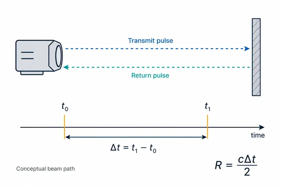
A complete module coordinates several functions:
- Control and drive trigger the source and manage single or continuous ranging.
- The erbium-glass source generates a short pulse around 1535 nm.
- Transmit optics set beam diameter, divergence, and axis.
- The target returns a small fraction of incident energy toward the sensor.
- Receive optics collect part of that return and reject out-of-field light.
- An InGaAs APD receiver chain converts the 1.5 μm return into an electrical event. Commercial InGaAs APDs are specifically available for 1550 nm LiDAR detection.4
- Timing and control electronics estimate the interval, apply validity logic, and send distance data to the host.
The source alone is not a rangefinder. Range performance depends on the transmitter, optics, target, atmosphere, detector, timing, processing, and the host integration as one chain.
What determines the usable range?
For a diffuse target in a simplified comparison, collected return energy can be described directionally as:
Er ∝ Et · ηsys · T2 · ρ · Ftarget · Ar / R2
where Et is transmitted pulse energy, ηsys represents optical and receiver efficiency, T2 represents two-way atmospheric transmission, ρ is an effective target-return term, Ftarget is the fraction of the spot interacting usefully with the target, Ar is receive area, and R is distance.
This is an educational relationship, not a universal acceptance formula. Exact range equations change with target geometry, scattering model, beam profile, receiver field of view, detection statistics, and whether the target is smaller or larger than the beam footprint. NASA ranging references likewise treat transmitted energy, receiver aperture, target response, atmospheric transmission, and range as linked terms in the return calculation.1
The six terms buyers should ask about
1. Pulse energy and pulse width
More useful transmitted energy can increase return margin, but the source, driver, repetition rate, thermal design, detector dynamic range, and laser-product classification must be evaluated together. Pulse width also affects timing behavior and the ability to separate returns; it should not be reduced to a single “shorter is always better” rule.
2. Two-way atmospheric transmission
Visibility and aerosols affect the outgoing and returning paths. Rain, fog, dust, and water on the external window can introduce loss, backscatter, or unwanted near returns. Published comparisons of 905 nm and 1.5 μm systems show that adverse-weather behavior depends on the specific condition and system; field validation is more reliable than a universal wavelength slogan.2
3. Target size and target fill
The illuminated footprint grows with distance. If the spot is larger than the target, only the intersecting fraction is useful. If the target fully fills the footprint, increasing target size further may not improve the return in the same way. Edge hits can also create mixed or multiple ranges.
4. Reflectivity, roughness, and incidence angle
A data-sheet reflectivity is a test condition, not a permanent property of every target in the field. Material, surface finish, moisture, wavelength, contamination, angle, and local geometry all change the returned energy.
5. Receive aperture
For a clear circular aperture:
Ar = πD2 / 4
Increasing diameter (D) increases collection area, but also affects package size, mass, optical alignment, cost, and the host window. A larger aperture is not a substitute for correct target fill or stable boresight.
6. Detection threshold and signal-to-noise ratio
The receiver must distinguish the return from electronic noise, background light, optical leakage, and atmospheric backscatter. The useful question is not only “Did light return?” but “Did the integrated detector and processing chain classify the right event with the required confidence?”
Beam divergence: put the spot on the target plane
Beam divergence is an angular measure of beam spread. For a far-field estimate using full-angle divergence:
d ≈ Rθ
where d is spot diameter, R is distance, and θ is full-angle divergence in radians.
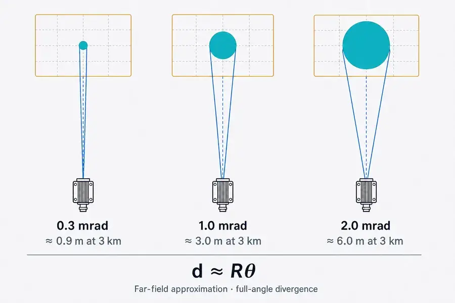
Optical integration
Spot size changes with distance
Beam divergence, target size, boresight, receiver field of view, and platform stability must be reviewed together to keep the illuminated spot on the intended target.
At 3 km:
- 0.3 mrad gives an approximate 0.9 m spot;
- 1.0 mrad gives an approximate 3.0 m spot;
- 2.0 mrad gives an approximate 6.0 m spot.
A narrower beam can improve target fill on a compact distant target, but only when:
- transmit alignment stays on the target;
- the receive field of view overlaps the illuminated area;
- platform motion and vibration are controlled;
- thermal drift does not move the axes;
- the pointing or scanning system has adequate angular accuracy.
This is why divergence, boresight, field of view, target size, and platform stability belong in the same design review.
1535 nm and 905 nm: choose the system, not the label
Lumexis focuses on 1535 nm erbium-glass modules where compact long-range pulsed measurement and a larger wavelength-level laser-safety design margin are important. That does not mean every 1535 nm product is automatically safe, or that 1535 nm is always the best technical or commercial choice.
| System factor | 1535 nm architecture | 905 nm architecture |
|---|---|---|
| Typical pulsed emitter | Erbium-glass source | Semiconductor laser diode |
| Typical detector family | InGaAs APD or related 1.5 μm detector | Silicon APD/SPAD or related silicon detector |
| Detector and component economics | Higher-cost 1.5 μm components and verification | Larger, mature silicon and diode supply ecosystem |
| Ocular interaction | Radiation above 1400 nm is strongly attenuated before reaching the retina, shifting the limiting tissue and allowing a different exposure budget under the standard5 | 905 nm can reach and be focused on the retina, so retinal exposure is a central design constraint |
| Safety statement | Classification still depends on accessible emission, pulse energy, pulse duration, repetition, aperture, divergence, exposure geometry, and measurement method | The same principle applies: classification belongs to the finished product and verified emission condition |
| Weather and wet surfaces | Performance can be affected by water absorption and adverse conditions; test the specific system | May have different transmission and wet-surface behavior, but fog, rain, and backscatter still reduce usable range |
| Best-fit decision | Long-distance professional systems where the 1.5 μm architecture, package, and safety design margin justify cost | Cost-sensitive or high-volume systems where the required range can be met with mature 905 nm components |
Laser classification is a product-level result. FDA guidance describes Class 1 as non-hazardous under the classified condition and notes that hazard can change when optical aids are involved.3 Lumexis should publish a Class 1, Class 1M, “eye-safe,” CE, or RoHS statement only when the exact finished configuration has supporting test and compliance documentation.
Read the data sheet like an integrator
Maximum range is conditional
Ask for:
- target dimensions and reflectivity;
- visibility and humidity;
- detection-probability or valid-measurement criterion;
- measurement mode and rate;
- window and alignment condition;
- whether the value is typical, minimum, or guaranteed.
Accuracy is not resolution
- Accuracy is the difference between reported distance and a traceable reference under stated conditions.
- Repeatability describes variation when the same condition is measured repeatedly.
- Distance resolution describes the ability to distinguish returns separated in range.
- Valid-measurement rate describes how often the system produces a result that passes its validity criteria.
A module can have metre-class absolute accuracy while using a different numerical value for multi-target separation. Do not use the terms interchangeably.
Measurement rate is not control-loop bandwidth
A 10 Hz range output does not automatically produce a 10 Hz closed-loop response. Command latency, acquisition time, filtering, packet transfer, timeout handling, host scheduling, and rejected returns all contribute to end-to-end behavior.
Average power is not peak power
Pulsed systems can have a modest average demand and a higher short-duration peak. The host supply should be reviewed for:
- startup and enable behavior;
- transient and peak current;
- cable drop and connector resistance;
- grounding and communication reference;
- standby, single-shot, and continuous modes;
- supply noise coupling into the receiver.
OEM integration guide
1. Optical window and aperture clearance
The host window becomes part of the optical system. Verify:
- clear aperture around both transmit and receive channels;
- wavelength-appropriate window material and anti-reflection treatment;
- window thickness, wedge, flatness, and surface quality;
- short and controlled air gap;
- separation or baffling that prevents transmit leakage into the receiver;
- contamination, condensation, coatings, and angle of incidence;
- final ranging performance with the production window installed.
Do not copy a generic window stack into production. Confirm the window requirement against the selected module, enclosure geometry, and order-specific optical review.
2. Mechanical datum and boresight
Define how the module’s optical axes relate to the host datum. The mount should retain alignment without loading the optics. Review:
- datum surfaces and tolerance stack;
- fastener preload and enclosure stiffness;
- thermal expansion and heat paths;
- vibration and shock paths;
- cable forces and service access;
- boresight verification before and after environmental stress.
3. Electrical interface
Lumexis modules are available with RS422 or TTL according to configuration.
- Use RS422 when cable length or electrical noise makes differential signaling valuable.
- Use TTL only when voltage levels, ground reference, cable length, and host logic are compatible.
- Confirm baud rate, command framing, measurement cadence, timeout, error handling, and power-enable behavior from the order-specific communication document.
- Do not publish or implement a protocol from an uncontrolled revision.
4. Receiver protection and strong returns
Very close, highly reflective, or specular targets can create strong returns. Establish a controlled test method and follow the selected module’s minimum-range and handling guidance. Do not point an unverified open module at close reflective surfaces during bench work.
5. Environmental enclosure
If the selected module is not hermetic, the host must control humidity, cleanliness, condensation, and contamination. The environmental rating of the finished instrument cannot be inferred from the operating-temperature line alone.
A verification plan for the finished instrument
Engineering prototype
- verify power-up, enable, and communication;
- test single and continuous ranging;
- confirm target-specific range at representative distances;
- check close targets and multiple surfaces under a controlled procedure;
- establish module-to-host boresight;
- record supply rail, current, timing, and packet behavior.
Design validation
- install the production optical window, baffle, cable, and mount;
- test representative target materials, sizes, and angles;
- repeat checks in bright background, low visibility, temperature, and humidity conditions relevant to the product;
- test before and after vibration or other mechanical stress;
- verify the host rejects stale, invalid, or out-of-range data safely.
Production validation
- define a golden configuration and controlled firmware/protocol revision;
- create optical-axis and functional test fixtures;
- record traceable pass/fail limits;
- verify range output with the finished enclosure;
- preserve serial, revision, and calibration records.
What to send Lumexis for a fast recommendation
Copy this checklist into your enquiry:
- application and host equipment;
- target type, dimensions, material, and expected reflectivity;
- normal and maximum working distance;
- required minimum distance;
- visibility, weather, temperature, humidity, and contamination;
- allowable module dimensions, mass, and receive aperture;
- accuracy, measurement rate, and target-selection requirement;
- supply voltage and peak-power limit;
- RS422 or TTL preference, cable length, and host controller;
- window material, position, and available clear apertures;
- sample quantity, annual volume, and target programme timing.
Lumexis — precision laser sources, engineered for the real world.
Frequently asked questions
What is a laser rangefinder module?
A laser rangefinder module is an integrated optical-electronic subsystem that emits a laser pulse, collects the target return, measures the Time-of-Flight interval, and sends distance data to a host system. It typically includes the source, transmit and receive optics, detector, signal chain, timing, control, and communication interface.
How does a 1535 nm laser rangefinder module measure distance?
It measures the round-trip time between a transmitted pulse and the detected return. One-way distance is calculated as R = cΔt / 2. The wavelength determines the source, optics, detector, atmospheric interaction, and safety evaluation, but the distance calculation still comes from time.
Is a laser rangefinder module the same as LiDAR?
Not necessarily. A rangefinder module provides one or more range returns along its measurement direction. A scanning or imaging LiDAR adds angular sampling and processing to create a 2D or 3D dataset.
Why can two targets have different maximum ranges with the same module?
Target size, reflectivity, angle, surface roughness, beam fill, atmosphere, and background all change the useful return. A large diffuse structure and a small low-return target are not equivalent test conditions.
How does beam divergence affect the result?
Divergence determines how quickly the footprint grows with distance. A smaller footprint can put a larger fraction of the pulse on a compact target, but it also demands tighter pointing, boresight, and stability.
Why does receive aperture matter?
Receive area scales with the square of clear-aperture diameter. A larger aperture can collect more return energy, but it increases optical and mechanical demands and does not correct poor target fill, misalignment, or atmospheric loss.
Is 1535 nm automatically eye-safe?
No. The wavelength changes how radiation interacts with the eye and can provide a larger design margin than 905 nm under relevant exposure conditions, but laser class depends on the finished product’s accessible emission and test method. Publish an eye-safety or Class 1 claim only with supporting compliance evidence for the exact configuration.
Should I choose 1535 nm or 905 nm?
Choose from the system requirement. 905 nm often offers lower component cost and a mature silicon detector chain. A 1535 nm architecture can be attractive when long-distance pulsed performance and wavelength-level safety design margin justify the higher-cost source and InGaAs receiver.
What is the difference between accuracy and distance resolution?
Accuracy compares the reported result with a reference. Distance resolution describes how closely spaced two returns can be while remaining distinguishable. They are different specifications and may have very different values.
What should be tested after installing the module?
Retest with the final window, baffle, mount, cable, supply, firmware, and enclosure. Verify communication, boresight, target-specific ranging, close returns, environmental behavior, and performance before and after mechanical stress.
Technical references
Application references
- U.S. Geological Survey, “Lidar Applications and Business Uses Factsheets.”
- U.S. Geological Survey, “Light Detection and Ranging (LiDAR).”
- NASA Airborne Science Program, “Airborne Laser Terrain Mapper Experiment.”
NASA Technical Reports Server, “NASA Technical Paper 1138,” Appendix B range-equation treatment, and “Laser Range Measurement,” receiver area, target reflectivity, and range relationships. Accessed 2026-07-26. ↩
R. Rasshofer et al., “Light Transmission in Fog: The Influence of Wavelength on the Extinction Coefficient,” Applied Sciences 9(14), 2019; and S. Zhao et al., “Advances in LiDAR Hardware Technology: Focus on Elastic LiDAR for Solid Target Scanning,” Sensors 24(22), 2024. Accessed 2026-07-26. ↩
U.S. Food and Drug Administration, “Laser Products and Instruments” and “Laser Products — Conformance with IEC 60825-1 Ed. 3.” Accessed 2026-07-26. ↩
Hamamatsu Photonics, “InGaAs APDs,” product family for LiDAR detection at 1550 nm. Accessed 2026-07-26. ↩
C. A. Rockwell et al., “Evaluation of the potential eye hazard at visible wavelengths of the supercontinuum generated by an ultrafast NIR laser in water,” Journal of Biomedical Optics 26(2), 2021. The discussion summarizes the change from retinal to anterior-eye limiting tissue above 1400 nm. Accessed 2026-07-26. ↩