
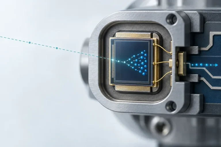








A laser rangefinder can look like a simple black box: aim at a surface, trigger a measurement, and read a distance. For an OEM system, the difficult part is not the arithmetic. It is preserving a usable optical return while the target, ambient light, temperature, mounting, and host timing all change.
That is why two modules with similar headline range figures can behave very differently once they are installed. The measurement depends on the complete signal chain, not only the transmitter.
How does a laser rangefinder work? A pulsed laser rangefinder emits a controlled optical pulse, detects a fraction of the reflected return, measures the round-trip delay, and calculates distance as d = c × t / 2. The transmitter, optics, detector, timing electronics, signal-processing rules, and test conditions together determine whether that distance is reliable.
How does a laser rangefinder work? Start with a controlled pulse
The measurement starts when the electronics define a repeatable transmit event. A driver excites the laser source, and the transmit optics shape the outgoing beam toward the intended measurement area. In a pulsed system, the reference can be tied to a monitored launch event or another defined timing point in the instrument.
The output is not a guaranteed distance result by itself. Beam divergence determines the footprint at the target, so the footprint can include the intended surface plus nearby edges, vegetation, hardware, or background. The optical design must therefore match the target size, working distance, and allowed alignment tolerance.
NIST defines the speed of light in vacuum as exactly 299,792,458 m/s. The simple range equation uses the round-trip time, which is why the distance is divided by two. In a finished instrument, the relevant timing estimate also reflects the propagation medium, optical path, detector response, and calibration method.
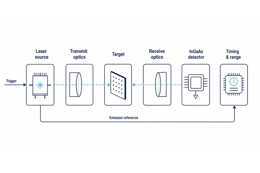
Typical pulsed time-of-flight signal chain. The dashed optical paths are conceptual and do not depict a specific Lumexis module architecture.
Step 2: Let the target and environment shape the return
When the pulse reaches a target, only part of the transmitted light becomes a useful return. Surface reflectance, angle, size, texture, and the fraction of the footprint that actually lands on the target all matter. Atmospheric transmission, contamination on a protective window, and ambient illumination can further change what reaches the receiver.
This is the first reason an OEM should read range claims with their test conditions attached. A result measured against a large, bright, normal-incidence target does not automatically predict performance on a darker, angled, smaller, or partially obscured target. For a fixed receiver aperture, the available return also changes with distance and target behavior.
The answer is not to specify only a stronger source. System performance is a balance among transmit optics, receiver aperture and field of view, detector sensitivity, electronic bandwidth, signal processing, thermal behavior, and the allowed power budget. Our laser technology approach starts from those interfaces because the ranging result belongs to the whole instrument.
Step 3: Detect the return without confusing it for noise
Receive optics collect a small returned fraction and place it on a detector. The analog front end conditions that electrical signal; timing logic then estimates when the return occurred. Depending on the architecture, the system may apply thresholds, correlation, pulse-shape checks, repeated measurements, or validation rules before it reports a distance.
Return amplitude is important because a fixed decision threshold can make a strong and weak pulse appear to arrive at slightly different times. Engineers often call that amplitude-dependent shift timing walk. Noise, background light, receiver saturation, electrical ringing, and multipath reflections can introduce other failure modes, so a rangefinder needs an acceptance rule that fits the target and environment.
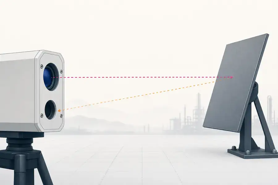
Conceptual return-signal context: target condition and optical geometry influence the usable signal at the receiver. No performance data are implied.
Step 4: Convert timing into a distance and validate it
For direct time-of-flight ranging, the processor turns the measured delay into distance using the round-trip relationship. The equation is compact; the implementation is not. The instrument needs stable time references, a defined pulse-width convention, a documented detector and receiver bandwidth, and calibration that covers the intended operating conditions.
Many engineering disputes are really test-definition disputes. Ask whether the figure was measured on a single target or a population, what the target reflectance and geometry were, which distance and ambient conditions were used, whether the reporting rate changed the operating point, and what the system does with marginal returns. Those questions make a datasheet much more useful than a bare maximum-range number.
For civil infrastructure inspection, industrial sensing, and scientific instruments, it is also useful to establish how the host receives a measurement: interface framing, update behavior, validity flags, warm-up behavior, and fault handling. Our engineering services focus on that transition from a component-level measurement to a dependable system-level function.
What a laser rangefinder module needs from the host system
A module does not operate in isolation after it is mounted. The mechanical datum affects boresight and vibration behavior. The enclosure window affects transmission and stray light. The electrical supply and grounding affect the driver and receiver environment. The host firmware affects when the system requests a result and how it handles no-return or ambiguous-return cases.
Before committing a design, make the integration review concrete:
- Define the target set: minimum size, expected reflectance range, angular variation, and working distances.
- Define the optical envelope: transmit footprint, receiver field of view, window material and cleanliness plan, and internal stray-light controls.
- Define the electrical and timing interface: supply limits, trigger or command behavior, response latency, reporting frame, and error states.
- Define qualification evidence: burn-in approach, temperature cycling, alignment retention, and the measurements repeated before and after environmental exposure.
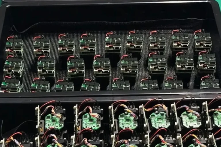
This is where a supplier should contribute more than a brochure. At Lumexis, our team can connect optical and optomechanical design, electronics and firmware, weak-signal ranging algorithms, thermal design, and test-method development. The production flow also includes incoming inspection, chip test, assembly, fiber coupling and alignment where applicable, sealing, aging screening, and final performance testing.
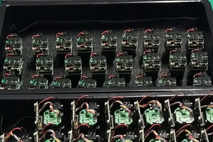
Representative module assembly trays used as production context. The image supports process discussion only and does not state a product specification or qualification result.
How to judge whether the reading is dependable
Use repeatable application tests rather than one favorable demonstration. Run the intended target surfaces and angles, include the expected background conditions, and record the full operating point: supply, temperature, measurement rate, target distance, optics configuration, and firmware revision. If an output seems inconsistent, preserve the raw conditions before changing the module or the algorithm.
That discipline also creates a clearer supplier conversation. When you share the target definition, mechanical envelope, interface, update requirement, and environmental needs, we can evaluate the trade-offs early. Explore our system solutions or contact our engineers with those inputs to start a technical review.
FAQ
Does every laser rangefinder use time of flight?
No. Many laser rangefinders use direct pulsed time of flight, but distance can also be inferred from modulated or phase-based optical signals, triangulation, or other architectures. The relevant question is which method the module uses and how its target conditions, ambiguity limits, timing, and calibration fit the application.
Why can the same target give different distance readings?
The return signal can change with surface reflectance, angle, footprint placement, background illumination, atmospheric conditions, and optical-window condition. Receiver noise, timing walk, threshold behavior, multipath, and the measurement-selection algorithm can also change the reported result. A controlled test log is the fastest way to identify the cause.
Does a narrower beam always improve ranging?
Not automatically. A narrower beam can reduce unwanted background within the footprint, but it also increases pointing and alignment sensitivity. The useful divergence depends on target size, distance, motion, mounting tolerance, and the receiver geometry. Specify the full optical task before choosing the beam geometry.
What should be included in an OEM range test?
Document the target material, reflectance behavior, size, angle, distance, ambient conditions, module temperature, power conditions, repetition or measurement rate, optical window configuration, firmware revision, and pass/fail rule. This turns a demonstration into evidence that another engineering team can reproduce.
Can a laser rangefinder module report more than one return?
Some ranging architectures and signal-processing schemes can distinguish or select among returns from different surfaces. The actual behavior depends on the receiver, timing method, pulse and detection strategy, firmware, and the geometry of the application. Confirm the selection logic and its test conditions with the module supplier.
References
- NIST, Definitions of the SI Base Units — fixed value of the speed of light used in the distance relation.
- Hamamatsu Photonics, Measuring Distance with Light — pulsed and phase-based distance-measurement context, target and aperture factors.
- P. Palojärvi, Pulsed Time-of-Flight Laser Range Finder Techniques for Fast, High Precision Measurement Applications — receiver bandwidth, pulse timing, and industrial ranging considerations.
- Z. Ye et al., The Short-Range, High-Accuracy Compact Pulsed Laser Ranging System — time-of-flight equation and return-signal considerations.