
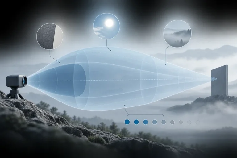
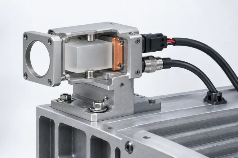
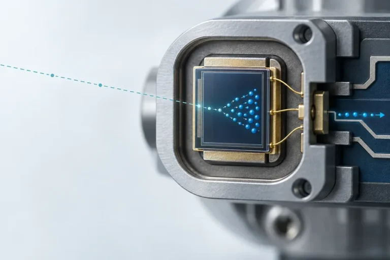




A 15 nm difference looks small on a spectrum, so it is tempting to treat 1535 nm and 1550 nm sources as interchangeable. That shortcut can break the optical filter match, change the source architecture, invalidate a calibration, or force a new qualification cycle after the enclosure is already fixed.
The important decision is not which number is larger. It is whether the complete transmitter, receiver, optics, environment, and production evidence fit the same system requirement.
In a 1535nm vs 1550nm laser comparison, neither wavelength is universally better for rangefinding. Both sit in the 1.5 µm region and can use InGaAs-class receivers. The practical difference usually comes from the chosen source architecture, pulse format, optical-filter match, component ecosystem, thermal behavior, and validation evidence—not from the 15 nm separation alone.
1535nm vs 1550nm laser: start with architecture, not the label
The two wavelengths are close, but engineering teams often encounter them in different source platforms. Compact 1535 nm transmitters are commonly associated with diode-pumped Er:Yb glass and passively Q-switched microchip cavities. Research on a specific Er:Yb phosphate-glass microchip measured a gain spectrum that supported lasing near 1535 nm and documented wavelength movement with pump thermal loading. That result is evidence for one material and cavity, not a universal rule for every 1535 nm source.
Sources near 1550 nm are often associated with fiber, amplifier, and telecom-component ecosystems. They can support pulsed ranging architectures, but “1550 nm” does not tell you whether the source is a direct emitter, a bulk laser, a fiber oscillator, or a seeded amplifier. Likewise, 1535 nm is not limited to one gain medium or package.
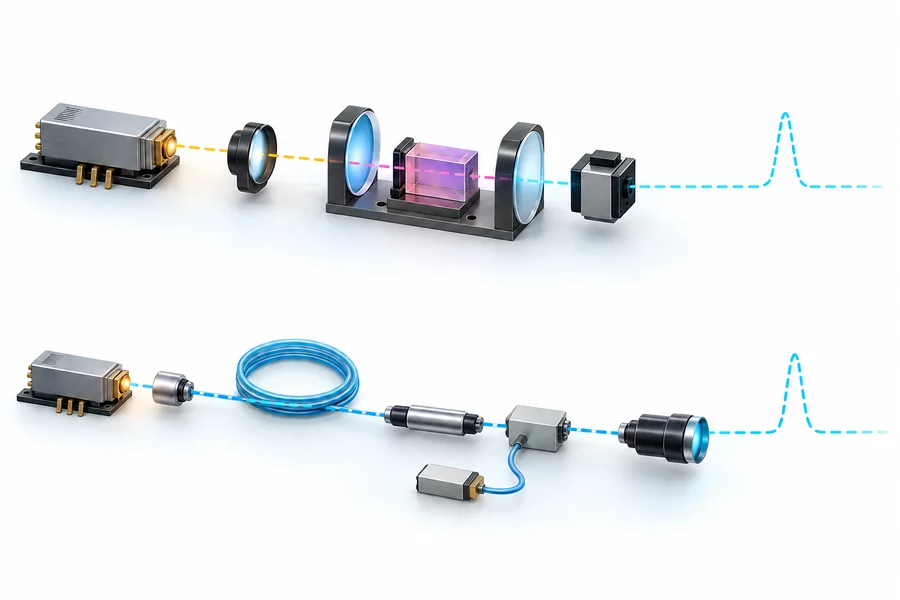
Ask for the architecture behind the wavelength. A useful source specification states pulse energy, pulse-duration definition, repetition rate, center wavelength and tolerance, beam conditions, operating temperature, drive point, and where the measurement was taken. Our guide to the erbium-glass laser rangefinder explains the source, transmitter, and complete-instrument boundaries in more detail.
The receiver family may be shared, but the optical stack is not automatic
InGaAs photodiodes are a relevant detector family across the 1.5 µm region. NIST uses InGaAs standards across a much wider near-infrared span than these two wavelengths, which supports the broad material-family fit. It does not mean that any two detector parts have identical responsivity, noise, bandwidth, gain, temperature behavior, or calibration at 1535 nm and 1550 nm.
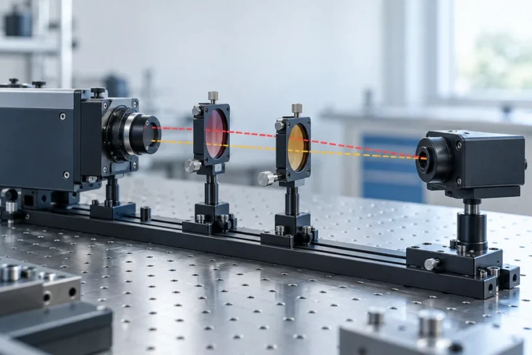
The optical filter is often the more immediate integration issue. A narrow receiver filter selected to reject background light has a center wavelength, bandwidth, angle sensitivity, temperature behavior, and manufacturing tolerance. A source shifted by 15 nm may sit outside the intended filter window even though both wavelengths use the same detector material.
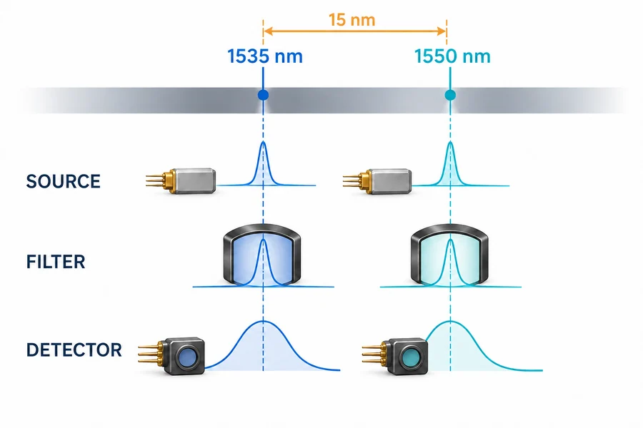
Review the whole spectral stack:
- source center wavelength and drift across the specified drive and temperature range;
- transmitter and receiver coating bands at the real incidence angles;
- receiver-filter center, bandwidth, blocking range, and tolerance;
- detector responsivity, noise, gain, and calibration at the selected wavelength;
- window transmission and any wavelength-dependent contamination or aging effect.
A broad detector response cannot rescue a mismatched narrow filter. It also cannot establish range on its own. The received signal still depends on transmit energy, divergence, target condition, atmospheric path, receiver aperture, optical loss, timing, and processing.
What the 15 nm difference does not prove
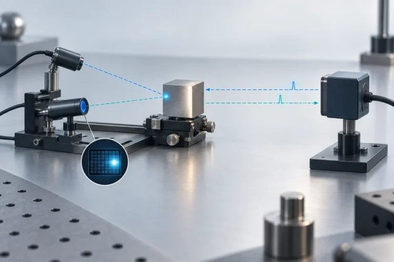
It does not prove a longer measurement range. A range claim belongs to a defined target, distance criterion, visibility or atmospheric condition, optical configuration, receiver state, and success rule. Compare two modules only when those conditions are matched. Our laser rangefinder module datasheet guide lists the conditions that should sit beside each performance value.
It does not prove a laser safety classification. IEC 60825-1 applies classification to the accessible emission of a laser product under defined operating, maintenance, service, and failure conditions. Both wavelengths belong to the same broad 1.5 µm engineering discussion, but the exact pulse pattern, beam geometry, aperture, optics, enclosure, and product state still matter. The separate article on why 1550 nm is described as eye-safe covers that hazard mechanism without treating wavelength as a product certificate.
It does not prove better atmospheric transmission. Molecular absorption varies across wavelength and with path conditions. HITRAN provides line-by-line spectroscopic parameters for modeling gaseous absorption, including water-vapor effects, but a useful prediction still needs the path length, pressure, temperature, humidity, aerosol condition, source spectrum, and receiver band. For a real civil or industrial path, model and test both exact configurations instead of repeating a blanket weather claim.
Compare the two options with a controlled evidence table
Use the same questions for both candidates. This prevents a mature 1535 nm module from being compared with an unqualified 1550 nm source, or a complete 1550 nm instrument from being compared with a bare 1535 nm transmitter.
| Decision area | Evidence to request for 1535 nm | Evidence to request for 1550 nm |
|---|---|---|
| Source architecture | Gain medium, cavity or fiber path, pulse-generation method, drive point | Gain medium, oscillator/amplifier path, pulse-generation method, drive point |
| Spectral control | Center wavelength, tolerance, drift, linewidth definition | Center wavelength, tolerance, drift, linewidth definition |
| Receiver match | Filter band, coating band, InGaAs detector operating point | Filter band, coating band, InGaAs detector operating point |
| Range statement | Target, path, optics, rate, temperature, acceptance criterion | The same matched conditions and acceptance criterion |
| Product review | Accessible output and exact optical configuration | Accessible output and exact optical configuration |
| Production evidence | Alignment method, screening, traceability, change control | Alignment method, screening, traceability, change control |
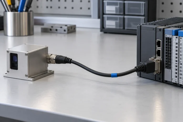
The current Lumexis 1535 nm laser rangefinder module provides a model-specific starting point. Treat its controlled specification as evidence for that model only. Do not transfer a wavelength, range, or environmental statement to another source architecture without a matched test record.
A late wavelength change is a system change
Changing from 1535 nm to 1550 nm after design freeze can affect more than a source part number. The transmitter optics may need a different coating band. The receiver filter must be re-centered or re-qualified. Detector calibration, timing thresholds, temperature compensation, stray-light control, and window behavior may need review. Firmware identifiers and production test limits may also change.
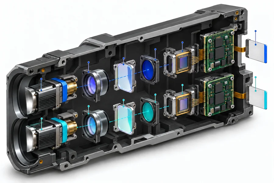
Treat the change as a controlled configuration revision. Repeat spectral verification, pulse characterization, boresight and alignment checks, target-conditioned range testing, background-light testing, temperature points, and the finished-product accessible-emission review. Keep the old and new evidence packages separate so production cannot mix components that look compatible but are spectrally mismatched.
LUMEXIS supports this work through optical and optomechanical design, electronics and firmware, weak-signal ranging logic, thermal management, and test-method development. Our Wuxi engineering and commercial office works with a 14,000-square-meter Taizhou manufacturing base, where controlled assembly, optical alignment, hermetic sealing where applicable, aging screening, temperature cycling, and final performance testing support repeatable builds. See our ranging laser source solution and engineering service for the relevant integration path.
Frequently asked questions
Are 1535 nm and 1550 nm interchangeable in a laser rangefinder?
Not automatically. The detector material may cover both wavelengths, but the source, filter, coatings, window, calibration, and qualification record may be centered on one exact band. Treat a change as an optical configuration revision and verify the complete transmit and receive paths.
Is 1535 nm always an erbium-glass laser?
No. Er:Yb glass is a common compact source route near 1535 nm, but wavelength does not uniquely identify the gain medium or cavity. Request the actual source architecture, pulse-generation method, operating point, and controlled spectral data.
Is 1550 nm always a fiber laser?
No. Fiber and telecom-derived components are common near 1550 nm, but other source architectures are possible. The wavelength label cannot establish pulse energy, beam quality, package size, thermal behavior, or production maturity.
Can the same InGaAs detector be used at both wavelengths?
Possibly, if the exact detector, front end, filter, and calibration meet the requirement at both operating points. Verify responsivity, noise, bandwidth, gain, temperature behavior, and filter transmission for the selected parts rather than relying on the detector-material name.
Which wavelength gives longer range?
Neither wavelength guarantees longer range by itself. Compare pulse conditions, divergence, target definition, atmosphere, receiver aperture, optical losses, detector behavior, timing, processing, and the acceptance rule under matched tests.
Do both wavelengths automatically meet the same product class?
No. Product classification depends on accessible emission and the complete operating configuration. A 15 nm separation does not transfer evidence from one source, optic, enclosure, or operating mode to another.
References
- Z. P. Cai et al., “Investigation of red-shift of an Er:Yb:Kigre phosphate glass microchip laser at 1535 nm due to pump thermal loading”, Optica Publishing Group, 2001.
- NIST, Spectral Comparator Facilities, including the Vis/NIR detector-calibration range and InGaAs standards.
- IEC, IEC 60825-1:2014 preview—Safety of laser products, Part 1.
- I. E. Gordon et al., The HITRAN2024 Molecular Spectroscopic Database, Journal of Quantitative Spectroscopy and Radiative Transfer, 2026.
Evaluating a 1535 nm or 1550 nm architecture? Send our applications engineers the target and path conditions, pulse requirement, optical envelope, filter band, operating temperature, interface, volume, and required validation evidence. We can recommend a standard configuration or scope a custom or private-label review with its own qualification plan and lead time.