

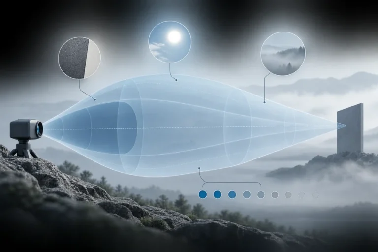

A rangefinder can look stable on an open bench and then drift, miss targets, or report the background after it is installed. The module may not be defective. The protective window, alignment, power rail, target geometry, temperature, or host processing may have changed the measurement chain.
That is why teams asking how to improve laser rangefinder accuracy should resist changing several settings at once. A correction that helps one target at one distance can hide the real fault and make performance less predictable elsewhere.
To improve laser rangefinder accuracy, first classify the error as bias, poor repeatability, nonlinearity, invalid returns, or wrong-target selection. Then control target and beam geometry, remove optical and electrical instability, manage temperature, filter only valid returns, calibrate across the operating envelope, and verify the final assembly against a traceable reference.
How to improve laser rangefinder accuracy: start with the failure mode
Accuracy is closeness to a reference value. Repeatability is how tightly repeated measurements cluster under the same conditions. Resolution is the smallest reported increment. These are related, but improving one does not guarantee improvement in the others.
A stable offset suggests a different investigation from a wide measurement spread. Range-dependent error points toward nonlinearity or a condition-dependent timing effect. Intermittent zero values, stale values, or sudden jumps may be interface or return-validation problems rather than calibration errors. Our guide to laser rangefinder accuracy specifications explains how to read these terms before setting acceptance limits.
Begin with a baseline log that preserves raw distance, validity or status fields, temperature, supply state, configuration, target, reference distance, and timestamp. Do not discard failed readings before you understand them. A clean average built after silent removal of inconvenient results can conceal a reliability problem.
| Observed symptom | First checks | Avoid as the first response |
|---|---|---|
| Stable offset | Reference setup, datum, fixed delay, calibration state | Increasing averaging |
| Wide random spread | Return strength, ambient light, power noise, timing jitter | Applying one offset |
| Error changes with distance | Beam fill, target/background mix, nonlinearity, calibration model | Correcting only one distance |
| Dropouts or invalid returns | Target return, window loss, receiver saturation, status handling | Replacing invalid values with the last valid range |
| Sudden near/far jumps | Multiple targets, edges, reflections, first/last-return logic | Averaging unlike returns together |
Improve target return quality before changing algorithms
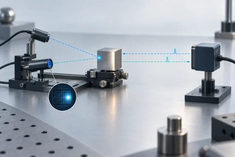
The receiver cannot estimate arrival time reliably if the intended return is weak, distorted, or mixed with another surface. Target reflectivity matters at the transmitter wavelength, not only in visible color. A dark-looking material may return useful near-infrared energy, while a shiny surface can direct most of the reflection away from the receiver.
Target size and angle matter too. As the beam expands with distance, part of the spot may fall beyond a small target. If the spot crosses an edge, the receiver can see returns from two depths. The selected distance then depends on return strength and the module’s detection logic, not merely on the center of the aiming mark.
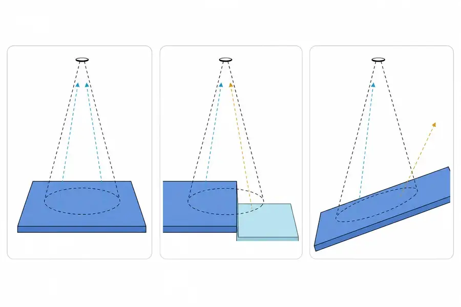
Use representative target materials in the test plan rather than relying on one convenient white panel. Include the smallest intended target, realistic surface angles, and backgrounds that can enter the beam footprint. For the broader wavelength and detector tradeoffs behind target response, see our laser rangefinder wavelength selection guide.
Fix the window, alignment, and boresight as one optical system
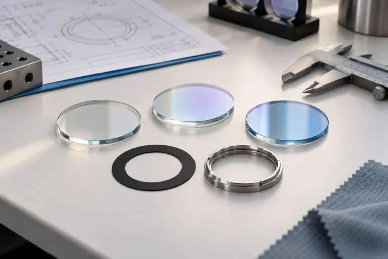
The host enclosure becomes part of the optical instrument. A protective window can reduce transmission, create a near-field reflection, collect contamination, or redirect stray light into the receive path. Its material, coating, tilt, clear aperture, spacing, and mounting stress all deserve review.
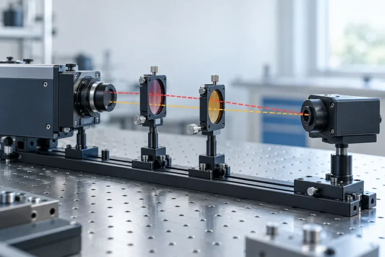
Test the module first without the final window, then repeat with the complete enclosure while holding the target and reference distance constant. If the error or invalid-return rate changes, isolate window angle, surface cleanliness, aperture clipping, and transmitter-to-receiver isolation one variable at a time. Our article on optical crosstalk in rangefinder integration covers this failure mode in more detail.
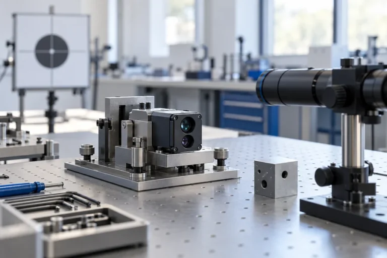
Boresight stability is equally important. The emitter, receiver field of view, host aiming reference, and mechanical datums must remain aligned after fastening, vibration, and temperature change. A narrow beam may help separate close targets, but it also makes angular error and platform motion more consequential. Treat divergence and alignment as a system tradeoff, not independent datasheet rows.
Stabilize power, timing, and temperature before calibrating
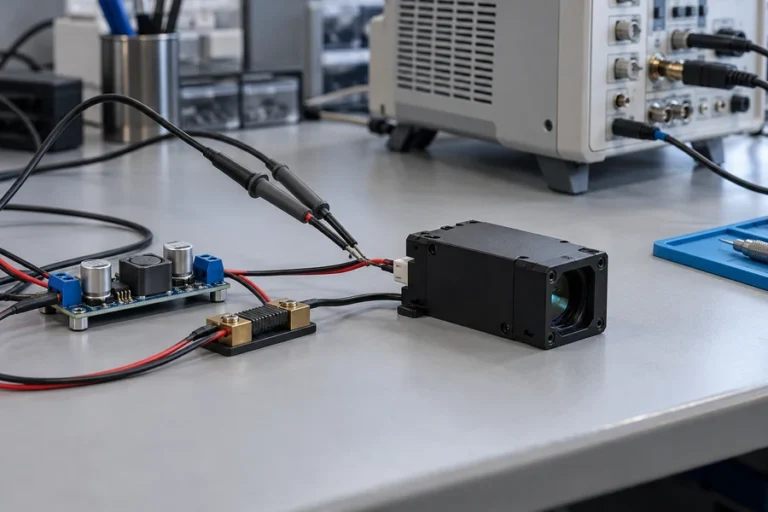
A correction model cannot repair an input that changes unpredictably. Capture supply voltage at the module during acquisition, including startup and burst behavior, rather than checking only the nominal rail with the sensor idle. Review grounding, cable drop, connector resistance, and conducted noise from nearby loads.
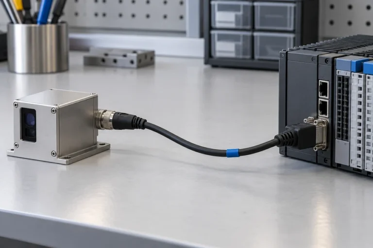
Also verify that the host reads complete frames, respects protocol timing, and handles status bytes correctly. A serial link that drops or combines bytes can create implausible ranges even when the optical measurement is sound. The current laser rangefinder interface guide provides a useful framework for framing, timing, and error handling.
Temperature can change the optical, detector, oscillator, and mechanical state. Define warm-up behavior, record module and enclosure temperature where practical, and compare results across the actual operating envelope. If a stable temperature-dependent bias remains after the hardware is stable, it may be a calibration candidate. If the spread or dropout rate changes sharply, investigate signal margin and mechanics before fitting a correction.
Use filtering to improve precision, not to hide bias
Averaging repeated valid measurements can reduce random spread when the target and sensor are stationary. It does not remove a systematic offset, fix a window reflection, or turn two different target returns into one correct answer. A longer averaging window also adds latency and can blur a moving target or platform transition.
Validate each return before it enters the filter. Preserve status information, define plausible rate-of-change limits for the application, and decide how the host behaves when no trustworthy measurement is available. Reporting “invalid” is often safer and more useful than holding an old value without a flag.
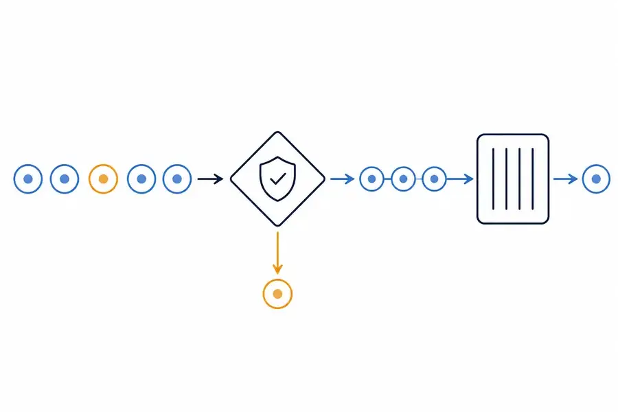
Filter settings should be tested with the dynamics that matter to the product. A stationary laboratory target can make an aggressive filter look excellent, while the same filter lags during UAV altitude changes or moving industrial inspection. For application-level architecture and module selection, the Lumexis laser ranging solution connects the optical source, receiver, processing, and integration requirements.
Calibrate across distance and conditions, then use holdout points
Calibration compares the rangefinder output with a better-characterized reference and estimates a correction within a defined scope. A single offset can be appropriate for a stable fixed delay, but it should not be assumed to correct the whole range. Distance-dependent, temperature-dependent, and target-dependent behavior may require a different model—or a hardware fix.
Use several application-relevant distances and repeat measurements at each point. Divide them into calibration points and holdout points that are not used to fit the correction. Verify the residual error on those holdout points and repeat the test across representative targets and temperatures.
Measurement uncertainty belongs in the acceptance decision. Record the reference uncertainty, setup repeatability, alignment method, target definition, environmental state, and calculation method. A correction that appears smaller than the combined uncertainty may not demonstrate a meaningful improvement.
Validate the final assembly with a production-relevant matrix
The final test should include the production enclosure, protective window, cable, power supply, host firmware, interface settings, and mounting datums. Define acceptance criteria before collecting data, including what counts as an invalid return and whether a repeat is allowed.
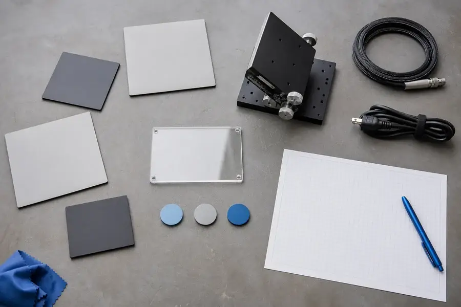
A practical matrix can cover near, middle, and far application distances; low- and high-return targets; normal and oblique angles; controlled and high ambient light; cold, room, and hot operating states; static and representative motion; and both open-module and final-enclosure configurations. The exact levels must come from the product requirements, not a generic internet checklist.
Keep the configuration version, raw results, analysis script, reference record, and fixture definition together. Retest after changes to the window, mounting, power architecture, firmware, filtering, or calibration table. Lumexis applications engineers can support module selection, integration, validation, and troubleshooting through our engineering service, including custom and private-label requirements where appropriate.
FAQ
Does averaging improve laser rangefinder accuracy?
Averaging can improve repeatability when measurements contain random noise and every return represents the same stationary target. It does not remove stable bias, correct range-dependent error, or resolve mixed targets. Test the filter with real motion and latency requirements, and reject invalid returns before averaging.
Can one offset calibration fix all distance errors?
Only if the error is demonstrably stable and approximately constant across the intended range and conditions. Verify that assumption at several distances and temperatures. If residual error changes with distance, target, or temperature, investigate the physical cause and use a justified model rather than forcing one offset.
Why does a dark or angled target change the result?
The receiver depends on returned optical energy and waveform shape. Reflectivity at the laser wavelength, surface texture, incidence angle, beam fill, and background can change the return. A weak or mixed return can increase spread, cause dropouts, or shift which surface the processing selects.
Can a protective window reduce accuracy?
Yes. A window can add loss, clipping, contamination, ghost reflections, and alignment sensitivity. Compare open-module and final-enclosure results under the same controlled setup. Review material, coating, tilt, spacing, clear aperture, cleanliness, and mechanical stress before compensating in software.
How many distances should an OEM accuracy test include?
There is no universal count. Use enough points to cover the application range, expose nonlinearity, and reserve independent holdout points for verification. Include representative targets and environmental states. The test design should be justified by the product’s risk and acceptance limits.
If you are diagnosing an accuracy gap, send Lumexis your target materials, distance bands, enclosure and window geometry, interface, update rate, operating temperature, and current validation method. Our team can review the measurement chain and recommend a standard module or a custom integration path. Discuss the application with an engineer.
References
- International Organization for Standardization, ISO 16331-1:2017 — Performance of handheld laser distance meters.
- National Institute of Standards and Technology, Measurement Uncertainty.
- J. M. P. Nascimento et al., Methods of Precise Distance Measurements for Laser Rangefinders with Digital Acquisition of Signals, *Sensors*, 2021.
- M. Lindner and A. Kolb, Time-of-Flight Sensor Calibration for Accurate Range Sensing, *Computer Vision and Image Understanding*, 2011.