








At Lumexis, we design and manufacture laser rangefinder modules for civil, industrial, and scientific ranging systems. There is no best wavelength in isolation: a program can have a good source choice and still miss its range target because the return signal, aperture, receiver, temperature, optics, or test method was treated as an afterthought. That is especially common when a wavelength decision is made before the target and use conditions are written down.
The better question is not “which wavelength wins?” It is “which architecture can repeatedly measure the required target inside the finished instrument’s optical, electrical, commercial, and verification constraints?”
The best wavelength for laser rangefinder design is the one that satisfies the complete measurement requirement with a defensible transmitter, receiver, optical path, accessible-emission review, and production plan. For many compact systems, 905 nm may align with available silicon-receiver architectures. For some longer-path or open-air designs, a 1.5 µm approach may be appropriate, but it brings different source, receiver, and integration questions. Validate the system, not the wavelength label.
To identify the best wavelength for laser rangefinder integration, compare candidate architectures against the same conditioned measurement requirement and verification plan.
Best wavelength for laser rangefinder selection starts with the target
Write a measurement-condition sheet before comparing sources. It should specify the target material and reflectance, target size, range window, incidence angle, measurement rate, ambient light, atmosphere, operating temperature, supply limit, host-instrument aperture, and output interface. Without these conditions, a distance claim cannot be compared fairly.
This also protects the procurement team. A supplier can quote a result for a reflective target, a particular visibility condition, a specific repetition rate, and a particular receiver configuration. Your product may not use any of those conditions. The useful question is whether the supplier can state and reproduce the test method for the configuration you need.
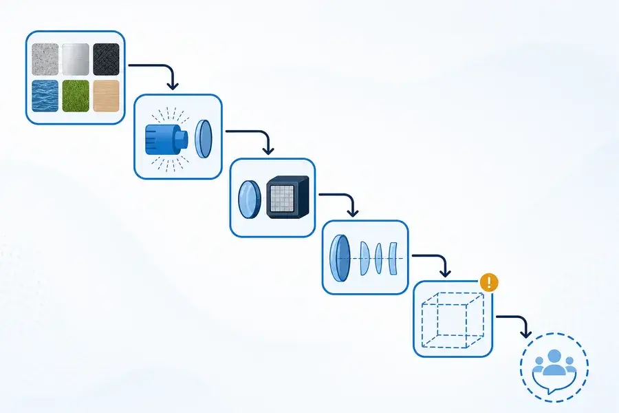
Caption: Conceptual selection flow. It starts with the conditioned measurement task because wavelength is one decision within a complete ranging architecture.
Compare the transmitter and receiver as one optical chain
The selected wavelength affects the transmitter technology and the receiver materials that are practical. At 905 nm, silicon-based detector options are commonly available. In the 1.5 µm region, receiver designs commonly consider InGaAs-class detectors because silicon is not generally responsive there. That is an architecture shift, not a single line on a parts list.
The receiver choice affects front-end noise, bias, optical filtering, sourcing, and calibration. The transmitter choice affects pulse format, drive electronics, thermal design, packaging, beam diameter, and divergence. In a pulsed system, pulse energy, duration, and repetition rate must be reported together because they set the average-power and approximate peak-power context. A datasheet without its operating point is an incomplete design input.
Use the same discipline for optical interfaces. A smaller divergence may change spot size at distance, but it is not automatically better if pointing tolerance, target size, or near-field behavior becomes the limiting factor. Our article on laser rangefinder module types helps separate architecture categories from application claims.
Treat accessible output as a separate requirement
The wavelength region informs the optical-hazard conversation, but it does not classify an instrument. RP Photonics explains that wavelengths beyond approximately 1.4 µm are absorbed more strongly in the front of the eye before reaching the retina, while also noting that sufficient power or pulse energy can still damage the cornea. The accessible output of the finished product remains the relevant engineering boundary.
Review the actual apertures, windows, beam-shaping optics, service access, measurement modes, and host enclosure. FDA guidance on laser-product conformance gives useful standards context; it should not be replaced by a source label or a component marketing statement. If the application needs a detailed framework, begin with our laser-rangefinder safety review guide.
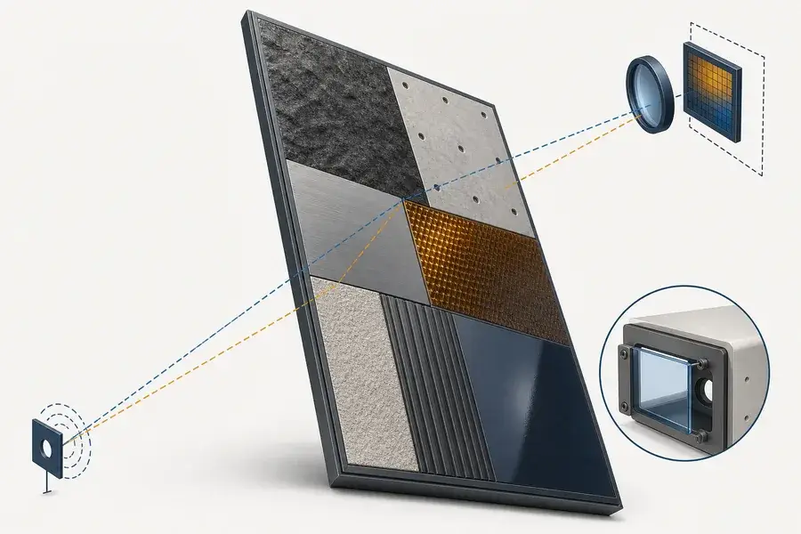
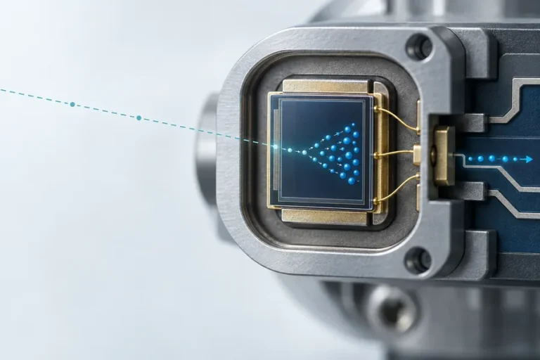
Caption: Conceptual target-conditioned return-path view. Dashed paths encode invisible wavelengths for explanation and do not show a product design or a performance result.
Use environment as an input, not a generic weather claim
Atmospheric transmission and background light vary with wavelength, path length, particle distribution, water vapor, optics, and receiver filtering. Avoid broad claims that one band “wins” in all fog, rain, haze, or sunlight. Instead, identify the environmental condition that dominates your use case and model or test it at the intended operating point.
The same approach applies to target materials. A bright reference target is useful for calibration, but it does not establish performance on dark, angled, wet, or structured surfaces. Specify the target condition in the RFQ and keep it in the production acceptance plan. A rangefinder is an optical link, so the target and atmosphere belong in the selection decision.
Build a decision matrix your team can defend
Use a matrix that forces every architecture to answer the same questions:
| Evaluation area | What to define before choosing |
|---|---|
| Measurement task | Target reflectance, size, range, rate, and repeatability need |
| Optical link | Transmit divergence, receiver aperture, filtering, alignment, and return margin |
| Source path | Pulse conditions, drive, thermal interface, packaging, and availability |
| Receiver path | Detector material, noise, biasing, bandwidth, calibration, and supply risk |
| Finished instrument | Accessible apertures, enclosure, windows, operating modes, and use conditions |
| Production | Test method, traceability, burn-in, temperature cycling, and change control |
This matrix reveals whether a low first-cost option creates qualification risk later, or whether a more complex optical chain has a measurable payoff. It also makes supplier conversations more productive because each claim has a defined condition and owner.
At Lumexis, we can work through this from the source and module level to the host system. Our team brings optical and optomechanical design, semiconductor packaging, electronics and firmware, thermal management, and weak-signal ranging knowledge to the evaluation. We also build reliability into the production flow through inspection, die bonding, fiber alignment, sealing, aging screening, and final performance test. Explore our technology capabilities, laser-ranging solutions, and custom engineering services when you need a system-level discussion.
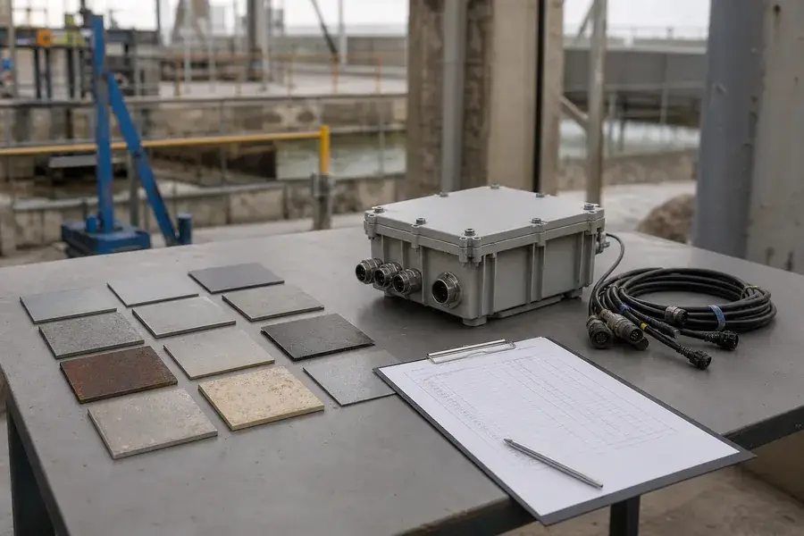
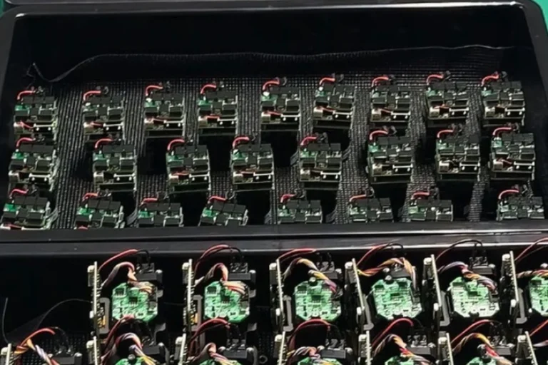
Caption: Conceptual production-planning context only. It is not a Lumexis facility, customer deployment, qualification record, or test result.
FAQ
Is 905 nm the best wavelength for a low-cost rangefinder?
It can align with mature silicon-detector and semiconductor-source options, but the total cost still depends on optics, receiver design, housing, qualification, yield, and expected field conditions. Compare the complete architecture against the required target and measurement method rather than assuming a wavelength determines total cost.
Is a 1.5 µm rangefinder always better for a long path?
No. A long-path result depends on the optical link budget, target, receiver sensitivity, pulse conditions, atmosphere, alignment, and processing. A 1.5 µm architecture may be appropriate for some requirements, but it also introduces different detector and integration considerations that need to be evaluated explicitly.
Does wavelength determine accuracy?
Not by itself. Accuracy also depends on timing method, calibration, receiver signal quality, target behavior, optical alignment, temperature, and processing logic. Treat wavelength as one variable in a measurement chain, then define how accuracy is tested across the intended operating window.
What is the first document to request from a supplier?
Ask for a conditioned performance statement: target, range, atmospheric condition, measurement rate, temperature, supply condition, optical configuration, and test method. For the completed instrument, request the controlled evidence relevant to accessible output and the configuration you intend to ship.
Can the wavelength be changed late in an OEM program?
It can, but it can affect transmitter, receiver, optics, electronics, firmware, mechanics, test method, and supply qualification. Make the change only after revisiting the system matrix and confirming that the performance and verification evidence still applies.
Bring your target, range window, environment, size limit, interface, and planned volume to our engineering team for a grounded wavelength evaluation.