

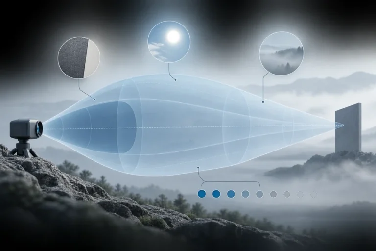

Run the same LiDAR unit across a full day and the point cloud tells a story nobody puts in the datasheet. Clean at dawn. Acceptable mid-morning. Speckled with phantom points by noon.
Nothing about the laser changed. Nothing about the target changed. The sun came up.
A 2023 study in Applied Sciences put numbers on this problem and, more usefully, built hardware that fixes it in real time rather than cleaning it up in software afterward. It is worth reading if you are integrating LiDAR into anything that operates outdoors — the results reframe what a “detection threshold” spec actually means.
Table of Contents
LiDAR background noise is unwanted photocurrent generated when ambient light — mostly sunlight — reaches the receiver alongside the laser return. It raises the noise floor, forcing a higher detection threshold and producing false points in the cloud. Adaptive threshold control based on constant false alarm rate (CFAR) principles suppresses it by adjusting the threshold to measured noise in real time.
What the paper actually studied
The work is titled Adaptive Suppression Method of LiDAR Background Noise Based on Threshold Detection, by Jiang, Zhu, Jiang, Xie, Liu, and Wang, published in Applied Sciences in 2023.
The premise is simple. LiDAR receivers set a detection threshold: any pulse above it counts as a return, anything below is ignored. Set it too low and noise triggers false detections. Set it too high and genuine weak returns from distant or dark targets get missed. Most systems pick one threshold and live with it.
The problem is that the noise the threshold is meant to reject is not constant. It tracks the sun. A threshold tuned at 8 a.m. is wrong at noon, and a threshold tuned at noon throws away range at night.
The authors’ answer is to measure the noise continuously in hardware and move the threshold to match, keeping the false alarm rate constant rather than keeping the threshold constant. That is the CFAR idea, borrowed from radar and applied to a photon-counting front end.
Where the noise comes from
Total noise current at a LiDAR receiver is a sum of contributions: signal shot noise, background optical shot noise, detector dark current, thermal noise, and amplifier input noise.
In a lab, at night, or indoors, the dark current and thermal terms dominate and they are stable. You can design around them once.
Outdoors in daylight, background optical shot noise takes over. Sunlight reaches the detector by several routes — directly, scattered off the atmosphere, and reflected from the target itself — and every one of those photons produces charge carriers in the APD exactly as a signal photon would. The detector cannot tell them apart. What arrives is a fluctuating photocurrent whose statistics scale with received background power.
That is the important asymmetry. Background noise is not a fixed penalty you subtract once. It is a variable that swings by orders of magnitude between midnight and midday, and every parameter downstream that depends on the noise floor swings with it.
Threshold, false alarms, and the trade nobody escapes
Receiver noise is well modeled as Gaussian. That gives a clean relationship between where you put the threshold and how often noise alone crosses it.
The paper expresses the false alarm probability using the error function:
P_f = ½ − ½ · erf( V_T / (√2 · V̄_n) )
where V_T is the threshold voltage and V̄_n is the RMS noise voltage.
The structure of that expression matters more than the algebra. What sets the false alarm rate is not the threshold in volts — it is the ratio of threshold to noise. Raise the threshold and false alarms fall off steeply. But raise the noise while holding the threshold fixed and false alarms climb just as steeply.
This is why a fixed-threshold receiver behaves so differently at different times of day. The engineer set a voltage. Physics is enforcing a ratio.
Which points straight at the fix: hold the ratio constant instead of the voltage. Measure the noise, scale the threshold to it, and the false alarm rate stops moving even as conditions do. That is constant false alarm rate control.
Measuring noise fast enough to matter
Knowing what to do is easy. Doing it inside a pulse detection period is the engineering.
Software post-processing can identify and strip noise points from a cloud, and plenty of systems do exactly that. But it runs after acquisition, on the order of milliseconds, and it can only remove what was recorded — it cannot recover a real return that was lost because the threshold sat too high, and it cannot prevent the receiver from saturating on noise in the first place.
The paper’s approach is entirely in hardware. Two pieces do the work.
A dynamic comparator replaces the conventional continuous comparator in the detection path. Conventional designs count noise crossings. This one uses a pre-amplifier feeding a latched comparator, which lets it measure not just how many noise pulses occur but how long each one lasts. Adding pulse duration to pulse count gives a much better estimate of the actual noise level over a short observation window — which matters, because you have very little time to observe.
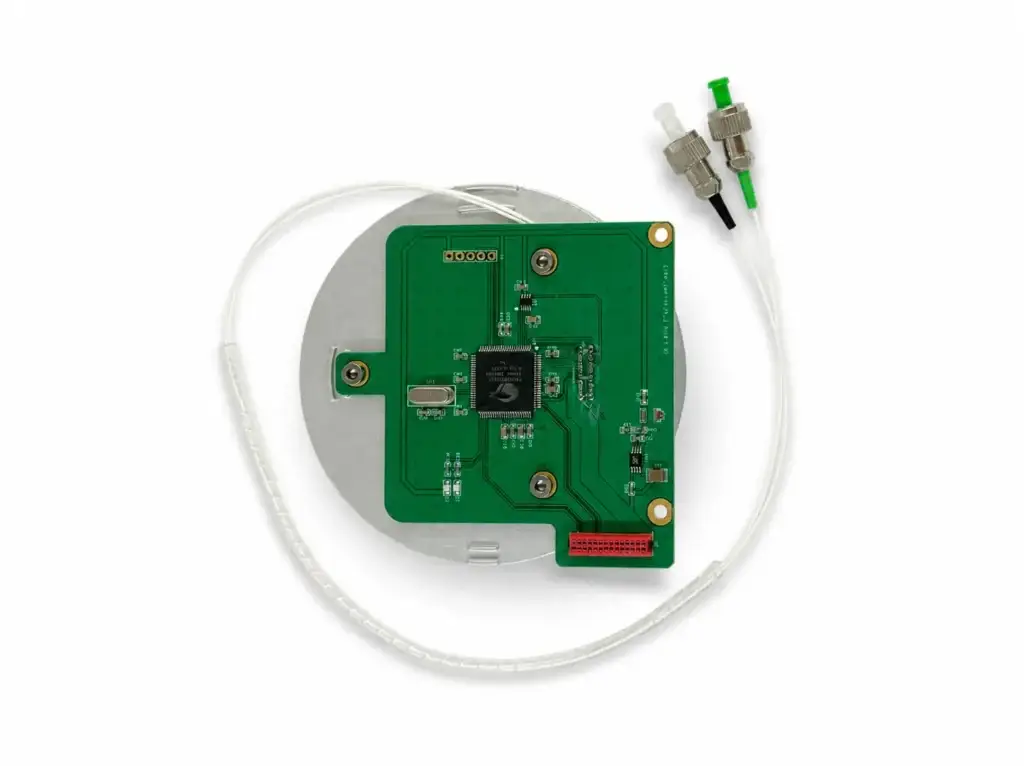
A cascaded threshold adjustment network takes that noise estimate and moves the threshold, with DAC-based correction to keep the step sizes accurate. Because it is a hardware path rather than a processor loop, each adjustment completes within a single pulse detection period.
That timing is the whole point. The system is not reacting to conditions from a millisecond ago. It is tracking them.
The experimental results
The authors tested a 1550 nm system with an APD receiver, a 20 nm optical bandpass filter, a 50 mm receiving aperture, and a field of view of roughly ±35° horizontal by 30° vertical. They compared three operating modes — a traditional fixed threshold, a fast adjustment mode, and the full adaptive mode — by measuring the proportion of noise points in the resulting point cloud at different times of day.
The headline result: at noon, the traditional fixed-threshold mode produced a noise ratio of 0.08%, while the adaptive mode produced 0.012%. That is a reduction of more than 80%.
The pattern across the day is as instructive as the peak number. All three modes look broadly similar early in the morning, when background is low and there is not much to suppress. The gap widens as the sun climbs. By midday — the worst case, and the one that usually defines whether a system is deployable — the fixed-threshold approach is roughly six to seven times noisier than the adaptive one.
Two things worth noting about how to read this. The noon figures come from the abstract and are firm. The intermediate morning values are read from the results figure and should be treated as approximate. And a percentage of noise points is a system-level metric — it depends on scene, range, and reflectivity, so the absolute numbers will not transfer directly to your hardware. The shape of the result will.
What this means if you are integrating LiDAR
Several practical points come out of this that apply well beyond the specific circuit the authors built.
A detection threshold spec without a background condition is incomplete. If a supplier quotes a threshold or a false alarm rate, ask what background level it assumes. The number is meaningless without it, because the physics is governed by the ratio.
Test at noon, not at your convenience. Midday against a bright sky is the worst case for every optical receiver. Acceptance testing scheduled for whenever the range is free will systematically flatter the system.
Hardware and software noise suppression solve different problems. Post-processing removes noise points that were recorded. Adaptive thresholding prevents the threshold from being wrong in the first place, which also protects the weak genuine returns that a too-high fixed threshold would have discarded. They compose well; neither substitutes for the other.
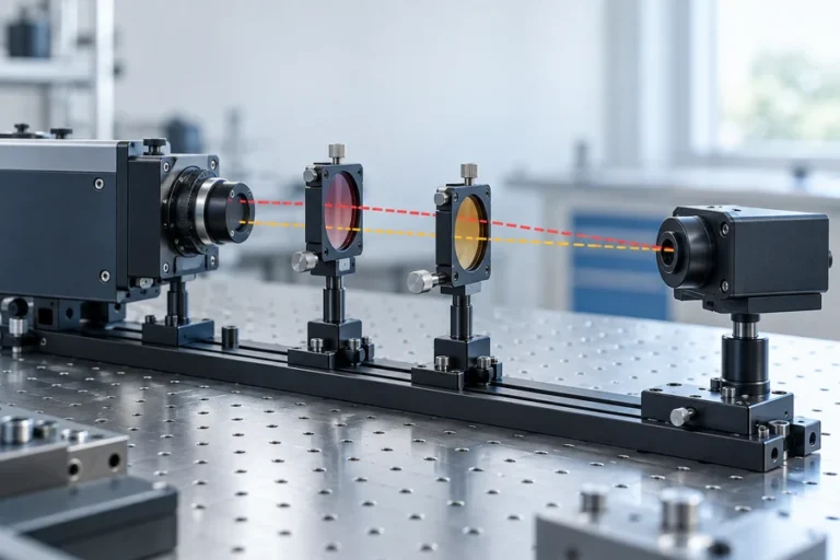
Optical filtering is the first line of defense, and it constrains your laser. The 20 nm bandpass in this experiment rejects most of the solar spectrum before it ever reaches the detector. Narrower is better — but only if the laser’s emission stays inside the passband across the full operating temperature range. A source that drifts off the filter at −30 °C hands you a sensitivity loss that looks exactly like a receiver fault.
That last point is where a study like this connects to source selection. Adaptive threshold control manages the noise you cannot avoid; a stable, tightly specified emission wavelength reduces how much of it reaches the detector at all. Our team characterizes emission wavelength, pulse energy, and trigger-to-emission delay across the full operating window precisely so the receiver’s filter and threshold budget can be designed against real numbers — the same reasoning behind the sources we build for LiDAR and 3D mapping and the broader ranging laser source line.
Wavelength choice shifts the starting point. Solar irradiance is lower around 1.5 µm than near 900 nm, and atmospheric water absorption reduces it further. A 1550 nm system starts with less background to fight before any threshold logic runs — which is part of why the authors built their testbed at that wavelength, and part of why eye-safe LiDAR converges there.
Frequently asked questions
What causes background noise in LiDAR?
Ambient light — overwhelmingly sunlight — reaching the detector alongside the laser return. It arrives directly, scattered by the atmosphere, and reflected from the target. The detector converts those photons to photocurrent indistinguishably from signal photons, raising the noise floor.
What is CFAR in LiDAR detection?
Constant false alarm rate: a control strategy that adjusts the detection threshold in proportion to measured noise, so the false alarm probability stays fixed as conditions change. Borrowed from radar, it replaces a fixed threshold voltage with a fixed threshold-to-noise ratio.
Why does LiDAR perform worse at noon?
Solar background is at its peak, so the receiver’s noise floor is highest. With a fixed threshold, more noise crosses it and false points appear; raising the threshold to compensate discards weak returns from distant or dark targets. Either way, effective performance drops.
Is software denoising enough?
It helps, but it acts after acquisition. It cannot recover real returns already rejected by a threshold set too high, and it does not improve detection sensitivity. Hardware adaptive thresholding addresses the cause; software filtering addresses what got through.
How much improvement is realistic?
The paper reports a point cloud noise ratio of 0.012% in adaptive mode versus 0.08% with a traditional fixed threshold at noon — over 80% reduction. Absolute figures depend on scene, range, and hardware, so treat this as an indication of the achievable magnitude rather than a portable specification.
Does a narrower optical filter make adaptive thresholding unnecessary?
No. A narrow bandpass reduces how much background reaches the detector, but it cannot eliminate in-band solar photons, and narrowing it increases the risk that the laser drifts outside the passband over temperature. The two techniques are complementary.
If you are specifying a LiDAR source
The receiver side of this problem is well documented and, as this paper shows, actively improving. The emitter side sets the boundary conditions: how much energy you may transmit under eye-safety limits, how tightly the receiver’s filter can be specified, and whether the whole budget still closes at the cold end of your operating range.
Send us your background conditions, target reflectivity, and temperature envelope, and our engineers will work through the source options with you — including the wavelength stability data your filter and threshold design will need. You can also review our test and qualification process if you want to see how those numbers are produced.
References
- Jiang, Y.; Zhu, J.; Jiang, C.; Xie, T.; Liu, R.; Wang, Y. — Adaptive Suppression Method of LiDAR Background Noise Based on Threshold Detection. Applied Sciences 2023, 13(6), 3772. Open access, CC BY 4.0.
- Wikipedia — Constant false alarm rate
- International Electrotechnical Commission — IEC 60825-1, Safety of laser products