
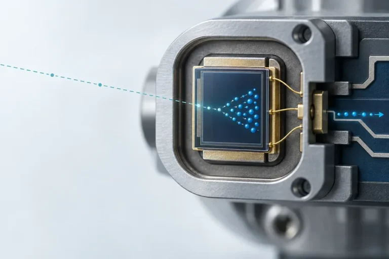



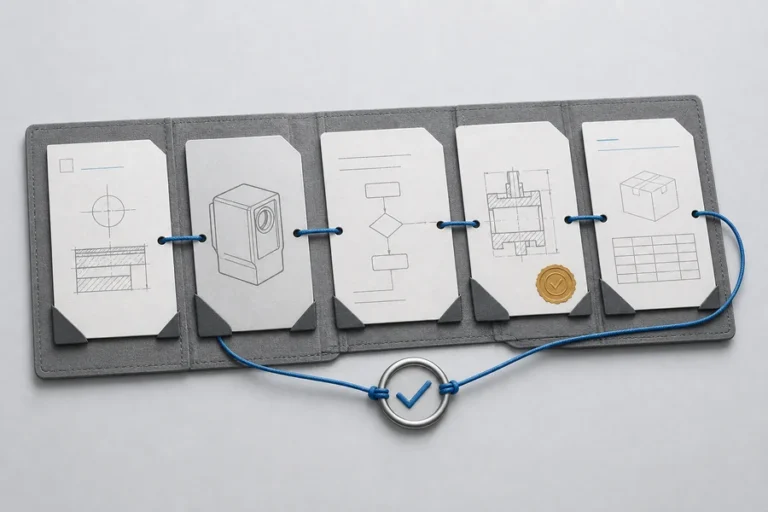
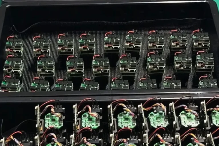





A buyer can ask for a laser rangefinder sensor and receive three very different things: a detector or analog front end, a tiny time-of-flight package, or a complete ranging engine. That naming problem becomes expensive when the quotation looks right but the optical, firmware, mechanical, or validation work still sits with your team.
The useful question is not whether “sensor” or “module” is the better label. It is where the supplier’s tested responsibility ends and your host-system responsibility begins.
A laser rangefinder sensor usually describes a sensing element or compact distance-sensing package, while a laser rangefinder module normally combines the emitter, receiver, optics, processing, and host interface into an OEM subassembly. The terms are not standardized, so buyers should compare the delivered functional boundary, not the product name.
Why “laser rangefinder sensor” is an ambiguous buying term
The word sensor describes a function, not a fixed level of integration. One vendor may use it for a photodetector. Another may mean a reflowable time-of-flight package with an emitter, receiver array, optics, microcontroller, and digital interface. A third may call a housed industrial instrument a sensor.
Manufacturer documentation illustrates the ambiguity. STMicroelectronics describes the VL53L0X as both a time-of-flight ranging sensor and a miniature module that integrates a VCSEL emitter, detector array, microcontroller, optics, and I²C interface. Texas Instruments, by contrast, documents the OPT3101 as an analog front end that still needs external emitters, a photodiode, optics, and board-level integration to become a working distance sensor system.
That difference is larger than terminology. It changes the bill of materials, optical design, firmware scope, calibration process, safety review, test fixtures, and who owns performance when the finished unit misses a target.
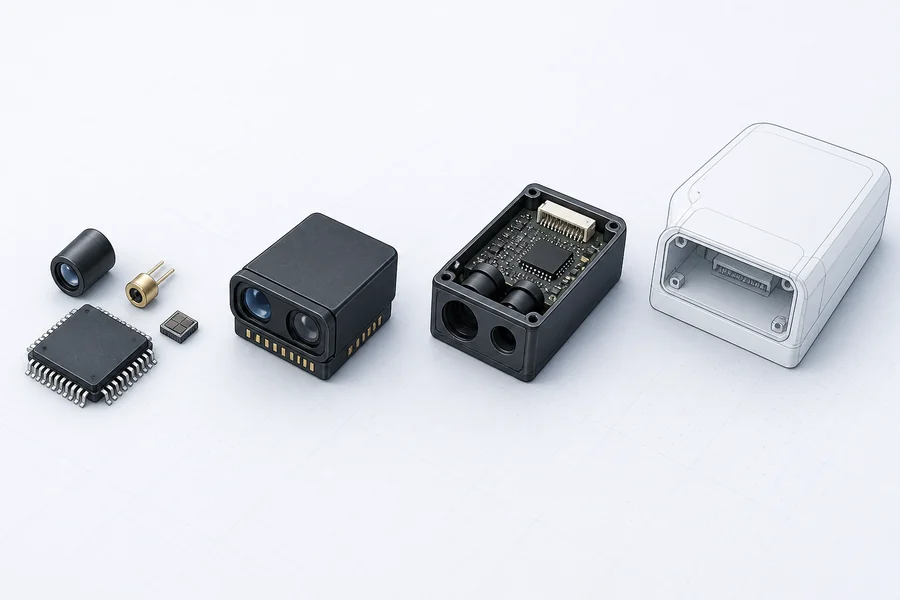
Sensor vs module: compare the delivered boundary
A practical RFQ should identify what is physically delivered and what has already been integrated and verified. The table below gives a useful starting point; a vendor’s actual datasheet and interface-control document remain the authority.
| Buying boundary | Usually included | Usually remains with the OEM | Best fit |
|---|---|---|---|
| Detector or ranging AFE | Detection or timing electronics | Emitter, receiver optics, PCB, algorithms, calibration, enclosure, qualification | Teams building a proprietary sensing architecture |
| Packaged ToF sensor | Highly integrated emitter/receiver package, local processing, digital interface | Cover-window design, host firmware, field of view, thermal/mechanical integration, final-product validation | Compact proximity or embedded short-distance sensing when the specified envelope fits |
| OEM laser rangefinder module | Transmitter, receiver, optics, timing/processing, calibrated ranging output, host interface | Mount, power quality, enclosure/window, host protocol, application validation, completed-product safety assessment | Equipment requiring a discrete ranging engine with lower optical-development burden |
| Finished instrument | Module plus housing, controls, display or industrial interface, declared environmental boundary | Installation, system communication, application acceptance | Standalone measurement or fast deployment |
The word usually matters. A bare board can contain more functional integration than a metal-cased product. Ask for a block diagram and responsibility matrix before comparing prices.
What an OEM laser rangefinder module should remove from your workload
A useful laser rangefinder module is more than a detector on a board. It should accept defined power and control inputs, generate and receive the optical signal, determine a valid range, and return documented data to the host. Its supplier should also define the mechanical datum, apertures, timing, command behavior, error states, and relevant operating conditions.
That boundary can remove substantial optical and signal-chain work, but it does not create a finished system. Your enclosure window can add reflection or crosstalk. A mount can shift boresight. Power noise can corrupt timing or communication. Target size, angle, reflectance, ambient light, atmosphere, and motion can change the return margin. Our guide to how a laser rangefinder works follows these dependencies through the complete measurement chain.
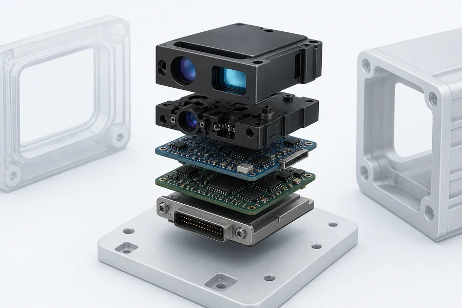
A module does not transfer every system responsibility
The host manufacturer still owns the final optical window, power supply, cable and grounding, heat path, alignment, command timing, environmental protection, and application acceptance test.
Laser safety also belongs to the final configuration. A wavelength label alone does not establish a safety class, and a module-level assessment does not automatically cover a host product with different optics or operating modes. Keep the safety boundary explicit in both the interface documentation and the validation plan.
When a sensor-level design is the better choice
Choosing a sensor or AFE can be rational when the ranging architecture itself is part of your product advantage. Your team may need a custom field of view, unusual packaging, a specific emitter, proprietary processing, or board-level control.
The trade is engineering ownership. TI’s time-of-flight design guide shows that an AFE-based implementation can involve emitter and photodiode selection, optical isolation, cover-glass design, PCB partitioning, calibration, ambient-light behavior, and system-level testing. A low component price is not the same as a low developed cost.
Use a sensor-level route when you have the optical, analog, firmware, manufacturing, and qualification resources to own those decisions through production. It is a poor shortcut without a plan for optical calibration or production screening.
When a laser rangefinder module is the better choice
A module is usually stronger when ranging is an important subsystem but not the OEM’s core sensing architecture. It can shorten prototyping, provided its verified envelope matches the real target and environment.
Start with the required measurement, not the preferred wavelength or a headline maximum range. Define the minimum and maximum distance, target size and surface, field of view, ambient light, atmosphere, update behavior, valid-reading criteria, mechanical envelope, power budget, host interface, operating temperature, and production quantity. The laser rangefinder module selection guide explains how to compare candidates under common conditions.
Then check whether the module documentation answers four questions:
- What is inside the boundary? Confirm the transmitter, receiver, optics, processing, firmware, and calibration scope.
- What crosses the boundary? Record power rails, logic levels, connector, commands, timing, data format, error codes, and update behavior.
- What conditions define performance? Require target, distance, ambient, temperature, repetition, acceptance method, and test setup where relevant.
- What changes at production scale? Ask about configuration control, traceability, screening, change notification, and sample-to-production equivalence.
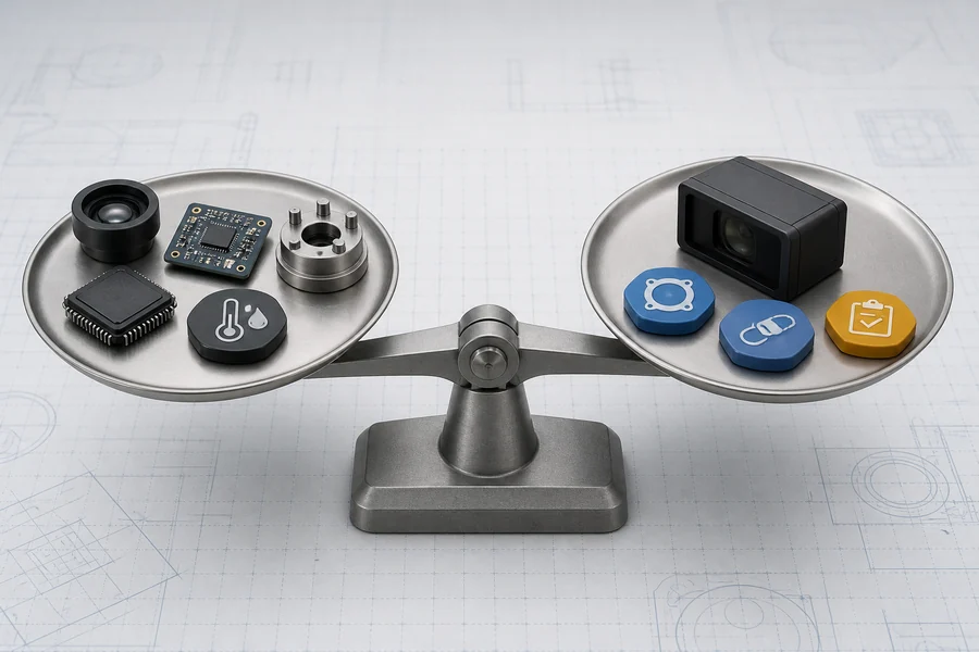
The seven checks to put in an RFQ
Product labels disappear once a program reaches engineering review. These seven checks make quotations comparable:
- Functional boundary: a supplier block diagram showing included and external functions.
- Optical boundary: transmitter and receiver apertures, field of view, alignment datum, window constraints, and stray-light controls.
- Electrical boundary: input range, current behavior, logic levels, connector, grounding, protection, and noise limits.
- Data boundary: commands, units, valid/invalid flags, latency, measurement rate, timeouts, and reset behavior.
- Mechanical and thermal boundary: envelope, mounting datum, tolerance, mass, heat path, and installation constraints.
- Validation boundary: target, environment, sample size, method, acceptance criteria, and completed-host retest plan.
- Production boundary: configuration ID, change control, traceability, screening, service support, and lifecycle expectations.
This information is more valuable than a generic “plug-and-play” claim. It tells your mechanical, electronics, firmware, quality, and purchasing teams exactly what they are accepting.
How Lumexis supports the module boundary
Lumexis develops laser ranging modules and sources for civil measurement, industrial inspection, and scientific instruments. Our applications engineers can review the target, optical envelope, interface, mounting, operating environment, validation method, and production requirement before a configuration is selected.
The Wuxi engineering and commercial team is supported by a 14,000-square-meter manufacturing base in Taizhou. In-house optical and optomechanical design, electronics and firmware, weak-signal algorithms, controlled assembly, burn-in screening, temperature cycling, metrology, and final test help keep the module boundary tied to repeatable production evidence. Engineering services also support suitable custom and private-label programs; standard products can ship within three days, while custom timing is confirmed against the project scope.
Frequently asked questions
Is a laser rangefinder sensor the same as a laser rangefinder module?
Not reliably. Some suppliers use the terms interchangeably, while others use sensor for a detector, AFE, or miniature ToF package and module for a complete ranging subassembly. Compare the included emitter, receiver, optics, processing, firmware, calibration, and interface rather than relying on the label.
Is a ToF sensor always for short range?
No. Time of flight is a measurement principle, not a fixed distance class. Integrated proximity sensors, OEM rangefinder modules, and larger systems can all use ToF architectures. Their useful distance depends on the emitter, receiver, optics, field of view, target, ambient conditions, processing, and safety constraints.
Does an OEM module need calibration in the final product?
The module may be calibrated as supplied, but the installed system still needs validation. A cover window, mount, power supply, cable, temperature path, or host timing can change alignment, crosstalk, communication, or acceptance behavior. Define which adjustments are factory-controlled and which checks must be repeated after installation.
Which option gives the lowest total cost?
There is no universal winner. A sensor-level design may reduce component cost but adds optical, electronics, firmware, fixture, calibration, qualification, and sustaining work. A module costs more as a subassembly but can reduce development time and interface count. Compare developed cost, production yield, field risk, and lifecycle support.
What should I send a module supplier first?
Send the target and distance window, ambient and atmospheric conditions, field of view, update behavior, valid-reading criteria, mechanical envelope, power budget, host interface, operating temperature, expected quantity, and validation method. Those inputs let an applications engineer identify gaps before recommending a standard or custom configuration.
References
- STMicroelectronics, VL53L0X Time-of-Flight Ranging Sensor, product overview and integration features.
- Texas Instruments, Introduction to Time-of-Flight Long Range Proximity and Distance Sensor System Design, Rev. B, August 2019.
- IEC, IEC 60825-1: Safety of Laser Products, classification and requirements context.
If you are choosing between a sensor-level design and an OEM module, send Lumexis your target, distance window, envelope, interface, environment, quantity, and acceptance method. Our applications engineers can identify the correct integration boundary, recommend a standard product where it fits, or review a custom configuration and validation plan.