








Choosing among laser rangefinder modules gets difficult when a datasheet reduces the decision to maximum distance and accuracy. Those numbers matter, but they do not describe target reflectance, ambient light, host interfaces, heat flow, or how repeatability was checked. The result is a module that looks suitable on paper and creates avoidable integration work later.
For OEM teams, the useful question is not simply which module has the largest headline figure. It is which measurement architecture, optical arrangement, and qualification evidence fit the real measurement task.
The main types of laser rangefinder modules are pulsed time-of-flight, phase-shift, and triangulation designs. Pulsed time-of-flight measures a returned light pulse directly; phase-shift designs infer travel time from modulation; triangulation derives distance from geometric displacement. The right choice depends on working distance, target behavior, measurement rate, required uncertainty, packaging, and the evidence available at the intended operating point.
Start with the measurement problem, not the module label
“Laser rangefinder module” describes an integration form factor, not one universal measurement method. A compact module may contain an emitter, transmit and receive optics, a photodetector, timing or demodulation electronics, firmware, and a host interface. The architecture inside determines what the system must control and validate.
Before comparing options, write down the target material and reflectance, distance envelope, field of view, measurement cadence, allowed housing volume, electrical interface, operating temperature, and the acceptance test you will use. A painted wall, a retroreflective marker, a dark coated surface, and a slanted metal panel can return very different signals at the same distance. The module selection must be tied to that reality.
Pulsed time-of-flight modules
Pulsed time-of-flight modules emit a short optical pulse and measure the elapsed time before reflected light reaches the receiver. In the simplest range equation, distance equals one-half the speed of light multiplied by round-trip time. In production hardware, the result also depends on pulse shape, detector response, thresholding or timing extraction, optical alignment, and signal processing.
This approach is a natural fit when the application needs a single, directed distance measurement across a broad working-distance window. The architecture separates the outbound event from the detected return, so teams can reason explicitly about transmitter energy, receiver sensitivity, target reflectance, atmospheric loss, and timing jitter. It also makes test conditions especially important: a reported range without a stated target, alignment, temperature, and ambient-light condition is incomplete engineering information.
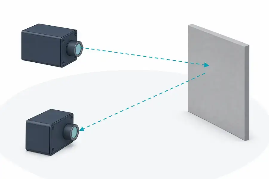
Typical pulsed time-of-flight concept. The dashed paths are conceptual invisible-light paths and do not depict a specific Lumexis module architecture.
What to verify for pulsed designs
Ask how the supplier defines a return, how false returns are handled, and what target conditions were used. Review the optical separation between transmit and receive paths, the receiver recovery behavior after a transmit event, the electrical timing reference, and the host command sequence. If the module is being integrated behind a protective window, validate the complete optical stack rather than assuming a bare-module result will transfer unchanged.
For a system intended for civil infrastructure inspection, surveying instruments, or scientific measurement, we would also define a test matrix before sampling. It should include the intended target set, off-axis geometry, bright-background conditions, and the temperature range that matters to the finished instrument. That makes sample comparison repeatable instead of anecdotal.
Phase-shift rangefinder modules
Phase-shift designs transmit an intensity-modulated optical signal and compare the received modulation with the reference signal. The measured phase is related to travel time, so the system can resolve distance without detecting a single pulse edge in the same way as a pulsed design. Multiple modulation frequencies can help address phase ambiguity, but the implementation and the resulting measurement behavior are application-specific.
These modules are often considered where a controlled distance interval and fine repeatability are central. Their suitability still depends on the measurement scene. Surface properties, ambient light, optical cross-talk, modulation design, demodulation electronics, and calibration strategy all influence the practical result. A buyer should request the operating range of the reported measurement result and the method used to control ambiguity.
Triangulation modules and sensors
Triangulation measures geometry rather than round-trip flight time. A projected spot is viewed by a detector at a known baseline; as target distance changes, the spot position changes in the receiver field. This can be effective for short working distances where displacement resolution is more important than a broad range envelope.
Triangulation is frequently grouped with laser distance measurement, but it asks different questions of the mechanical design. Baseline stability, lens geometry, target angle, surface texture, and spot imaging can dominate performance. It is not automatically a substitute for a pulsed rangefinder module in a long-working-distance instrument. Treat it as a distinct architecture with its own integration and calibration plan.
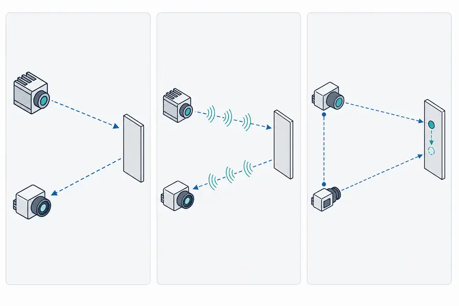
Conceptual comparison only. The dashed paths encode invisible optical routes; this graphic does not provide product performance data or a specific product design.
Types of laser rangefinder modules: a practical comparison
The table below is a scoping tool, not a substitute for a product-specific evaluation.
| Architecture | Distance is derived from | Integration focus | Evaluation questions |
|---|---|---|---|
| Pulsed time-of-flight | Round-trip pulse timing | Receiver sensitivity, timing extraction, target return | What target and ambient conditions support the requirement? |
| Phase-shift | Phase difference of a modulated return | Modulation, ambiguity handling, calibration | Over what interval and surface set is the result demonstrated? |
| Triangulation | Image or spot-position geometry | Baseline, optics, target angle and texture | How stable is geometry across mounting and temperature? |
Wavelength should be selected as part of a system-level optical and detector decision, not as a standalone shortcut. It affects source and detector choices, optical coatings, background response, and the available implementation path. Any safety classification must be established for the completed product and its use conditions; it should not be inferred from wavelength alone.
A practical OEM selection workflow
First, separate “must measure” from “nice to have.” Define the target, smallest and largest working distances, acceptance uncertainty, update behavior, host power budget, and interface. Then select the measurement principle that naturally fits those constraints rather than trying to compensate for an architectural mismatch in firmware.
Second, review the module as an assembly. Check the mechanical datum surfaces, aperture clearance, connector retention, cable routing, electrical grounding, thermal path, and any window or bezel in the host enclosure. A clean optical path on the bench can become a different measurement system after the module is mounted in a product.
Third, make qualification evidence part of the purchase decision. Useful evidence includes defined incoming inspection, optical alignment controls, aging or burn-in screening, temperature cycling, final functional testing, and traceability through production changes. These practices do not replace application validation, but they reduce the chance that a well-performing sample hides an unstable production process.
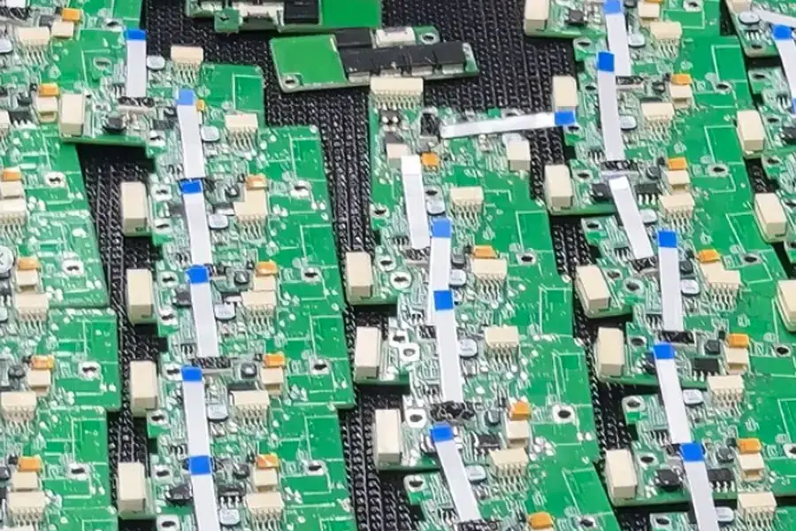
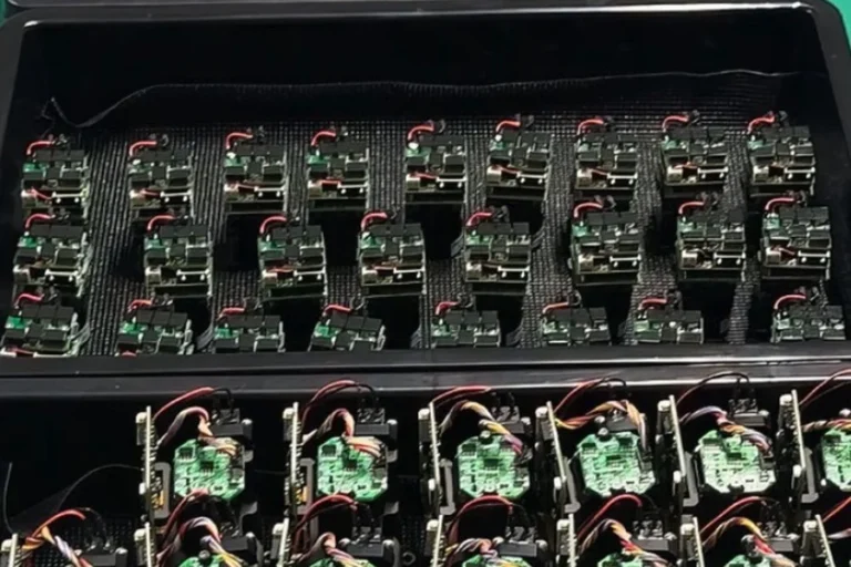
Representative module assembly boards used as production context. The image supports process discussion only and does not state a product specification or qualification result.
How Lumexis approaches rangefinder module selection
At Lumexis, we design and manufacture laser rangefinder modules for civil measurement, industrial inspection, and scientific instruments. Our team starts with the measurement conditions and integration envelope, then works through optical, electronic, mechanical, and test trade-offs with the system designer.
The production flow matters because module behavior is created by more than a circuit board. Incoming inspection, chip testing, die bonding, fiber coupling and alignment where applicable, sealing, aging screening, and final performance testing each provide a control point. You can see the broader engineering context in our technology capabilities and explore relevant laser ranging solutions.
For a new program, bring your target set, distance envelope, mounting model, interface requirements, and environmental conditions to the first review. That gives us a common basis for a realistic evaluation plan and an integration path that supports reliable supply.
FAQ
Which type of laser rangefinder module is best for long working distances?
There is no universal distance threshold that selects a module by itself. Pulsed time-of-flight is commonly used where direct round-trip timing and a broad working-distance envelope are useful. The viable result still depends on target reflectance, optics, atmospheric conditions, receiver sensitivity, and the test method. Evaluate with representative targets rather than a headline figure alone.
Are phase-shift and time-of-flight the same thing?
Both are related to light travel time, but they obtain the measurement differently. A pulsed time-of-flight design measures a returned pulse event directly. A phase-shift design estimates travel time from the phase relationship between transmitted modulation and the received signal. Their electronics, ambiguity handling, and validation requirements differ.
Can a triangulation sensor replace a laser rangefinder module?
It can be appropriate for a short-range displacement problem, but it is not a drop-in replacement for every ranging task. Triangulation depends on optical baseline and spot imaging, while a time-of-flight module depends on detecting a reflected return. Compare the required working distance, target variation, mechanical envelope, and calibration burden before choosing.
What should an OEM ask for during module evaluation?
Ask for the exact conditions behind each claimed result: target type, distance, target angle, ambient light, temperature, supply conditions, update behavior, and measurement definition. Also review the host interface, mounting data, thermal requirements, change-control process, and the acceptance test proposed for samples and production units.
Does wavelength alone determine whether a rangefinder is safe to use?
No. Safety classification depends on the completed product, its emission characteristics, optics, operating modes, and use conditions. Evaluate it at the system level with the appropriate documented evidence rather than relying on wavelength as a shortcut.
If you are comparing types of laser rangefinder modules for an OEM program, contact our engineering team with your target conditions, envelope, interface, and validation needs.
References
- RP Photonics, “Laser Rangefinders” — measurement-principle overview.
- Fraunhofer IPM, “Optical Distance Measurement” — time-of-flight and phase-shift context.
- NIST, “Laser Comb System Maps 3D Surfaces Remotely” — round-trip laser time-of-flight context.