









Solid-state lasers appear simple on a block diagram, yet specifying one for a real instrument is rarely straightforward. A familiar wavelength or a high peak-power number may look right while the thermal design, pulse behavior, beam definition, or qualification method makes the source unsuitable.
This guide explains the physics without losing sight of those engineering details. It covers the main gain media, pumping and pulse architectures, performance trade-offs, and the questions an OEM team should settle before committing to a design.
Solid-state lasers use a crystal or glass gain medium containing active ions. Optical pumping excites those ions, a resonator provides feedback, and stimulated emission produces a controlled beam. The host and dopant set the wavelength and energy-storage behavior, while the pump, cavity, thermal path, and pulse method determine usable system performance.
Definition and Scope
A solid-state laser uses a transparent solid as its active gain medium, usually a crystal or glass host doped with rare-earth or transition-metal ions. The dopant provides the useful electronic transitions. The host holds those ions in a stable physical structure and strongly influences thermal conductivity, mechanical behavior, spectral bandwidth, and manufacturability.
In conventional industry usage, “solid-state laser” usually means a bulk crystal or glass laser. Semiconductor lasers are also solids, and optical fiber can contain a solid doped-glass core, but diode lasers and fiber lasers are normally treated as separate technology families because their carrier physics, waveguiding, packaging, and scaling methods differ from bulk devices [1].
That distinction matters in sourcing. A diode-pumped solid-state laser, or DPSS laser, uses a semiconductor laser as the pump, but the resonator output is generated by the separate crystal or glass gain medium.
How Solid-State Lasers Work
Every solid-state laser needs three functions: energy input, optical gain, and feedback. A lamp or laser diode supplies pump light. The gain medium absorbs part of that light and stores energy in excited ions. Mirrors around the medium form a resonator, with one mirror partially transmitting the useful output.
Once pumping produces sufficient population inversion, a photon at the laser transition can stimulate an excited ion to emit another photon with the same frequency, phase relationship, and direction. Repeated passes through the resonator amplify selected optical modes until gain balances cavity loss and output coupling.
The emitted photon energy follows:
E = hc / λHere, E is photon energy, h is Planck’s constant, c is the speed of light, and λ is wavelength. The equation does not tell you the output wavelength by itself; the dopant-host energy levels and resonator design determine which supported transition oscillates.
Pumping: Flashlamps Versus Laser Diodes
Flashlamps deliver broad-spectrum pump light and can energize relatively large gain volumes, but much of their spectrum may fall outside the useful absorption bands. Laser diodes can be selected to better match an absorption band. Their compact size and controllable drive also support smaller, more efficient packages.
The match is not just a wavelength entry on a drawing. Pump spectral width and center wavelength change with current and temperature, while the gain medium has a finite absorption spectrum. An engineering review should therefore compare the pump spectrum across the operating window, not only at room temperature.
Pump geometry also changes performance. End pumping can provide strong overlap between pump and resonator modes. Side pumping can distribute energy through a larger volume. Neither is universally better; the decision depends on desired mode size, stored energy, beam quality, package envelope, and heat-removal path.
Continuous-Wave and Pulsed Operation
A continuous-wave (CW) laser produces a sustained output under steady conditions. Pulsed designs release energy over defined time intervals. Do not compare them using output power alone.
For a pulse train:
Average power: P_avg = E_pulse × f_rep
Approximate peak power: P_peak ≈ E_pulse / τ
E_pulse is pulse energy, f_rep is repetition rate, and τ is pulse duration under a stated width convention. The peak-power expression is an estimate unless pulse shape is included. Two products with the same average power can impose very different optical-damage, detector, and thermal requirements.
Q-switching prevents oscillation while pump energy accumulates, then rapidly lowers cavity loss to release a short, energetic pulse. Active systems use a controlled intracavity modulator; passive designs often use a saturable absorber. Mode locking serves a different purpose: it fixes the phase relationship among longitudinal modes to generate much shorter pulse trains. Treat “pulsed” as a category, not a complete specification [2].
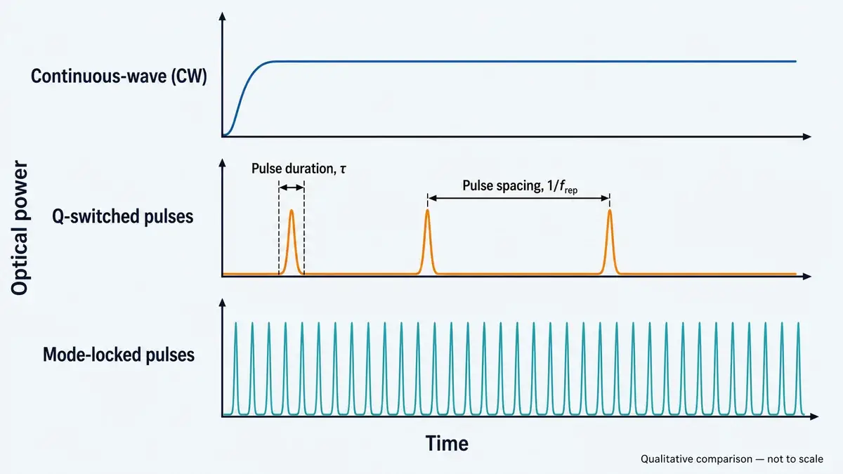
CW output is continuous, while Q-switched and mode-locked sources produce pulse trains on very different time scales. Qualitative comparison; not to scale.
Common Gain Media for Bulk Lasers
The active ion and host work as a pair. Swapping the host while keeping the dopant can change absorption, emission cross-section, upper-state lifetime, bandwidth, thermal conductivity, and polarization behavior. That is why a material name should never stand in for a complete source specification.
| Gain medium | Typical output region | Engineering character | Common fit within approved applications |
|---|---|---|---|
| Nd:YAG | Near 1064 nm | Mature crystal platform with useful thermal and mechanical properties; supports CW and pulsed designs | Industrial pumping and scientific instrumentation |
| Nd:YVO4 | Near 1064 nm | High gain can support compact, low-threshold oscillators; thermal behavior requires careful design | Scientific instruments and compact optical sources |
| Yb:YAG | Near 1 µm | Small pump-to-laser energy difference can reduce quantum-defect heating; often used in power-scalable architectures | Industrial pumping and research sources |
| Er:glass | Around the 1.5 µm region | Glass host supports compact source formats; thermal and pulse behavior depend on composition and package | Precision ranging, LiDAR, and scientific instrumentation |
| Ti:sapphire | Broadly tunable in the near infrared | Wide gain bandwidth supports tunable and ultrashort-pulse research systems | Scientific instrumentation |
| Ruby | Around 694 nm | Historically important three-level laser with a relatively high pumping threshold | Research and laser-physics education |
These wavelength regions are orientation values, not procurement limits. Exact output depends on material composition, transition, cavity optics, temperature, and any nonlinear frequency conversion. A frequency-doubled source, for example, should be reviewed as a full architecture rather than described only by its visible output wavelength.
Glass and crystalline hosts also create different trade-offs. Glass can offer compositional flexibility, broad spectra, and adaptable shapes, while many crystalline hosts provide stronger thermal conductivity. Broad bandwidth can be valuable for tunability or short pulses, but it may come with lower emission cross-sections or weaker thermal properties. Gain-medium selection is an optimization problem, not a ranking [3].
Why Erbium-Glass Lasers Deserve Separate Attention
An Er:glass laser is a bulk solid-state laser whose erbium-containing glass provides the gain. It is not the same architecture as an erbium-doped fiber laser, even if their spectral regions overlap.
For precision ranging and scientific instruments, source evaluation should connect pulse energy, pulse width, repetition rate, divergence, beam alignment, temperature behavior, and receiver response. A wavelength alone does not establish system range or laser safety. The completed product must be assessed under its actual accessible-emission conditions using the applicable standard and measurement setup [4].
LUMEXIS develops erbium-glass laser sources as one of our four focused technology platforms. Our broader laser technology approach connects optical design with packaging, electronics, firmware, thermal management, and test-method development rather than treating the source as an isolated optical part.
Bulk Laser Architectures and Their Trade-Offs
Bulk gain media can be formed as rods, slabs, disks, or compact microchip structures. Geometry controls the pump distribution, resonator mode, surface-to-volume ratio, stress pattern, cooling direction, and practical package size.
A rod is familiar and mechanically straightforward, but radial temperature gradients can produce thermal lensing and stress. Slabs spread heat and can support a wider optical path, though the resonator and pump arrangement become more involved. Thin-disk designs remove heat mainly through a short axial direction, which can help power scaling. Microchip lasers shorten and simplify the cavity for compact pulsed sources, but tight tolerances and small optical areas raise coating, alignment, and damage considerations.
The best architecture is the one that remains stable at the required operating point. A laboratory demonstration at nominal temperature does not prove that the resonator will preserve output energy, pointing, mode size, and pulse timing after warm-up or across a specified environmental range.
Advantages and Limitations of Bulk Laser Sources
Solid-state platforms can combine compact packaging, broad wavelength options, strong energy storage, and precise temporal control. Diode pumping can improve electrical and thermal practicality compared with broadband lamp pumping. Bulk media can also provide larger optical mode areas than many guided-wave devices, which is useful when pulse energy matters.
The limitations are equally important. Absorbed pump power that does not leave as useful laser output becomes heat. Temperature gradients change refractive index, create stress, and can deform optical surfaces. The result may be thermal lensing, depolarization, beam degradation, resonator instability, wavelength drift, or reduced component life [3].
Free-space cavities also depend on alignment. Mechanical movement, adhesive behavior, coating contamination, solder stress, and thermal expansion can shift performance even when every individual component passed incoming inspection. Reliability must be designed into the optical, mechanical, electrical, and thermal stack together.
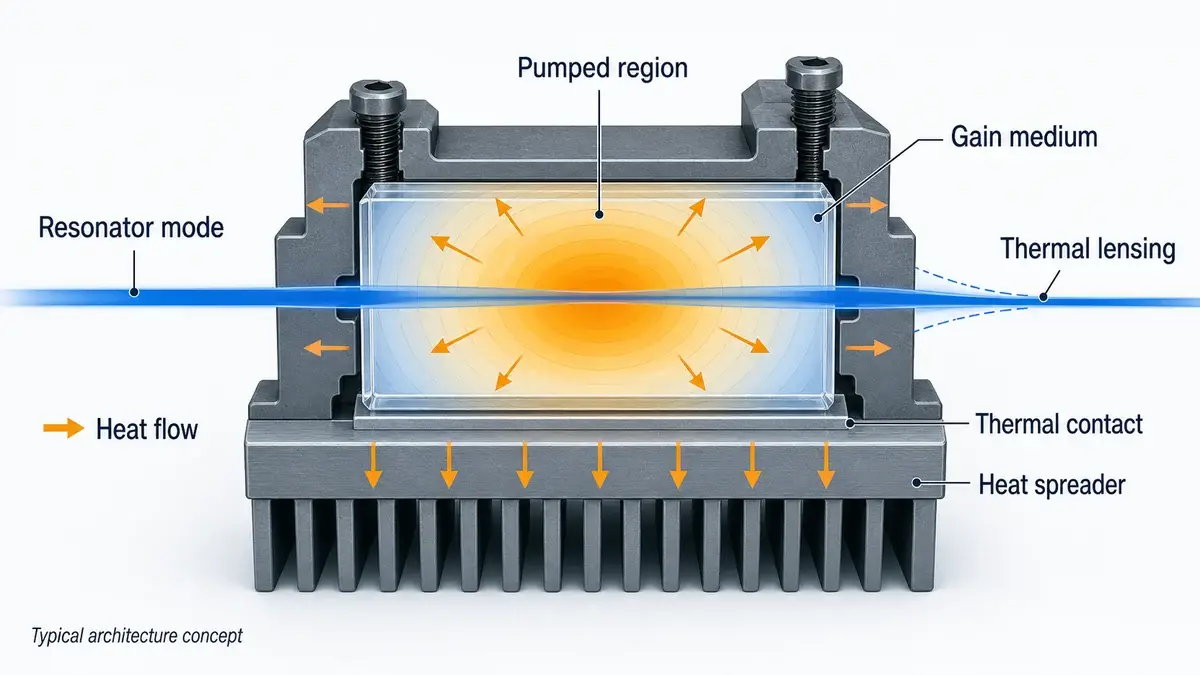
A qualitative bulk-laser cutaway showing how heat can travel from the pumped region into the mount while a temperature gradient changes the resonator mode. Typical architecture concept.
How to Choose a Solid-State Laser
Start with the optical task, not a favorite gain medium. Define what the source must produce at the system interface and under which conditions. Wavelength is only the first gate.
1. Specify the Output in Complete Sets
For CW operation, state optical power with operating temperature, drive condition, warm-up behavior, beam diameter, divergence or M², polarization, and stability interval. For pulsed operation, keep pulse energy, duration, repetition rate, average power, timing jitter, and pulse-to-pulse stability together.
Ask how each number was measured. “Beam diameter” may refer to a 1/e² width, FWHM, or another definition. Divergence may be a full or half angle. Pulse width may be FWHM while a peak-power calculation assumes a rectangular pulse. Those mismatches can propagate into incorrect optics, receiver saturation, or thermal budgets.
2. Model the Interfaces
The source interacts with drive electronics, mounting surfaces, heat sinks, optics, detectors, firmware, and the enclosure. Document allowed current and voltage behavior, trigger levels, grounding, connector pinout, mounting flatness, thermal resistance, optical-axis position, and back-reflection exposure.
For a diode-pumped design, pump quality deserves the same discipline. Fiber core size, numerical aperture, connector or splice format, coupling efficiency, wavelength-temperature behavior, and return-light management all influence delivered pump power and lifetime. Our fiber-coupled laser solutions are developed around controlled beam delivery and integration rather than emitter power in isolation.
3. Test the Real Operating Window
Room-temperature typical values are not a qualification plan. Request data at the relevant temperature, duty cycle, repetition rate, mounting condition, and warm-up state. If the instrument operates dynamically, include transitions rather than measuring only after equilibrium.
Thermal cycling can expose alignment shifts and interconnect stress. Burn-in or aging screening can help identify early-life failures. Hermetic sealing may be relevant when moisture or contamination could affect coatings, surfaces, or bonds, but the package design and leak-test evidence should support the claim.
4. Review Laser Safety at Product Level
Never infer a safety class from wavelength alone. Classification depends on accessible emission, pulse characteristics, exposure duration, aperture, beam geometry, scanning behavior, and product construction. IEC 60825-1 covers classification and requirements for laser products across 180 nm to 1 mm; the final system manufacturer must evaluate the completed product under the applicable rules [4].
5. Compare Lifecycle Risk, Not Unit Price Alone
A lower purchase price can be erased by thermal redesign, field drift, inconsistent lots, long replacement lead times, or undocumented process changes. Ask what is controlled at incoming inspection, assembly, alignment, sealing, screening, and final test. Traceability and change control are commercial requirements as much as quality requirements.
Browse our current laser source and module portfolio to see how wavelength, source architecture, and package format are separated at product level.
What to Look for in a Laser Source Supplier
A credible supplier should translate a requested headline specification into a testable operating condition. If you request pulse energy, the response should also address repetition rate, pulse-width definition, temperature, drive point, sampling method, and acceptable variation. If you request beam quality, the measurement plane and method should be clear.
At LUMEXIS, our team connects optical and optomechanical design with semiconductor laser packaging, fiber coupling, electronics, firmware, weak-signal ranging algorithms, and thermal design. Production steps can include incoming inspection, chip testing, die bonding, soldering, alignment, hermetic sealing, aging screening, and final performance testing. The exact process depends on the source and package.
For a qualification discussion, ask for evidence relevant to your use case: temperature-dependent data, burn-in conditions, optical-axis tolerance, pulse measurement setup, lot traceability, and acceptance criteria. A generic certificate or a room-temperature graph cannot replace those details.
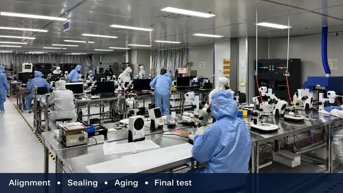
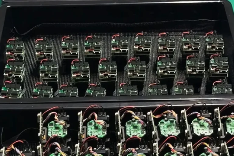
Controlled assembly, alignment, sealing, aging, and final testing help translate an optical design into repeatable production hardware.
Frequently Asked Questions
What is the main difference between a solid-state laser and a diode laser?
A conventional solid-state laser generates its output in a doped crystal or glass that is optically pumped. A diode laser generates light through electron-hole recombination in a semiconductor junction. A DPSS laser contains both: the diode supplies pump light, and the separate bulk gain medium produces the resonator output.
Is a fiber laser a solid-state laser?
Physically, its doped-glass fiber is solid, so a fiber laser belongs to the wider solid-state family. In commercial and engineering usage, fiber lasers are usually treated separately from bulk solid-state lasers because the fiber waveguide controls the optical mode, pump coupling, thermal behavior, nonlinear effects, and package architecture.
What are the most common solid-state laser materials?
Common media include Nd:YAG, Nd:YVO4, Yb:YAG, Er:glass, Ti:sapphire, and ruby. The label combines an active ion with a host, and both matter. Compare absorption, emission wavelength, bandwidth, upper-state lifetime, thermal conductivity, mechanical properties, and the required CW or pulsed regime before choosing.
What is a Q-switched solid-state laser?
A Q-switched laser stores pump energy in its gain medium while cavity loss is kept high. When the loss is lowered, that stored energy is released as a short, high-peak-power pulse. The specification still needs pulse energy, width, repetition rate, average power, stability, and operating conditions; “Q-switched” alone is incomplete.
Why is thermal management critical in solid-state lasers?
Not all absorbed pump energy becomes laser output. The remaining heat creates temperature gradients that can change refractive index, induce mechanical stress, and deform surfaces. These effects may alter beam quality, alignment, efficiency, pulse behavior, and lifetime, so the gain medium, mount, cooling path, and resonator must be designed together.
Are 1.5 µm solid-state lasers automatically eye-safe?
No. Wavelength influences how radiation interacts with the eye, but it does not determine the safety class by itself. Accessible emission, pulse energy and duration, repetition pattern, aperture, divergence, exposure conditions, and product safeguards all matter. Classify the completed laser product using the applicable standard and verified measurements.
If you are selecting a bulk solid-state source, an erbium-glass laser, or its pump architecture, bring us the operating window and interface constraints, not just a target wavelength. Talk to our engineers about a source and qualification path that fits the instrument.
References
1. N. Hodgson and H. Weber, Solid-State Laser Engineering, CREOL, University of Central Florida: Solid-State Lasers. 2. R. Paschotta, RP Photonics Encyclopedia: Q-Switching. 3. R. Paschotta, RP Photonics Encyclopedia: Laser Gain Media and Thermal Lensing. 4. International Electrotechnical Commission, IEC 60825-1:2014 — Safety of Laser Products, Part 1.