

تبدو ليزرات الحالة الصلبة بسيطة في مخطط الكتلة، ومع ذلك فإن تحديد مواصفات واحدة لأداة حقيقية نادرًا ما يكون مباشرًا. قد يبدو طول موجي مألوف أو رقم قدرة ذروة عالية مناسبًا بينما يجعل التصميم الحراري، أو سلوك النبضة، أو تعريف الحزمة، أو طريقة التأهيل المصدر غير مناسب.
يشرح هذا الدليل الفيزياء دون إغفال تلك التفاصيل الهندسية. ويغطي وسائط الكسب الرئيسية، وهياكل الضخ والنبض، والمفاضلات في الأداء، والأسئلة التي يجب أن يحسمها فريق OEM قبل الالتزام بتصميم.
تستخدم ليزرات الحالة الصلبة وسط كسب بلوري أو زجاجي يحتوي على أيونات نشطة. الضخ البصري يثير تلك الأيونات، ويوفر الرنان التغذية الراجعة، وينتج الانبعاث المحفز حزمة محكومة. تحدد المادة المضيفة والمادة المشوبة الطول الموجي وسلوك تخزين الطاقة، بينما تحدد المضخة والتجويف والمسار الحراري وطريقة النبض أداء النظام القابل للاستخدام.
التعريف والنطاق
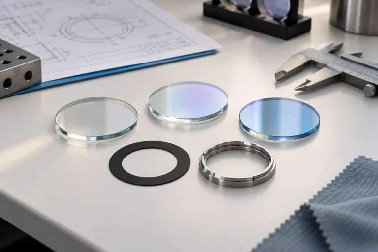
يستخدم ليزر الحالة الصلبة مادة صلبة شفافة كوسط كسب نشط، وعادة ما يكون مضيفًا بلوريًا أو زجاجيًا مشوبًا بأيونات معادن أرضية نادرة أو معادن انتقالية. توفر المادة المشوبة التحولات الإلكترونية المفيدة. يحمل المضيف تلك الأيونات في بنية فيزيائية مستقرة ويؤثر بشدة على التوصيل الحراري، والسلوك الميكانيكي، وعرض النطاق الطيفي، وقابلية التصنيع.
في الاستخدام الصناعي التقليدي، يعني “ليزر الحالة الصلبة” عادةً ليزر بلوري أو زجاجي ضخم. ليزرات أشباه الموصلات هي أيضًا مواد صلبة، ويمكن أن يحتوي الألياف البصرية على نواة زجاجية مشوبة صلبة، لكن ليزرات الصمام الثنائي وليزرات الألياف تُعامل عادةً كعائلات تقنية منفصلة لأن فيزياء الحامل، والتوجيه الموجي، والتغليف، وطرق التوسع تختلف عن الأجهزة الضخمة [1].
هذا التمييز مهم في التوريد. يستخدم ليزر الحالة الصلبة المضخ بالصمام الثنائي، أو ليزر DPSS، ليزر أشباه الموصلات كمضخة، لكن خرج الرنان يُنتج بواسطة وسط كسب بلوري أو زجاجي منفصل.
كيف تعمل ليزرات الحالة الصلبة
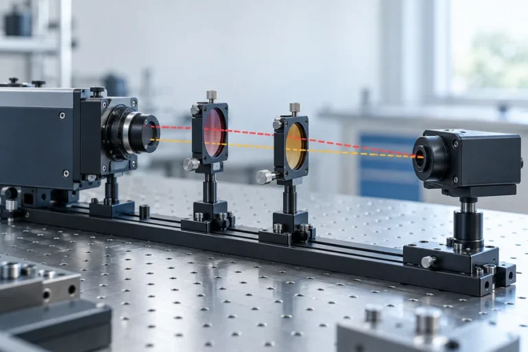
يحتاج كل ليزر حالة صلبة إلى ثلاث وظائف: إدخال الطاقة، والكسب البصري، والتغذية الراجعة. مصباح أو صمام ثنائي ليزري يوفر ضوء الضخ. يمتص وسط الكسب جزءًا من ذلك الضوء ويخزن الطاقة في أيونات مثارة. تشكل المرايا حول الوسط رنانًا، مع مرآة واحدة تنقل الخرج المفيد جزئيًا.
بمجرد أن ينتج الضخ انعكاسًا سكانيًا كافيًا، يمكن لفوتون عند انتقال الليزر أن يحفز أيونًا مثارًا لإصدار فوتون آخر بنفس التردد والعلاقة الطورية والاتجاه. تعمل المرور المتكررة عبر الرنان على تضخيم الأنماط البصرية المحددة حتى يتوازن الكسب مع فقد التجويف واقتران الخرج.
تتبع طاقة الفوتون المنبعث:
E = hc / λهنا،, E هي طاقة الفوتون،, h هو ثابت بلانك،, c هي سرعة الضوء، و λ هو الطول الموجي. لا تخبرك المعادلة بالطول الموجي للخرج بحد ذاتها؛ تحدد مستويات الطاقة للمادة المشوبة والمضيف وتصميم الرنان أي انتقال مدعوم يتذبذب.
الضخ: مصابيح الفلاش مقابل الصمامات الثنائية الليزرية
توفر مصابيح الفلاش ضوء ضخ واسع الطيف ويمكنها تنشيط أحجام كسب كبيرة نسبيًا، لكن قد يقع جزء كبير من طيفها خارج نطاقات الامتصاص المفيدة. يمكن اختيار الصمامات الثنائية الليزرية لمطابقة نطاق امتصاص بشكل أفضل. كما يدعم حجمها الصغير ومحركها القابل للتحكم حزمًا أصغر وأكثر كفاءة.
المطابقة ليست مجرد إدخال طول موجي على رسم. يتغير عرض الطيف الطيفي للمضخة وطولها الموجي المركزي مع التيار ودرجة الحرارة، بينما يمتلك وسط الكسب طيف امتصاص محدودًا. لذلك يجب أن تقارن المراجعة الهندسية طيف المضخة عبر نافذة التشغيل، وليس فقط عند درجة حرارة الغرفة.
تغير هندسة الضخ الأداء أيضًا. يمكن أن يوفر الضخ الطرفي تداخلًا قويًا بين أنماط المضخة والرنان. يمكن أن يوزع الضخ الجانبي الطاقة عبر حجم أكبر. لا يُعد أي منهما أفضل عالميًا؛ يعتمد القرار على حجم النمط المطلوب، والطاقة المخزنة، وجودة الحزمة، وغلاف الحزمة، ومسار إزالة الحرارة.
التشغيل المستمر الموجي والنبضي
ينتج ليزر الموجة المستمرة (CW) خرجًا مستدامًا تحت ظروف ثابتة. تطلق التصميمات النبضية الطاقة على فترات زمنية محددة. لا تقارنها باستخدام قدرة الخرج وحدها.
لسلسلة نبضات:
القدرة المتوسطة: P_avg = E_pulse × f_repE_pulse هي طاقة النبضة،, f_rep هو معدل التكرار، و τ هي مدة النبضة وفقًا لاتفاقية عرض محددة. تعبير القدرة القصوى هو تقدير ما لم يتم تضمين شكل النبضة. يمكن لمنتجين بنفس القدرة المتوسطة فرض متطلبات مختلفة جدًا للضرر البصري والكاشف والحراري.
يمنع التبديل Q التذبذب بينما تتراكم طاقة المضخة، ثم يخفض فقد التجويف بسرعة لإطلاق نبضة قصيرة وعالية الطاقة. تستخدم الأنظمة النشطة مُعدِّلًا داخل التجويف محكومًا؛ بينما تستخدم التصميمات السلبية غالبًا ممتصًا مشبعًا. يخدم قفل النمط غرضًا مختلفًا: فهو يثبت العلاقة الطورية بين الأنماط الطولية لتوليد سلاسل نبضات أقصر بكثير. عالج “النبضي” كفئة، وليس كمواصفة كاملة [2].
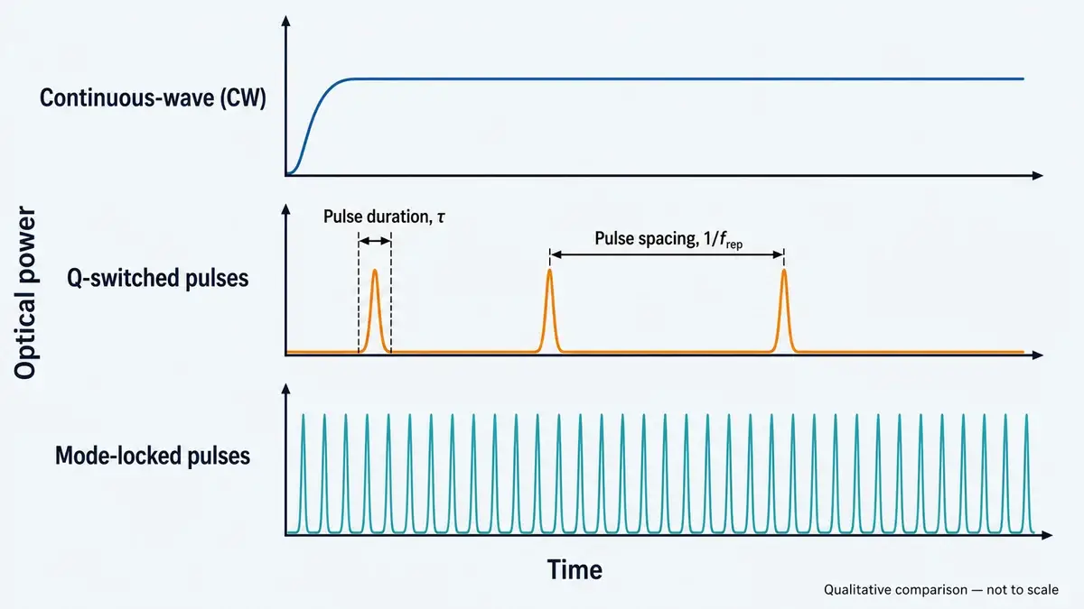
خرج CW مستمر، بينما تنتج مصادر التبديل Q وقفل النمط سلاسل نبضات على مقاييس زمنية مختلفة جدًا. مقارنة نوعية؛ ليست بمقياس.
وسائط الكسب الشائعة لليزرات الضخمة
يعمل الأيون النشط والمضيف كزوج. يمكن أن يؤدي تبديل المضيف مع الحفاظ على المادة المشوبة إلى تغيير الامتصاص، والمقطع العرضي للانبعاث، وعمر الحالة العلوية، وعرض النطاق، والتوصيل الحراري، وسلوك الاستقطاب. لهذا السبب لا يجب أن يحل اسم المادة محل مواصفة مصدر كاملة أبدًا.
| وسط الكسب | منطقة الخرج النموذجية | الطابع الهندسي | الملاءمة الشائعة ضمن التطبيقات المعتمدة |
|---|---|---|---|
| Nd:YAG | قرب 1064 نانومتر | منصة بلورية ناضجة بخصائص حرارية وميكانيكية مفيدة؛ تدعم التصميمات المستمرة والنبضية | الضخ الصناعي والأدوات العلمية |
| Nd:YVO4 | قرب 1064 نانومتر | الكسب العالي يمكن أن يدعم مذبذبات مدمجة منخفضة العتبة؛ يتطلب السلوك الحراري تصميمًا دقيقًا | الأدوات العلمية والمصادر البصرية المدمجة |
| Yb:YAG | قرب 1 ميكرومتر | فرق الطاقة الصغير بين المضخة والليزر يمكن أن يقلل من تسخين عيب الكم؛ يُستخدم غالبًا في البنى القابلة لتوسيع القدرة | مصادر الضخ الصناعية والبحثية |
| إر:زجاج | حول منطقة 1.5 ميكرومتر | الوسط الزجاجي يدعم تنسيقات مصادر مدمجة؛ السلوك الحراري والنبضي يعتمدان على التركيب والتغليف | تحديد المدى الدقيق، الليدار، والأدوات العلمية |
| تي:ياقوت | قابل للضبط على نطاق واسع في الأشعة تحت الحمراء القريبة | عرض نطاق الكسب الواسع يدعم أنظمة بحثية قابلة للضبط وذات نبضات فائقة القصر | الأدوات العلمية |
| روبي | حول 694 نانومتر | ليزر ثلاثي المستويات ذو أهمية تاريخية مع عتبة ضخ مرتفعة نسبيًا | البحث وتعليم فيزياء الليزر |
هذه المناطق الطيفية هي قيم استرشادية، وليست حدودًا للشراء. يعتمد الناتج الدقيق على تركيب المادة، الانتقال، بصريات التجويف، درجة الحرارة، وأي تحويل ترددي غير خطي. على سبيل المثال، يجب مراجعة مصدر مضاعف التردد كبنية كاملة بدلاً من وصفه فقط بطول موجة الناتج المرئي.
الوسطات الزجاجية والبلورية أيضًا تخلق مقايضات مختلفة. يمكن للزجاج أن يوفر مرونة في التركيب، أطيافًا واسعة، وأشكالًا قابلة للتكيف، بينما توفر العديد من الوسطات البلورية موصلية حرارية أقوى. عرض النطاق الواسع يمكن أن يكون قيمًا للقابلية على الضبط أو النبضات القصيرة، لكنه قد يأتي مع مقاطع عرضية انبعاثية أقل أو خصائص حرارية أضعف. اختيار وسط الكسب هو مشكلة تحسين، وليس ترتيبًا [3].
لماذا تستحق ليزرات الإربيوم-الزجاج اهتمامًا منفصلًا
ليزر Er:glass هو ليزر صلب الحالة السائبة حيث يوفر الزجاج المحتوي على الإربيوم الكسب. إنه ليس نفس البنية مثل ليزر الألياف المشبع بالإربيوم، حتى لو تداخلت مناطقها الطيفية.
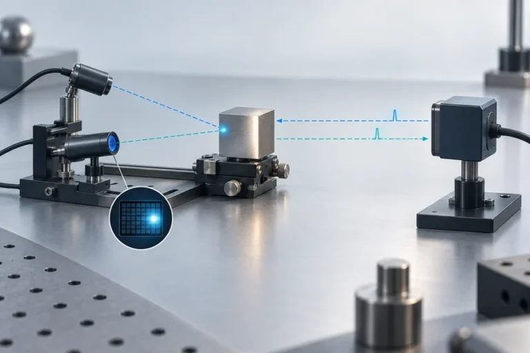
لتحديد المدى الدقيق والأدوات العلمية، يجب أن يربط تقييم المصدر طاقة النبضة، عرض النبضة، معدل التكرار، التباعد، محاذاة الحزمة، سلوك درجة الحرارة، واستجابة المستقبل. الطول الموجي وحده لا يحدد مدى النظام أو سلامة الليزر. يجب تقييم المنتج المكتمل تحت ظروف الانبعاث الفعلية القابلة للوصول باستخدام المعيار المناسب وإعداد القياس [4].
تطور LUMEXIS مصادر ليزر الإربيوم-الزجاج كواحدة من منصاتنا التكنولوجية الأربع المركّزة. نطاقنا الأوسع نهج تكنولوجيا الليزر يربط التصميم البصري بالتغليف، الإلكترونيات، البرامج الثابتة، الإدارة الحرارية، وتطوير طرق الاختبار بدلاً من معالجة المصدر كجزء بصري معزول.
البنى الليزرية السائبة ومقايضاتها
يمكن تشكيل وسطات الكسب السائبة كقضبان، ألواح، أقراص، أو بنى رقائقية مدمجة. تتحكم الهندسة في توزيع الضخ، نمط الرنان، نسبة السطح إلى الحجم، نمط الإجهاد، اتجاه التبريد، وحجم التغليف العملي.
القضيب مألوف وميكانيكيًا مباشر، لكن التدرجات الحرارية الشعاعية يمكن أن تنتج عدسة حرارية وإجهادًا. الألواح توزع الحرارة ويمكن أن تدعم مسارًا بصريًا أوسع، على الرغم من أن ترتيب الرنان والضخ يصبح أكثر تعقيدًا. تصميمات القرص الرقيق تزيل الحرارة بشكل رئيسي عبر اتجاه محوري قصير، مما يمكن أن يساعد في توسيع القدرة. ليزرات الرقاقة تقصر وتبسط التجويف لمصادر نبضية مدمجة، لكن التفاوتات الضيقة والمساحات البصرية الصغيرة تثير اعتبارات الطلاء والمحاذاة والتلف.
أفضل بنية هي تلك التي تبقى مستقرة عند نقطة التشغيل المطلوبة. العرض المخبري عند درجة حرارة اسمية لا يثبت أن الرنان سيحافظ على طاقة الناتج، الاتجاه، حجم النمط، وتوقيت النبضة بعد الإحماء أو عبر نطاق بيئي محدد.
مزايا وقيود مصادر الليزر السائبة
يمكن للمنصات الصلبة أن تجمع بين التغليف المدمج، خيارات الطول الموجي الواسعة، تخزين الطاقة القوي، والتحكم الزمني الدقيق. الضخ بالديود يمكن أن يحسن الجدوى الكهربائية والحرارية مقارنة بالضخ بالمصباح واسع النطاق. يمكن للوسطات السائبة أيضًا توفير مناطق نمط بصري أكبر من العديد من أجهزة الموجة الموجهة، وهو مفيد عندما تكون طاقة النبضة مهمة.
القيود مهمة بنفس القدر. طاقة الضخ الممتصة التي لا تخرج كناتج ليزر مفيد تتحول إلى حرارة. التدرجات الحرارية تغير معامل الانكسار، تخلق إجهادًا، ويمكن أن تشوه الأسطح البصرية. قد تكون النتيجة عدسة حرارية، إزالة استقطاب، تدهور الحزمة، عدم استقرار الرنان، انجراف الطول الموجي، أو تقليل عمر المكون [3].
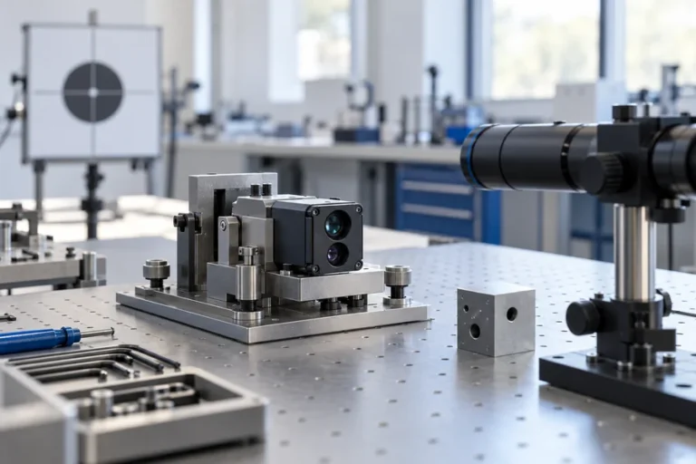
التجاويف ذات المساحة الحرة تعتمد أيضًا على المحاذاة. الحركة الميكانيكية، سلوك المواد اللاصقة، تلوث الطلاء، إجهاد اللحام، والتمدد الحراري يمكن أن يغيروا الأداء حتى عندما اجتاز كل مكون فردي فحص الوصول. يجب تصميم الموثوقية في المكدس البصري والميكانيكي والكهربائي والحراري معًا.
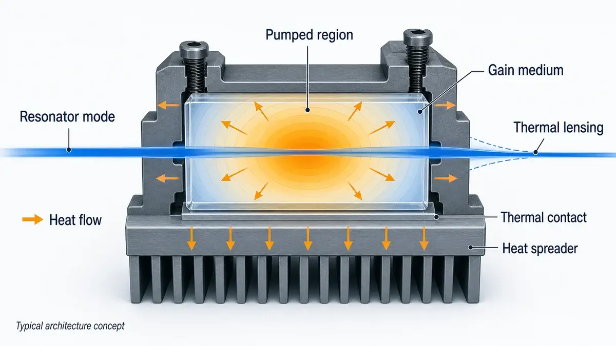
مقطع نوعي لليزر سائب يوضح كيف يمكن للحرارة أن تنتقل من المنطقة المضخوخة إلى الحامل بينما يغير التدرج الحراري نمط الرنان. مفهوم بنية نموذجي.
كيفية اختيار ليزر الحالة الصلبة
ابدأ بالمهمة البصرية، وليس بوسط كسب مفضل. حدد ما يجب أن ينتجه المصدر عند واجهة النظام وتحت أي ظروف. الطول الموجي هو فقط البوابة الأولى.
حدد الناتج في مجموعات كاملة
للتشغيل المستمر، حدد القدرة الضوئية مع درجة حرارة التشغيل، حالة القيادة، سلوك الإحماء، قطر الحزمة، التباعد أو M²، الاستقطاب، وفاصل الاستقرار. للتشغيل النبضي، احتفظ بطاقة النبضة، المدة، معدل التكرار، القدرة المتوسطة، ارتعاش التوقيت، واستقرار النبضة إلى النبضة معًا.
اسأل كيف تم قياس كل رقم. قد يشير “قطر الحزمة” إلى عرض 1/e²، FWHM، أو تعريف آخر. قد يكون التباعد زاوية كاملة أو نصف زاوية. قد يكون عرض النبضة FWHM بينما يفترض حساب القدرة القصوى نبضة مستطيلة. هذه التناقضات يمكن أن تنتشر إلى بصريات غير صحيحة، تشبع المستقبل، أو ميزانيات حرارية.
نمذجة الواجهات
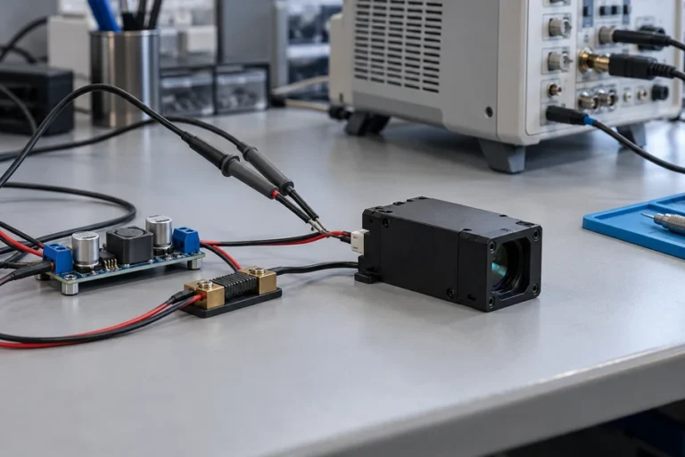
يتفاعل المصدر مع إلكترونيات القيادة، أسطح التركيب، المشتتات الحرارية، البصريات، الكواشف، البرامج الثابتة، والغلاف. وثق سلوك التيار والجهد المسموح، مستويات التشغيل، التأريض، مخطط دبابيس الموصل، استواء التركيب، المقاومة الحرارية، موضع المحور البصري، والتعرض للانعكاس الخلفي.
بالنسبة لتصميم المضخة بالديود، تستحق جودة المضخة نفس الانضباط. حجم قلب الألياف، والفتحة العددية، وتنسيق الموصل أو اللحام، وكفاءة الاقتران، وسلوك الطول الموجي مع درجة الحرارة، وإدارة الضوء المرتجع، كلها تؤثر على طاقة المضخة المُسلَّمة وعمرها الافتراضي. حلولنا حلول الليزر المقترنة بالألياف مُطوَّرة حول توصيل شعاع مُتحكم فيه وتكامله بدلاً من طاقة الباعث بمعزل عن الآخرين.
اختبر نافذة التشغيل الفعلية
القيم النموذجية في درجة حرارة الغرفة ليست خطة تأهيل. اطلب البيانات عند درجة الحرارة ذات الصلة، ودورة التشغيل، ومعدل التكرار، وحالة التركيب، وحالة الإحماء. إذا كان الجهاز يعمل ديناميكيًا، فقم بتضمين التحولات بدلاً من القياس فقط بعد التوازن.
يمكن للدورات الحرارية أن تكشف عن انزياحات المحاذاة وإجهاد الوصلات البينية. يمكن أن يساعد فحص الاحتراق أو الشيخوخة في تحديد الأعطال المبكرة في العمر. قد يكون الختم المحكم ذا صلة عندما يمكن أن تؤثر الرطوبة أو التلوث على الطلاءات أو الأسطح أو الروابط، ولكن يجب أن يدعم تصميم العبوة وأدلة اختبار التسرب هذا الادعاء.
راجع سلامة الليزر على مستوى المنتج
لا تستنتج أبدًا فئة السلامة من الطول الموجي وحده. يعتمد التصنيف على الانبعاث المتاح، وخصائص النبضة، ومدة التعرض، والفتحة، وهندسة الشعاع، وسلوك المسح، وبناء المنتج. يغطي معيار IEC 60825-1 تصنيف ومتطلبات منتجات الليزر عبر نطاق 180 نانومتر إلى 1 ملم؛ يجب على مُصنِّع النظام النهائي تقييم المنتج المكتمل بموجب القواعد المعمول بها [4].
قارن مخاطر دورة الحياة، وليس سعر الوحدة فقط
يمكن أن يُلغى سعر الشراء المنخفض بسبب إعادة التصميم الحراري، أو الانجراف الميداني، أو الدفعات غير المتسقة، أو فترات الاستبدال الطويلة، أو تغييرات العمليات غير الموثقة. اسأل عن ما يتم التحكم فيه عند الفحص الوارد، والتجميع، والمحاذاة، والختم، والفحص، والاختبار النهائي. إمكانية التتبع والتحكم في التغيير هما متطلبان تجاريان بقدر ما هما متطلبان للجودة.
تصفح حلولنا الحالية محفظة مصادر الليزر والوحدات النمطية لمعرفة كيف يتم فصل الطول الموجي، وهندسة المصدر، وتنسيق الحزمة على مستوى المنتج.
ما الذي يجب البحث عنه في مورد مصادر الليزر
يجب على المورد الموثوق ترجمة المواصفات الرئيسية المطلوبة إلى حالة تشغيل قابلة للاختبار. إذا طلبت طاقة نبضة، يجب أن يتناول الرد أيضًا معدل التكرار، وتعريف عرض النبضة، ودرجة الحرارة، ونقطة التشغيل، وطريقة أخذ العينات، والتباين المقبول. إذا طلبت جودة الحزمة، يجب أن يكون مستوى القياس والطريقة واضحين.
في LUMEXIS، يربط فريقنا بين التصميم البصري والكهربائي البصري وتغليف ليزر أشباه الموصلات، واقتران الألياف، والإلكترونيات، والبرامج الثابتة، وخوارزميات قياس المدى للإشارات الضعيفة، والتصميم الحراري. يمكن أن تشمل خطوات الإنتاج فحص الوارد، واختبار الرقائق، وربط القوالب، واللحام، والمحاذاة، والختم المحكم، وفحص التقادم، واختبار الأداء النهائي. تعتمد العملية الدقيقة على المصدر والحزمة.
لمناقشة التأهيل، اطلب أدلة ذات صلة بحالة الاستخدام الخاصة بك: بيانات معتمدة على درجة الحرارة، وظروف الحرق، وتحمل المحور البصري، وإعداد قياس النبضة، وإمكانية تتبع الدفعات، ومعايير القبول. لا يمكن لشهادة عامة أو رسم بياني بدرجة حرارة الغرفة أن تحل محل هذه التفاصيل.
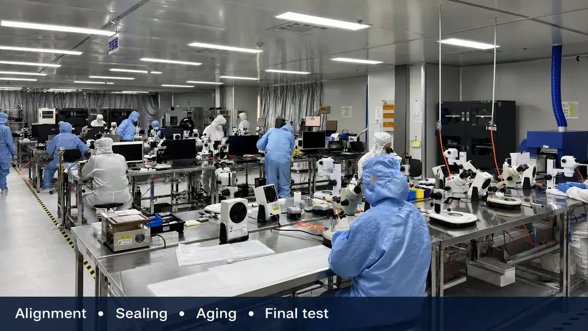
يساعد التجميع المتحكم فيه، والمحاذاة، والختم، والتقادم، والاختبار النهائي في ترجمة التصميم البصري إلى أجهزة إنتاج قابلة للتكرار.
الأسئلة الشائعة
ما هو الفرق الرئيسي بين ليزر الحالة الصلبة وليزر الصمام الثنائي؟
يولد ليزر الحالة الصلبة التقليدي خرجه في بلورة أو زجاج مشوب يتم ضخه بصريًا. يولد ليزر الصمام الثنائي الضوء من خلال إعادة تركيب الإلكترونات والثقوب في وصلة أشباه الموصلات. يحتوي ليزر DPSS على كليهما: يوفر الصمام الثنائي ضوء الضخ، وتنتج وسيلة الكسب السائبة المنفصلة خرج الرنان.
هل ليزر الألياف هو ليزر حالة صلبة؟
فيزيائيًا، أليافه الزجاجية المشوبة صلبة، لذا ينتمي ليزر الألياف إلى عائلة الحالة الصلبة الأوسع. في الاستخدام التجاري والهندسي، عادةً ما يتم التعامل مع ليزرات الألياف بشكل منفصل عن ليزرات الحالة الصلبة السائبة لأن دليل الألياف الموجي يتحكم في الوضع البصري، واقتران الضخ، والسلوك الحراري، والتأثيرات غير الخطية، وهندسة الحزمة.
ما هي أكثر مواد ليزر الحالة الصلبة شيوعًا؟
تشمل الوسائط الشائعة Nd:YAG، وNd:YVO4، وYb:YAG، وEr:glass، وTi:sapphire، والياقوت. يجمع التصنيف بين أيون نشط ومضيف، وكلاهما مهم. قارن الامتصاص، وطول موجة الانبعاث، وعرض النطاق، وعمر الحالة العلوية، والتوصيل الحراري، والخصائص الميكانيكية، والنظام المطلوب للموجة المستمرة أو النبضية قبل الاختيار.
ما هو ليزر الحالة الصلبة ذو التبديل Q؟
يخزن ليزر التبديل Q طاقة الضخ في وسيط الكسب الخاص به بينما يتم إبقاء فقدان الرنان مرتفعًا. عندما يتم خفض الفقد، يتم إطلاق تلك الطاقة المخزنة كنبضة قصيرة عالية الذروة. لا تزال المواصفات تحتاج إلى طاقة النبضة، والعرض، ومعدل التكرار، ومتوسط الطاقة، والاستقرار، وظروف التشغيل؛ “التبديل Q” وحده غير مكتمل.
لماذا تعتبر الإدارة الحرارية حاسمة في ليزرات الحالة الصلبة؟
لا تتحول كل طاقة الضخ الممتصة إلى خرج ليزر. تخلق الحرارة المتبقية تدرجات حرارية يمكن أن تغير معامل الانكسار، وتسبب إجهادًا ميكانيكيًا، وتشوه الأسطح. قد تغير هذه التأثيرات جودة الحزمة، والمحاذاة، والكفاءة، وسلوك النبضة، والعمر الافتراضي، لذا يجب تصميم وسيط الكسب، والحامل، ومسار التبريد، والرنان معًا.
هل ليزرات الحالة الصلبة بطول موجة 1.5 ميكرومتر آمنة للعين تلقائيًا؟
لا. يؤثر الطول الموجي على كيفية تفاعل الإشعاع مع العين، لكنه لا يحدد فئة السلامة بحد ذاته. الانبعاث المتاح، وطاقة النبضة ومدتها، ونمط التكرار، والفتحة، والتباعد، وظروف التعرض، والضمانات الوقائية للمنتج كلها مهمة. صنف منتج الليزر المكتمل باستخدام المعيار المطبق والقياسات الموثقة.
إذا كنت تختار مصدر حالة صلبة سائبة، أو ليزر زجاج الإربيوم، أو هندسة الضخ الخاصة به، فأحضر لنا نافذة التشغيل وقيود الواجهة، وليس مجرد طول موجي مستهدف. تحدث إلى مهندسينا حول مسار المصدر والتأهيل الذي يناسب الجهاز.
المراجع
N. Hodgson وH. Weber،, هندسة ليزر الحالة الصلبة, ، CREOL، جامعة وسط فلوريدا: ليزرات الحالة الصلبة. R. Paschotta، موسوعة RP Photonics: التبديل Q. R. Paschotta، موسوعة RP Photonics: وسائط كسب الليزر و العدسة الحرارية. اللجنة الكهروتقنية الدولية،, IEC 60825-1:2014 — سلامة منتجات الليزر، الجزء 1.