





Two optical sensors can both output millimeters and still solve different problems. A device chosen from one accuracy line may fail when the target tilts, the standoff changes, the return crosses a protective window, or the host expects a distance faster than the receiver can qualify it.
That mismatch creates redesign work late in integration. The useful question is not which technology is better in isolation, but which measurement observable remains reliable inside your target, geometry, speed, and environment.
In a triangulation vs time of flight sensor decision, choose triangulation for controlled close-range displacement or profile measurement when fine position change matters. Choose ToF when the system needs a larger standoff or broader ranging envelope. In either case, validate the actual target, angle, window, ambient light, speed, and reporting behavior before design freeze.
Triangulation vs time of flight sensor: the deciding difference
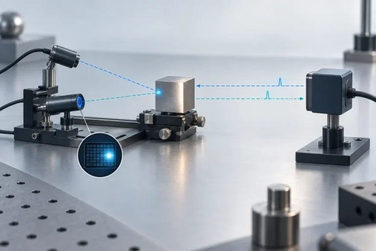
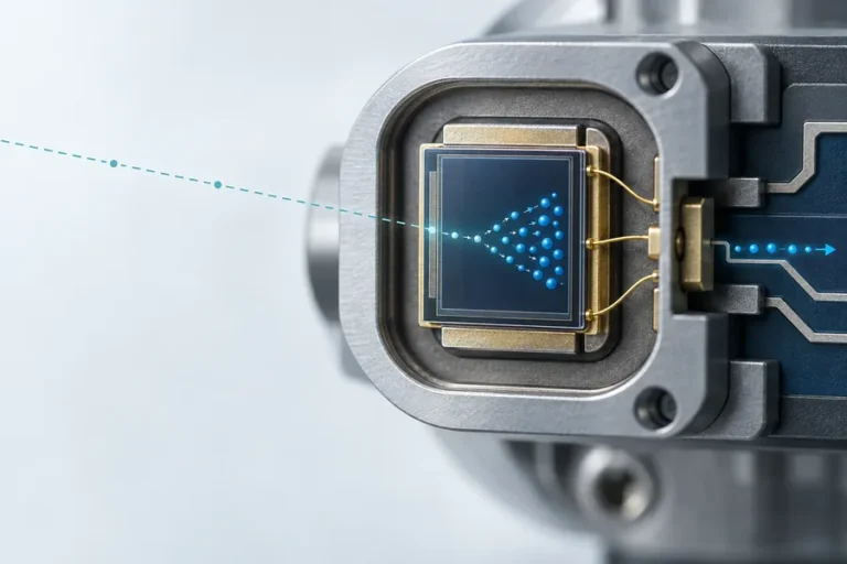
A laser triangulation sensor projects a spot onto the target and views the reflected spot through a receiver that is offset from the emitter. As the target moves, the return angle changes, so the spot lands at a different position on a PSD, CCD, or CMOS receiver. Calibration converts that image position into distance or displacement.
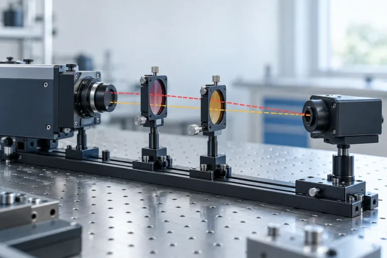
A time-of-flight distance sensor measures a temporal quantity instead. In direct ToF, the receiver identifies the delay between emission and return; the basic relation is d = cΔt / 2, where the factor of two accounts for the outward and return path. Indirect ToF estimates distance from the phase shift of a modulated signal. Our guide to time-of-flight distance measurement explains the ranging chain in more detail.
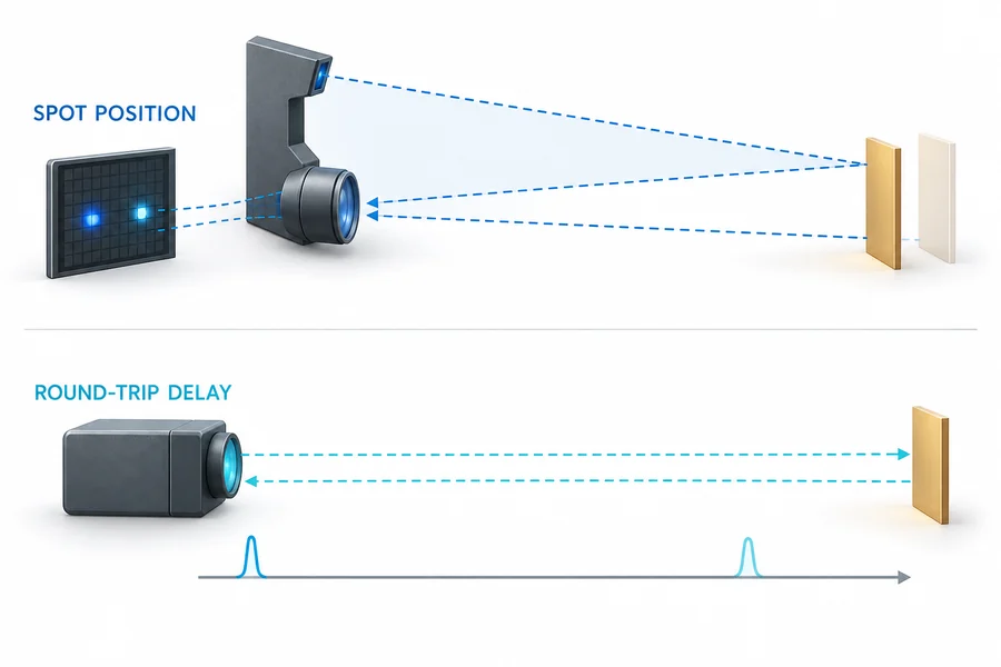
This distinction shapes the hardware. Triangulation needs a known emitter-to-receiver baseline and enough angular change across its measuring range. ToF needs a transmitter, receiver, timing or phase electronics, and signal processing able to separate a valid return from noise and competing paths. Neither architecture is defined by the laser alone.
Do not collapse every ToF device into one class. Direct and indirect implementations have different ambiguity, timing, modulation, and processing constraints. We compare those architectures separately in direct ToF versus indirect ToF.
Compare the specifications without mixing measurement terms
The familiar shorthand says triangulation offers finer close-range measurement while ToF covers more distance. That is a useful starting point, not a purchase specification. Compact ToF devices can operate at short range, and triangulation systems can be built for different standoffs. The exact result depends on optics, detector, calibration, target, exposure, processing, and test method.
Keep these terms separate:
- Measuring range is the interval over which the supplier states that the sensor can return data under defined conditions.
- Accuracy compares the reported result with a traceable reference or stated true value.
- Repeatability describes the spread when the same condition is measured repeatedly.
- Resolution is the smallest reported or detectable change; it does not prove absolute accuracy.
- Response time or sampling rate describes when new data becomes available, but filtering and averaging may change latency.
- Spot size and receiver field determine what portion of the scene can influence the result.
| Selection factor | Laser triangulation | Time of flight |
|---|---|---|
| Measured observable | Return-spot position on an imaging element | Pulse delay or modulation phase |
| Typical strength | Fine displacement or profile changes in a controlled working envelope | Distance measurement across a broader standoff or ranging envelope |
| Geometry dependency | Requires a stable baseline and clear emitter/receiver views | Requires transmitter/receiver field overlap and a separable return path |
| Common target risk | Surface angle, specular return, edge transitions, occlusion, color or texture variation | Weak return, background light, multipath, window reflections, partial beam interception |
| Datasheet check | Standoff, span, linearity, repeatability, spot shape, sampling conditions | Range conditions, target definition, valid-return rule, update mode, ambiguity and filtering |
| Best validation output | Raw displacement plus signal/quality indicator | Raw distance plus status, return identity, confidence or invalid code where available |
When two datasheets use different targets or filtering, the numbers are not directly comparable. Ask for the target, distance, angle, illumination, temperature, exposure or averaging, sample condition, and success criterion behind each value. Then reproduce the relevant conditions using a controlled laser rangefinder range test.
Geometry and target behavior decide which sensor survives integration
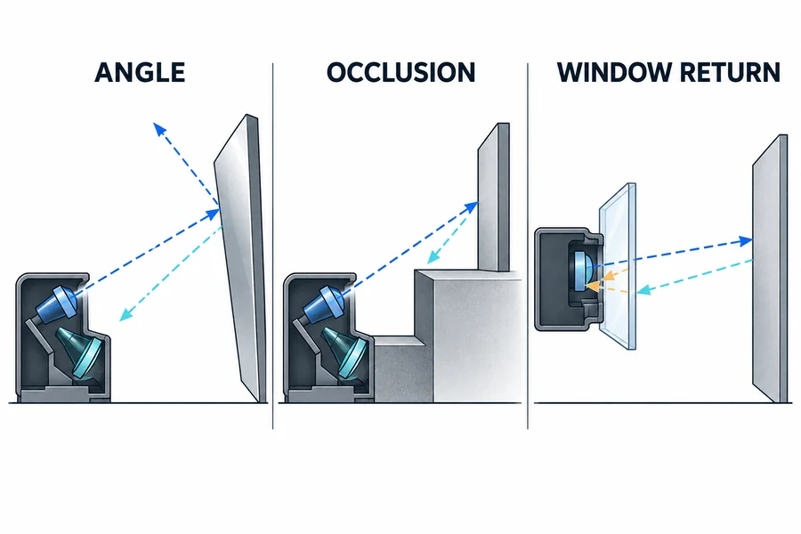
Triangulation derives sensitivity from geometry. The baseline and receiver angle make target motion visible as spot motion on the array, but they also create a directional field of view. A step, recess, or foreground edge can illuminate a point that the receiver cannot see. Rotating the target can send most specular energy away from the receiving lens or move an elongated spot across the detector.
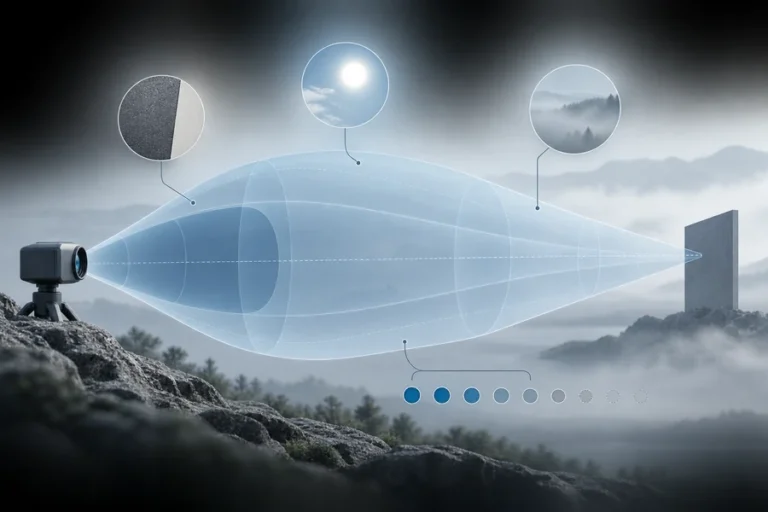
ToF is often arranged with smaller separation between transmit and receive axes, but it is not immune to geometry. A small or angled target may return too little energy. A foreground edge can mix with the intended target. A nearby enclosure surface or protective window can create an early path that competes with the desired return. Background light consumes receiver margin even though the distance is calculated from timing rather than brightness alone.
Treat the target as an optical boundary, not just a color name. Record material, finish, size, curvature, angle, motion, distance, background, contamination, and expected temperature. Our target reflectivity guide explains why visible appearance is not a complete description of the return.
The host window deserves its own review. For triangulation, it must preserve both the projected path and the offset receiver view over the full working span. For ToF, it must control near-field reflections and keep the transmit and receive paths from coupling inside the enclosure. In both cases, verify the installed window, coating, angle, clear aperture, cleanliness, and tolerance stack.
Use the application to choose the architecture
Favor triangulation when the engineering question is a small position change inside a controlled working envelope: height, thickness, runout, edge position, step, or a scanned surface profile. It is especially useful when the sensor can be mounted rigidly, the target presentation is repeatable, and the receiver has an unobstructed view.
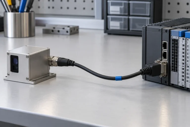
Favor ToF when the question is absolute distance across a larger or changing standoff: ranging to civil structures, position on a long machine axis, level or clearance measurement, or integration into a compact instrument. A laser rangefinder module can combine the transmitter, receiver, timing, processing, and host interface, but the finished system still owns the mount, window, target conditions, software, and acceptance test. The current Lumexis laser rangefinder module family provides the model-specific starting point.
An overlap zone does not mean either method will work equally well. In a triangulation vs time of flight sensor shortlist, let the target and installation break the tie when the required distance and precision fall inside both product families. A stable diffuse surface at fixed standoff may favor triangulation. A changing standoff, tight packaging around the optical axes, or a broader ranging task may favor ToF. Transparent, highly specular, very dark, or mixed-depth targets require application-specific testing for either method.
Validate the choice with a controlled comparison
Begin with one reference target and one traceable distance or displacement setup. Freeze the sensor configuration, supply, warm-up state, mount, window, target size, angle, background, ambient light, filter settings, and host logging. Define acceptable error, repeatability, invalid-return rate, latency, and recovery behavior before collecting data.
Then change one factor at a time. A useful sequence is distance, target material, target angle, edge position, motion, ambient light, window condition, temperature, and supply variation. Preserve raw values and quality or status fields; a filtered distance alone can hide dropouts, mode changes, and outliers.
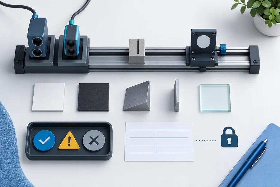
Finally, repeat the important cases in the host enclosure with final mechanics, power, cabling, and software. The supplier’s component test and the OEM’s installed-system acceptance answer different questions. LUMEXIS engineering services can support model selection, optical and mechanical integration, interface review, validation planning, and troubleshooting across pre-sales and after-sales stages.
Our Wuxi engineering and commercial office works with a 14,000-square-meter Taizhou manufacturing base. Cleanroom assembly, controlled optical alignment, hermetic packaging where applicable, aging or burn-in screening, temperature cycling, and final performance testing help convert a validated configuration into repeatable production. These capabilities support the evidence chain; they do not replace validation in your completed instrument.
Frequently asked questions
Is ToF always less accurate than triangulation?
No. The architecture suggests typical strengths, but the result belongs to a specific device, range, target, configuration, and test method. A high-quality ToF sensor can outperform an unsuitable triangulation setup in its intended task. Compare accuracy and repeatability under matched conditions rather than using the family name as the pass criterion.
Can triangulation measure a dark or glossy target?
Sometimes, if enough usable return reaches the imaging element and the sensor can control exposure or gain without corrupting the spot estimate. Dark, glossy, textured, transparent, or strongly angled surfaces can change spot shape and intensity. Test the actual material across the required angle and distance envelope.
Does ToF ignore target reflectivity?
No. Timing determines distance, but the receiver still needs a return with adequate signal quality. Reflectivity, target size, angle, beam footprint, background light, atmosphere, receiver aperture, and processing all affect whether the correct return can be detected and qualified.
Which method handles angled surfaces better?
There is no universal winner. Triangulation is explicitly sensitive to the return angle and receiver view, while ToF still depends on enough energy returning within the receiver field. Compare the actual incidence angles, surface finish, spot size, target size, and mounting constraints in a controlled test.
Can both methods work through a protective window?
Yes, but the window becomes part of the optical system. Verify wavelength transmission, coating, wedge or tilt, thickness, clear aperture, contamination, and internal reflections. Triangulation must preserve its offset geometry; ToF must prevent near-field leakage or multipath from masking the desired return.
References
- OMRON, Displacement Sensor Technical Guide, especially the laser-triangulation principle and receiver-element discussion.
- ams OSRAM, Time-of-Flight Measurement Using Pulse Lasers, Application Note AN106.
- STMicroelectronics, Time-of-Flight Principles, Challenges, and Performance.
- KEYENCE, Position Recognition Type Laser Sensor Principles.
Choosing a measurement method for an OEM design? Send our applications engineers the distance envelope, required accuracy and repeatability, target materials and angles, measurement rate, optical window, ambient conditions, interface, annual volume, and fixed mechanical constraints. We can recommend a standard laser rangefinder module or review a custom or private-label requirement with its own qualification scope and lead time.