

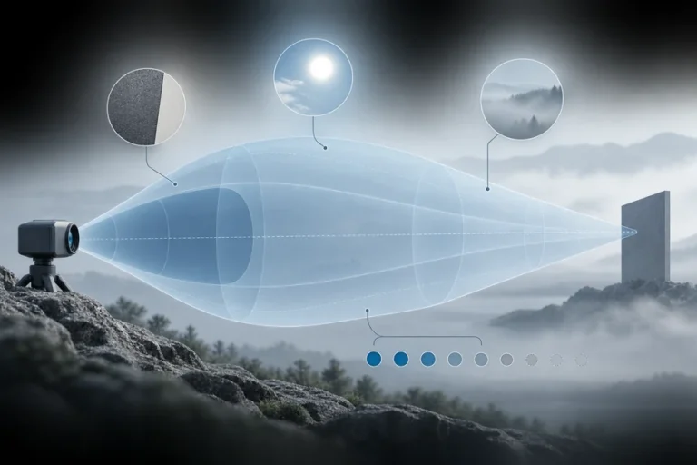

Rangefinder target reflectivity describes how strongly a target returns incident optical energy under a stated wavelength and measurement geometry. With other conditions held constant, a higher-reflectance target usually sends more energy back to the receiver and is easier to detect at distance. But 10%, 30%, and 90% are best treated as low-, medium-, and high-return reference conditions—not as a universal industry rule.
A reflectivity percentage alone cannot predict maximum range. Target size, surface directionality, incidence angle, ambient light, atmosphere, receiver processing, and the required probability of detection all affect the result. Those conditions must travel with any credible range specification.
Why Target Reflectivity Changes Rangefinder Performance
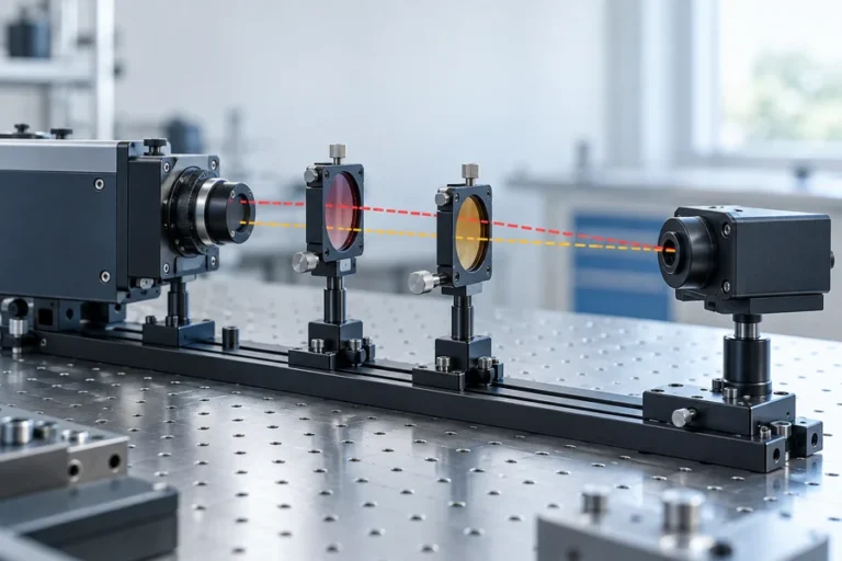
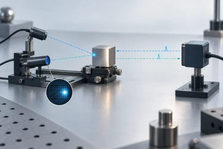
A pulsed time-of-flight rangefinder transmits a short optical pulse, receives a small portion of the returned energy, and converts the measured delay into distance. Our guide to how a laser rangefinder works explains that signal chain in more detail.
Only a fraction of transmitted energy reaches the detector. Some energy spreads before reaching the target. The target then absorbs, transmits, scatters, or redirects the incident light. The receiver captures only the portion that returns within its aperture and acceptance conditions. A low-reflectance target therefore reduces the received-signal margin relative to background and receiver noise.
NIST laser-scanner calibration experiments also show why “more reflective is always better” is too simple. Low-reflective targets became less precise at longer ranges in those tests, while highly reflective targets produced larger errors at short range. The exact response depends on the instrument, but the broader lesson is useful: reflectivity can influence both whether a return is detected and how the measurement behaves after detection.
Reflectivity Is Spectral, Not Just Visible Color
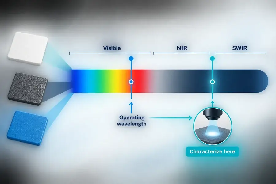
A surface that looks black or white to the eye does not necessarily have the same relative reflectance at 905 nm, 1064 nm, 1535 nm, or another laser wavelength. NIST maintains spectral reflectance measurement scales across ultraviolet, visible, and near-infrared regions from 250 nm to 2500 nm. That metrology work distinguishes several measurement geometries, including directional-hemispherical and bidirectional reflectance.
For rangefinder evaluation, a useful target certificate or characterization should therefore identify:
- reflectance at or near the operating wavelength;
- the measurement geometry and reference standard;
- the target surface and its spatial uniformity;
- calibration uncertainty and date, when available.
“Black panel” is a visual description. “10% reflectance at the operating wavelength under a stated geometry” is an engineering condition.
Diffuse and Directional Surfaces Behave Differently
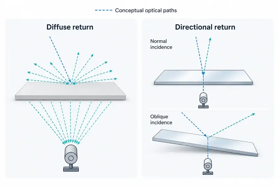
Nominal reflectance does not fully describe where the reflected energy goes. A near-Lambertian reference panel distributes energy broadly and is often used to make test geometry more repeatable. A glossy or retroreflective surface can direct energy strongly in particular directions. At oblique incidence, a high-reflectance glossy target may redirect much of the return away from the receiver.
The same issue appears with real targets. Painted metal, glass, wet surfaces, fabrics, concrete, vegetation, and coated panels have different angular and spectral behavior. Target orientation can therefore change returned signal even when material and distance do not change.
What 10%, 30%, and 90% Mean in Practice
The three values are useful as reference classes because they span a wide return-strength range. They do not replace a complete test specification.
| Reference condition | What it stresses | Useful engineering question | Main caveat |
|---|---|---|---|
| About 10% | Low-return detection margin | Can the system meet the required range on a demanding target? | Not every dark object has 10% reflectance at the laser wavelength. |
| About 30% | Mid-return comparison | Are two range claims comparable under a moderate target condition? | 30% is common in some datasheets, but it is not a universal “typical target.” |
| About 90% | Strong-return behavior | Does the receiver remain stable across high and near-range returns? | Strong reflectance can expose saturation or short-range bias in some instruments. |
10%: A Demanding Low-Return Condition
A 10% target is often used as a challenging range condition, especially in LiDAR and ranging evaluations. It is valuable because it reduces return margin and can reveal where background, atmosphere, target extent, or receiver thresholds begin to dominate.
Do not translate “10%” directly into a named real-world color or material. A road surface, coating, textile, or natural object can differ substantially by wavelength, moisture, finish, and incidence angle. Use the value as a controlled reference point, then validate representative application targets separately.
30%: A Mid-Return Comparison Point
Many supplier specifications state range against a 30% target. That can be a useful middle condition, but only when the accompanying test conditions match. A 30% result collected indoors against a large normal-incidence panel cannot be compared directly with a 30% result collected outdoors against a small angled target under strong background light.
When comparing modules, look beyond the percentage. The laser rangefinder module datasheet guide lists the additional conditions needed to interpret a range claim.
90%: A High-Return Reference
A 90% panel represents a strong-return condition. It can be useful for checking high-return performance, receiver dynamic range, and near-range behavior. It should not be used alone to communicate practical maximum range because it may hide the more demanding low-return boundary.
High reflectance also does not guarantee lower error at every distance. Receiver saturation, pulse-shape distortion, threshold behavior, and multipath can affect some architectures. Test both the long-range low-return boundary and the short-range high-return boundary when the application spans a wide dynamic range.
Reflectivity and Detection Probability Are Different Percentages
This distinction prevents one of the most common specification mistakes:
- Target reflectivity describes an optical property or test condition of the target.
- Probability of detection describes how often the sensor produces a valid detection under a defined trial, frame, or pulse criterion.
A 90% reflectivity target is not the same as 90% probability of detection. In a peer-reviewed automotive LiDAR test-system paper, the authors treated a target as detected when it appeared in at least 90% of sensor outputs. That 90% was the success criterion, not the panel reflectivity. The same paper recommended measurements with several known reflectivity levels, such as 10%, 20%, and 40%, illustrating that test tiers vary.
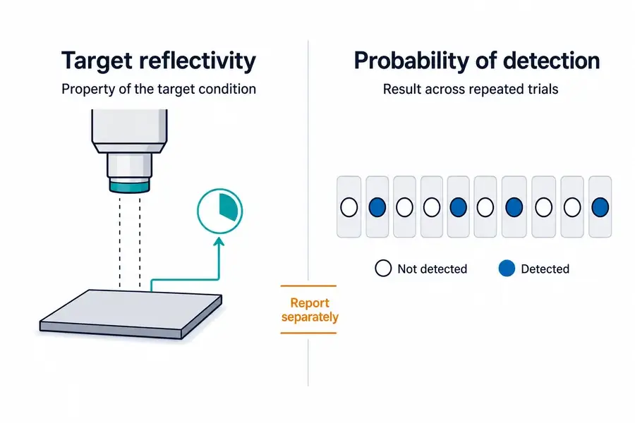
A useful report should state both values separately: for example, the characterized target reflectance and the proportion of valid detections over a stated number of trials. It should also define what counts as valid, including any accuracy window, confidence field, or rejection rule.
Conditions Needed for a Fair Range Comparison
Two maximum-range numbers are comparable only when their boundary conditions are substantially aligned.
Target and Geometry
Record the target dimensions, whether the illuminated footprint stays fully on the target, incidence angle, surface finish, alignment, and distance. Partial footprint coverage changes the composite return. An angled panel changes both projected area and scattering direction.
Sensor and Environment
Record the wavelength, optical configuration, update rate or integration settings, ambient illuminance, background position, atmospheric visibility, and temperature if relevant. Sunlight and other background sources can raise the receiver noise floor, so an indoor dark-room result and a bright outdoor result describe different operating points.
Detection Criterion
State the number of trials, the required detection probability, the allowable distance error, and the treatment of invalid or false returns. “Detected once” and “valid in 95 of 100 trials” are not equivalent claims.
Use this condition set when reading a datasheet:
| Field | Value to capture |
|---|---|
| Maximum or specified range | Distance and units |
| Target reflectance | Percentage at stated wavelength/geometry |
| Target dimensions | Width, height, and footprint coverage |
| Incidence angle | Normal or defined angular range |
| Ambient condition | Illuminance, background, visibility, weather |
| Wavelength | Nominal operating wavelength |
| Detection criterion | Valid-return rule and probability |
| Repeats | Pulses, frames, trials, and aggregation |
A Repeatable Target-Reflectivity Validation Plan
- Choose characterized panels. Use reflectance data at the rangefinder wavelength rather than visible appearance alone.
- Fix the geometry. Control panel size, distance, alignment, incidence angle, and footprint coverage.
- Define low, middle, and high return classes. Exact 10%, 30%, and 90% panels are useful when they match the specification, but adjacent documented values can also support a valid test plan.
- Control the environment. Record background light and atmospheric conditions; change one variable at a time during baseline testing.
- Repeat each condition. Count valid readings, invalid readings, and false returns over a stated sample size.
- Report two percentages separately. Keep panel reflectance distinct from probability of detection.
- Add application-relevant cases. Repeat at expected target angles, materials, backgrounds, and environmental limits.
This method does not create a universal performance curve, but it makes supplier comparisons and integration decisions more traceable.
What to Send a Rangefinder Module Supplier
For a useful module recommendation, describe the target and test conditions rather than asking only for “maximum range.” Include:
- required distance and representative target material or reflectance class;
- minimum target dimensions and expected incidence angles;
- ambient-light, visibility, and environmental conditions;
- required probability of detection and update rate;
- accuracy, size, mass, power, and interface constraints;
- wavelength or eye-safety constraints at the finished-system level.
Lumexis supports compact laser rangefinder module selection for civil, industrial, and research systems. You can also review the role of the optical source in our ranging laser source overview before sharing your integration conditions with the engineering team.
Frequently Asked Questions
Is 10% reflectivity the same as a black target?
No. “Black” describes visible appearance, while 10% reflectivity must be tied to a wavelength and measurement geometry. A visibly dark surface may reflect differently in the near-infrared or short-wave infrared.
Is the 10%/30%/90% grouping an industry standard?
No universal mandatory standard was identified in the reviewed sources. These values are useful low-, mid-, and high-return reference conditions, but other test methods use values such as 10%, 20%, 40%, 50%, or 80%.
Does doubling target reflectivity double maximum range?
Not necessarily. Simplified range equations can describe a conditional relationship, but practical results also depend on target extent, geometry, optics, processing, ambient light, atmosphere, and receiver limits. Use measured, condition-matched data for decisions.
Why can a glossy target return less signal at an angle?
A glossy surface may reflect energy strongly in a narrow direction. When tilted, that direction can move away from the receiver, reducing captured return even if the material has high nominal reflectance.
What should a rangefinder datasheet state next to maximum range?
At minimum: target reflectance and size, wavelength, incidence geometry, ambient condition, and detection criterion. Trial count, accuracy window, update settings, and atmospheric visibility make the result more reproducible.
How should probability of detection be reported?
State the valid-detection definition, number of trials, and fraction or percentage of valid returns for each test condition. Keep it separate from the target reflectivity percentage.
References
- National Institute of Standards and Technology. Spectral Reflectance and Transmittance.
- Cheok, G. S., Leigh, S. D., and Rukhin, A. L. Calibration Experiments of a Laser Scanner, NISTIR 6922.
- Gomes, T. et al. Evaluation and Testing System for Automotive LiDAR Sensors. Applied Sciences, 2022, 12, 13003.
- Garmin Support. Effects of Distance, Target Size, Aspect, and Reflectivity on Returned Signal Strength.
- National Institute of Standards and Technology. Methods to Evaluate 3D Lidars Used for Automated Driving.