


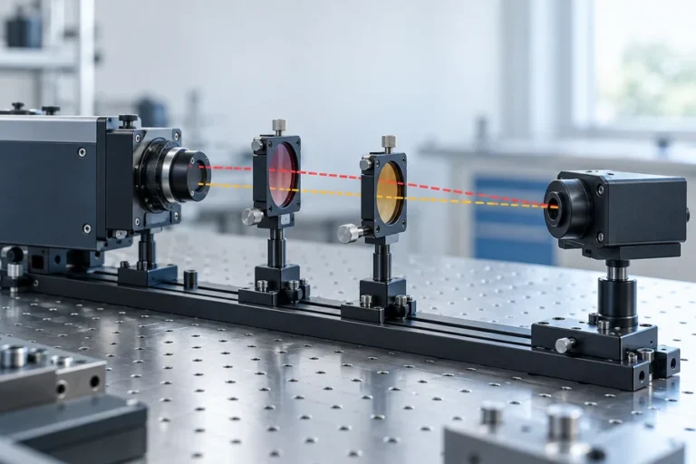
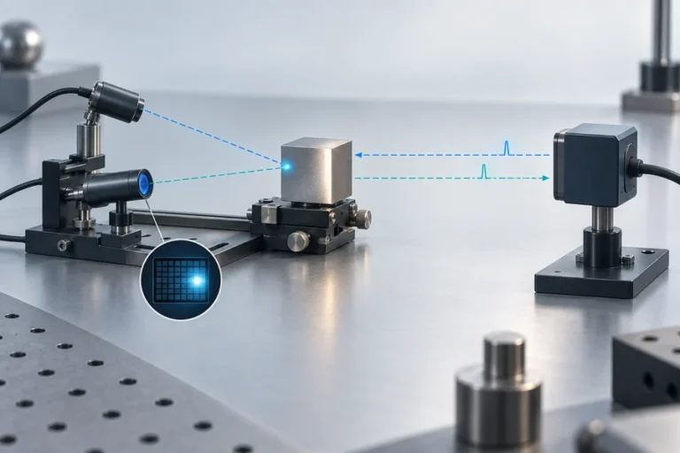



Laser rangefinder accuracy is a system result, not a single number detached from target, distance, environment, and test method. When a specification states ±1 m, it describes a permitted deviation under stated conditions. It does not mean every field result will land exactly one meter from the reference, nor does it identify every contributor to the observed error.
Lumexis develops laser rangefinder modules for civil, industrial, and research applications. This guide explains how to read an accuracy claim and turn it into a meaningful OEM validation plan.

Laser rangefinder accuracy begins with the measurement chain
In a time-of-flight system, distance is derived from the travel time of light to a target and back. The speed of light in vacuum is fixed by the SI definition, but real measurements depend on how reliably the instrument establishes a transmit reference, detects a return, and processes that return into a time estimate.
For that reason, a range value is influenced by the whole chain: optical emission, target response, receiver behavior, timing electronics, signal processing, calibration, and mechanical alignment. The fundamental principle is explained in our time-of-flight distance measurement guide.
What ±1 m normally communicates
An accuracy statement is commonly an allowable error band around a reference distance when tested according to specified conditions. It should be read alongside the range interval, target characteristics, ambient conditions, update behavior, temperature conditions, and any averaging or filtering used during the test.
The important buyer question is not just “what is the number?” It is “under what conditions was it established, and do those conditions represent our use case?” A suitable module for a controlled infrastructure measurement may need a different validation plan from one used in a moving industrial assembly.
Separate bias, repeatability, and resolution
Three terms are often mixed together:
| Term | Practical meaning |
|---|---|
| Bias | A consistent offset from a trusted reference |
| Repeatability | How tightly repeated results cluster under the same conditions |
| Resolution | The smallest displayed or reported increment |
A system can report small increments without having low overall error. It can also be very repeatable while consistently offset from the reference. Review all three when defining an acceptance test.
What changes real-world accuracy
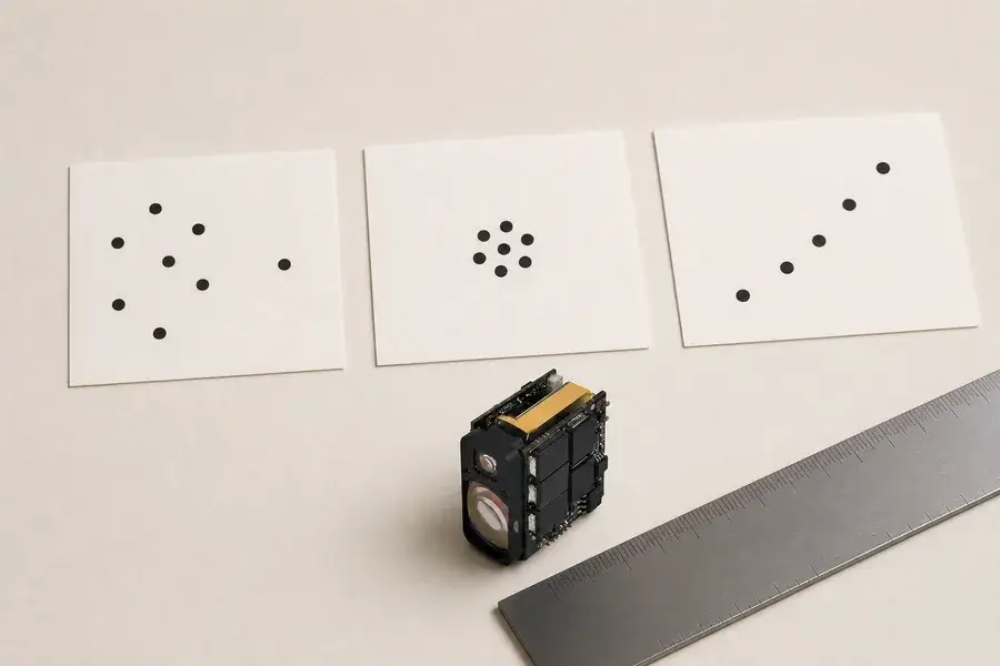
The returned optical signal changes with target material, surface geometry, distance, and ambient conditions. Receiver noise and timing jitter can affect the estimated return time. Temperature and supply conditions can change the behavior of the optical and electronic chain. Mechanical alignment and the integration window may alter the effective optical path.
These effects interact, so a single correction based on one target is rarely enough. Build a test matrix that covers the target types, distance bands, temperatures, and enclosure states that matter to the finished instrument. If the product uses a protective window, include it from the start; our guide to optical crosstalk in rangefinder integration explains why.
Turn the specification into an acceptance plan
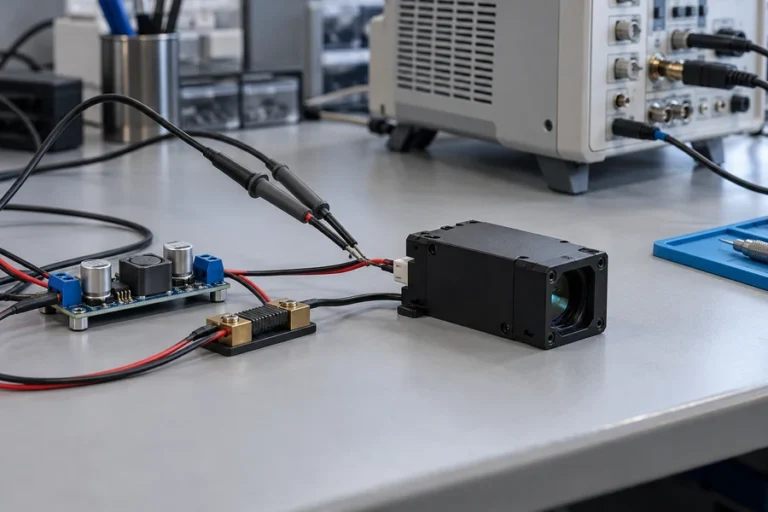
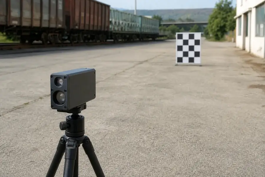
Use a traceable reference distance and define the target, geometry, measurement count, warm-up state, and allowed error before collecting data. Keep raw data, calculated statistics, and configuration information together. Record any invalid readings rather than silently removing them.
A practical plan can include:
- reference checks at several application-relevant distances;
- repeated measurements at each point to observe spread and bias;
- target surfaces representative of the deployment;
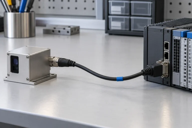
- final enclosure, cable, power, and host software;
- a retest after mechanical or optical changes.
Improve confidence, not just a headline value
Accuracy improves through controlled optics, stable timing, suitable return-signal processing, calibration where appropriate, and careful integration. The most valuable outcome for an OEM is a documented performance envelope that the production system can reproduce.
For a complete module evaluation workflow, read how to read a laser rangefinder module datasheet. Lumexis can help translate application conditions into module selection, an integration plan, and a production-relevant validation method. Contact us to discuss your requirements.
Define what happens when a reading is not usable
An acceptance plan should include more than nominal measurements. Define how the host identifies an invalid result, what is logged, whether a repeat is allowed, and when the application should hold or reject the reading. These rules turn an accuracy target into dependable system behavior.
Technical reading: NIST’s SI definition of the meter fixes the speed of light in vacuum used by time-of-flight ranging; the implementation error budget remains a system engineering task.
FAQ
Does ±1 m mean every measurement will be exactly within one meter?
It indicates an allowed deviation under the conditions used for that specification. The final application should verify the relevant distance range, target properties, environment, and integration state rather than treating the figure as universal.
Is high resolution the same as high accuracy?
No. Resolution is the smallest reported step. Accuracy concerns closeness to a reference, and repeatability concerns result spread. A system may show fine increments while still having bias or variable results.
Why can target material affect a time-of-flight result?
Target material and geometry change the returned optical signal. That can affect the receiver’s estimated arrival time, particularly when return strength and waveform shape differ. Test representative targets instead of one convenient reference only.
Should accuracy be checked after installation?
Yes. The window, alignment, supply, cable, host timing, and enclosure can all change the realized system behavior. Validate the production-representative assembly at application-relevant conditions.