
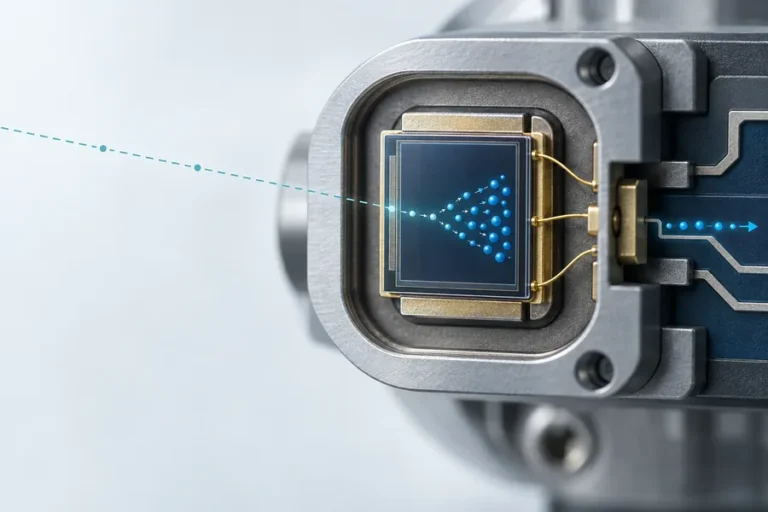








A serial link can return plausible bytes on a short bench cable and still create problems once it reaches the finished instrument. The missing work is often not enabling a port. It is agreeing on the electrical boundary, message contract, timing behaviour, recovery path, and acceptance evidence before the design is frozen.
A laser rangefinder module UART interface carries framed asynchronous serial data between a module and a host. It does not, by itself, define the module’s pinout, permitted logic levels, connector, command grammar, measurement behaviour, or timeout rules. For reliable OEM integration, confirm those details for the released module variant, then validate them in the installed system.
Lumexis develops and manufactures laser rangefinder modules for civil, industrial, and scientific systems. This guide turns UART integration into a controlled engineering workflow rather than a late-stage wiring exercise.
A laser rangefinder module UART is a boundary, not a full specification
UART is asynchronous serial communication. The endpoints use framing rather than a shared clock, and both sides need compatible transfer settings such as bit rate, data format, and any parity arrangement. Texas Instruments’ UART application material uses start and stop framing to explain that boundary; it is a useful foundation, not a protocol for a specific Lumexis module.
Treat the released module documentation as the contract. Confirm the applicable supply requirements, I/O compatibility, connector orientation, serial settings, command framing, integrity rule, startup state, and reporting behaviour. A host can display plausible characters and still be wrong if its assumptions do not match the variant it is connected to.
The same discipline applies when you read a laser rangefinder module datasheet. A UART label is not a substitute for the electrical and protocol definitions around it. Do not infer a voltage level, default frame, or command set from connector size, a previous sample, or another supplier’s module.
Freeze an interface-control record before firmware work
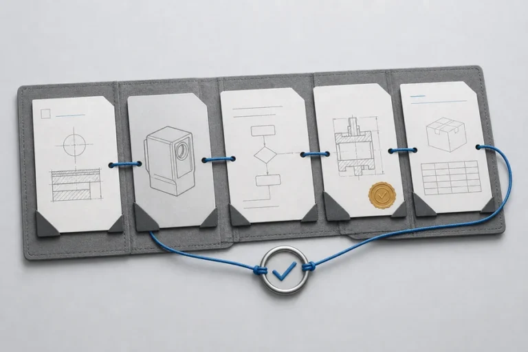
Before firmware work, create a concise interface-control record shared by electrical, firmware, systems, and test owners. Its job is to make each assumption visible early enough to correct it cheaply. It should identify the module variant and document revision, then point back to the released source for every electrical or protocol value.
| Item | What to record |
|---|---|
| Signal direction | Module-to-host transmit/receive roles, common reference, and any documented control lines |
| Logic domain | Confirm compatibility for the exact module variant; do not assume it from the word UART |
| Power-up state | Output behaviour before the host is ready |
| Cable and connector | Length, shielding plan, strain relief, and pin numbering |
| Protection | ESD and transient strategy at the system boundary |
| Recovery | Host behaviour after a timeout, malformed frame, reset, or restart |
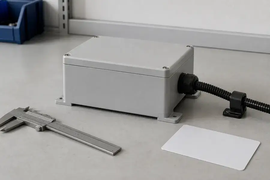
If the module sits outside the main board, review the cable path, reference path, shielding plan, enclosure boundary, and protection placement as a system. Those choices belong in the record because they affect the conditions under which the communication design will be verified.
Build the driver around frame integrity and recovery
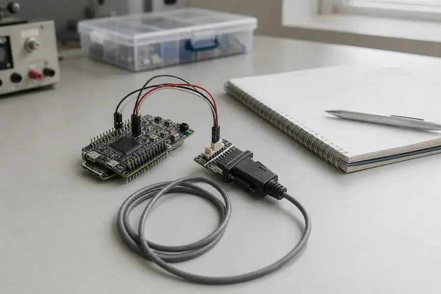
A robust driver separates byte transport from measurement logic. The transport layer collects bytes, identifies a complete documented frame, and rejects an invalid one. The measurement layer decides when to request or accept a result, how long to wait, and how a valid, invalid, or unavailable result is represented to the rest of the instrument.
Document these questions explicitly:
- Is the host polling for a single result, starting a continuous stream, or receiving data on an event?
- Which bytes identify a frame boundary and how is length determined?
- Is there a checksum or other integrity field?
- What does a timeout, out-of-range indication, or invalid result look like?
- Can configuration commands and measurement commands arrive concurrently?
Use a receive buffer that tolerates partial frames and extra bytes. After a bad frame, resynchronize from the documented structure rather than treating the next byte as a guaranteed new message. During development, raw-frame logging can expose integration faults; in the finished instrument, keep diagnostics deliberate enough that they do not change the behaviour being observed.
The UART transport is not the ranging algorithm. The host receives a documented representation of a measurement result; the optical and signal-processing conditions remain part of the module and system design. Our overview of how a laser rangefinder measures distance provides that separate context.
Budget timing across the measurement cycle
The serial link is only one part of the observable cycle. A completed interaction can include command reception, internal measurement and processing, response transmission, host parsing, and application handling. Define the interface requirement in those terms: expected command-to-response behaviour, continuous-output interval when applicable, timeout margin, and restart behaviour.
Validate that behaviour on target hardware at startup, normal operation, and expected processor load. A link that works with an unloaded development board can still suffer queueing, buffer, power, or scheduling problems in the final product. If a result triggers a separate subsystem, pass it through a defined handoff rather than allowing a parser fault to block the measurement path.
For broader application context, see Lumexis’ laser-ranging solutions. The right integration choice depends on the whole instrument, not simply on a familiar serial label.
Validate the installed system, not only the short bench cable
Validate communication and ranging separately, then together. First use a controlled host or test firmware to verify framing and recovery. Next exercise the documented measurement behaviour against suitable controlled targets. Finally repeat the work with the final cable, power supply, enclosure, processor load, and operating sequence.
Useful acceptance checks include repeatable startup, correct command acknowledgement, valid-frame handling, response timing, recovery after a disconnected cable, and consistent application-side handling of invalid measurements. The acceptance method should state the module and firmware revisions, host configuration, cable assembly, test conditions, and pass/fail handling before the test begins.
Preserve the record from sample through production
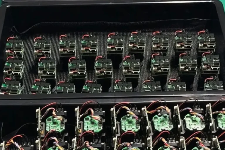
Keep the module part revision, firmware revision, serial configuration, cable drawing, host build, and test result together. This makes later troubleshooting faster because a result can be compared with the configuration that produced it. During production, the same record provides a clear handoff between electrical test, firmware release, and final equipment verification.
This is also where a supplier relationship becomes practical. Lumexis’ technology platform combines optical and optomechanical design, electronics and firmware, test-method development, thermal design, and weak-signal ranging algorithms. Our applications engineers can help move from a released interface requirement to an integration and validation plan; that support continues through engineering services when a project needs custom work or troubleshooting.
When to ask Lumexis to review the interface
UART can be a sensible option for a nearby point-to-point controller when the documented electrical and protocol conditions fit the product. If the host is remote, the cable route is electrically demanding, or the equipment needs a different topology, discuss the whole interface requirement rather than stretching a local design beyond its intended boundary.
We work from the interface requirement back to the module integration plan: electrical constraints, measurement cadence, enclosure, and verification. Lumexis manufactures its laser sources and modules through a vertically integrated process at a 14,000-square-metre Taizhou manufacturing base, with engineering and commercial support in Wuxi. For the applicable laser rangefinder module product family, our team can help assess standard options, custom configurations, and suitable private-label programmes. Standard products can ship within three days when availability matters; custom-product timing should be confirmed against the project requirements.
FAQ
Does UART define the connector pinout?
No. UART describes an asynchronous serial signalling method; it does not prescribe a connector, pin order, voltage level, command set, or baud rate. Use the documentation for the exact module version and capture those details in the interface-control record.
Why does a UART link work on the bench but fail in the enclosure?
The installed cable, ground return, supply noise, connector contact, and processor load can differ materially from a short bench connection. Re-test with production-representative wiring and power conditions, and exercise restart and timeout recovery.
Should the host poll or use continuous output?
Choose the mode that matches the application timing and data ownership. Polling can simplify synchronization; continuous output can simplify periodic data collection. The right choice depends on documented module behaviour and the host’s ability to process every result.
What should firmware do with a malformed serial frame?
Discard it safely, resynchronize on the documented frame structure, count the event for diagnostics, and continue. Avoid treating a partially received message as a distance result or allowing a parser error to block the measurement loop.
Is UART always the right interface for a rangefinder module?
No. It can be appropriate for a nearby point-to-point host when the module documentation and installed electrical environment support it. Cable route, noise exposure, system topology, service needs, and required data behaviour may lead the project toward another documented interface arrangement.
References
- Texas Instruments, Implementation of a Software UART on TMS320C54x Using General-Purpose I/O Pins, accessed 2026-08-03.
- Texas Instruments, Implementing a Software UART on the TMS320C54x with the McBSP and DMA, accessed 2026-08-03.
- Texas Instruments, Launchpad-Based MSP430 UART BSL Interface, accessed 2026-08-03.
Tell our engineering team the module variant, host interface constraints, protocol expectation, cable or enclosure conditions, and validation stage. We can recommend a suitable starting point, review a custom or private-label requirement, and involve an applications engineer before the interface becomes a production issue.