








Distance sensing is often specified as a single range figure. That number is not enough to predict how a finished instrument will behave when the target changes, ambient light rises, the enclosure warms up, or a host controller asks for an answer at a particular moment.
For OEM teams, the useful question is not simply whether a sensor uses ToF. It is which ToF method it uses, what the received signal represents, and which electrical, optical, and test conditions define an acceptable measurement.
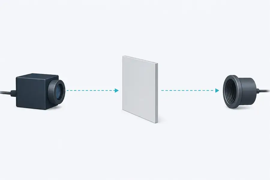
Time of flight distance measurement calculates range from the travel time of an emitted optical signal and its reflected return. In a direct system, the electronics measure the round-trip delay of a pulse. In an indirectly measured system, they infer that delay from the phase shift of a modulated signal. Both methods need controlled optics, timing, signal processing, and application-specific validation.
How time of flight distance measurement works
The basic relationship is straightforward: distance equals the propagation speed multiplied by the measured round-trip time, divided by two. The division by two accounts for the outgoing and returning path. For light in vacuum, the defined speed is 299,792,458 meters per second, so small timing errors can become meaningful distance errors quickly.
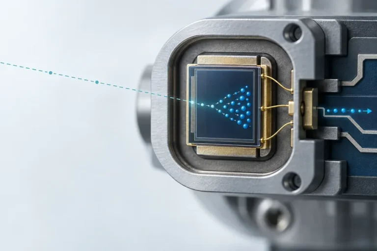
In a practical optical system, the clock is only one part of the result. A transmitter creates a controlled optical signal, transmit optics direct it toward the target, and receive optics collect a small returned fraction. A detector and analog front end convert that return into an electrical signal, then timing or demodulation logic estimates the delay before firmware applies validity rules and reports a distance.
Target reflectance, area, angle, motion, optical alignment, divergence, receiver aperture, background illumination, temperature, and the acceptance algorithm can all affect the result. That is why a time-of-flight specification must be paired with a test condition, not read as a universal promise.
Direct and indirect ToF measure different signals
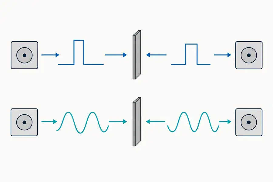
Direct ToF measures the elapsed time between an emitted pulse and the detected return. In a single-point laser ranging instrument, that can mean timing a short optical pulse against a reference event and deciding whether the returned signal meets the system’s detection criteria. Pulse width, detector response, clock stability, threshold behavior, and signal-to-noise ratio all influence the final estimate.
Indirect ToF uses a continuously modulated optical signal. Instead of timing one pulse edge, the system measures the phase relationship between transmitted and received modulation. The phase delay corresponds to propagation time, but the interpretation depends on modulation frequency, demodulation method, phase unwrapping, and calibration. Phase ambiguity becomes a design constraint because repeated phase cycles can represent more than one possible distance.
Neither label determines system quality by itself. Direct timing can suit a wide range of ranging architectures, while phase-based measurement can be useful where its ambiguity range and calibration requirements fit the job. The correct choice starts with target conditions, working distance, update behavior, allowable uncertainty, optical geometry, and the integration burden on the host.
Where measurement error enters the signal chain
The range equation hides the real engineering work. The return may weaken because of target reflectance, angular orientation, spot placement, atmospheric transmission, a cover window, or background light. It may also be distorted by multipath reflections, receiver saturation, electronic noise, timing jitter, temperature drift, or a reporting threshold that is not tuned to the intended target.
Use a complete signal-chain review instead of isolating one component. For the optical path, specify the target, its expected surface behavior, the beam footprint, the receive field of view, and the enclosure window. For electronics, specify supply behavior, trigger reference, timebase stability, receiver bandwidth, host timing, and the way invalid or low-confidence returns are handled.
Calibration cannot be an afterthought. Establish which distance references, target materials, temperatures, and orientations are used during development and production. Then distinguish repeatability at one controlled condition from accuracy across the application envelope. A well-designed test plan makes those differences visible before a module is committed to a host platform.
For a broader view of the ranging core itself, see our guide to laser rangefinder modules. It explains where the module boundary sits relative to the enclosure, controller, and final product-level verification.
OEM integration checks before design freeze
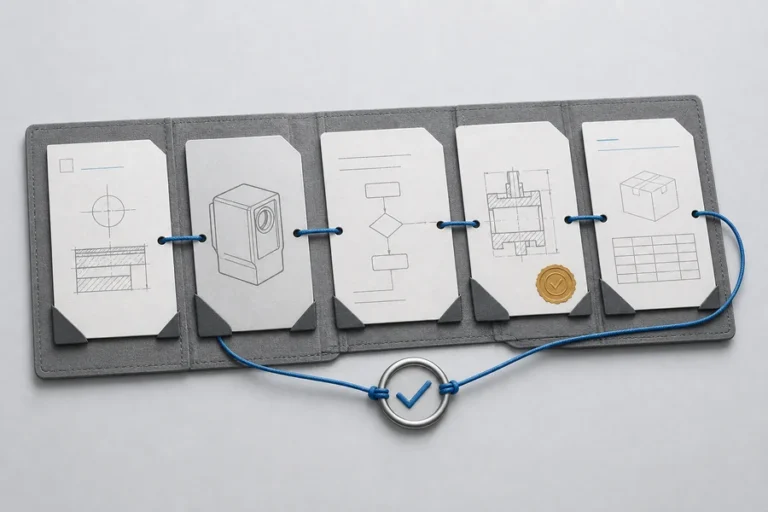
The fastest way to create a late-stage ranging problem is to treat the module as a black box. Start by documenting the measurement job in terms the optical, mechanical, electrical, and firmware teams can share.
| Review area | Questions to resolve |
|---|---|
| Target condition | What material, size, reflectance, angle, and range interval define a valid reading? |
| Optical integration | Where is the optical-axis reference, and how will the window, mounting, contamination control, and alignment tolerance affect it? |
| Electrical timing | What supply limits, trigger reference, interface timing, data frames, and error states must the module and host agree on? |
| Thermal and mechanical fit | How is heat removed, which datums constrain the module, and what test access remains after enclosure assembly? |
| Acceptance test | Which targets, distances, temperatures, sample counts, and pass criteria will prove the finished instrument? |
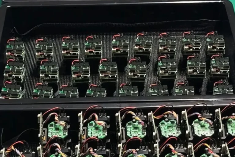
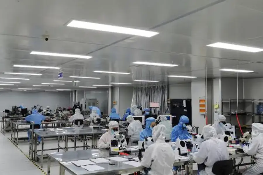
At Lumexis, we approach range measurement as a system integration problem. Our teams design and manufacture laser sources and ranging modules for civil, industrial, and scientific instruments, combining optical and optomechanical design, electronics and firmware, thermal management, test-method development, and weak-signal ranging algorithms. Incoming inspection, chip test, assembly, coupling and alignment, aging screening, and final performance testing support a repeatable production flow.
Choosing the right evidence from a supplier
When evaluating a time-of-flight module, ask to see the operating point behind each relevant result. A useful data package ties the measurement to target material and geometry, range, ambient condition, module temperature, supply condition, update mode, and the rule used to accept a return. This prevents a bench result from being mistaken for an application result.
Reliability evidence matters too. Ask how optical alignment is protected through assembly, how temperature exposure is evaluated, how early-life screening is handled, and how product or process changes are controlled. These details affect field risk, production yield, and the cost of resolving an issue after the host design is frozen.
Our technology capabilities describe the engineering disciplines behind that review, while our services team can help convert your target and interface conditions into a workable evaluation plan. For application context, explore the civil and industrial systems on our applications page.
FAQ
What is the formula for time-of-flight distance measurement?
For a reflected optical signal, time of flight distance measurement uses the simplified relationship distance = c × t ÷ 2, where c is the relevant propagation speed and t is the measured round-trip time. In a finished instrument, the timing estimate must also account for the measurement architecture, calibration method, optical path, and conditions used to validate the result.
What is the difference between direct and indirect ToF?
Direct ToF estimates distance from the measured delay of a returned light pulse. Indirect ToF estimates delay from the phase shift between transmitted and received modulated light. They therefore put different requirements on timing, modulation, demodulation, ambiguity handling, calibration, and the conditions under which a return is accepted.
What affects a time-of-flight sensor’s distance reading?
The result can change with target reflectance, target angle and size, signal strength, background illumination, optical alignment, receiver behavior, temperature, electrical noise, and the signal-processing rule. Ask for the complete test condition so you can judge whether a reported result maps to the finished instrument’s use case.
Can a time-of-flight module be used without system-level testing?
No. The host enclosure, optical window, mounting, thermal path, supply, data interface, and target environment can all change the measurement. Module-level evidence is an important starting point, but final validation must be performed on the integrated civil, industrial, or scientific instrument.
How should an OEM compare ToF module suppliers?
Compare complete evidence packages rather than headline range alone. Look for traceable operating conditions, clear electrical and mechanical interfaces, relevant screening and temperature evidence, transparent acceptance criteria, and engineering support that can address the host system rather than only the module in isolation.
If you are defining a ToF-based instrument for civil, industrial, or scientific measurement, contact our engineers with the target condition, distance range, enclosure constraints, power budget, and host interface. We will help turn those inputs into a practical module evaluation plan.
References
1. National Institute of Standards and Technology, “Definitions of SI Base Units”. Accessed August 2, 2026. 2. Thomas Brand, Analog Devices, “Time of Flight System for Distance Measurement and Object Detection”. Accessed August 2, 2026. 3. Radu Horaud, Miles Hansard, Georgios Evangelidis, and Clement Ménier, “An Overview of Depth Cameras and Range Scanners Based on Time-of-Flight Technologies”. Accessed August 2, 2026. 4. Piotr Jaworski et al., “Methods of Precise Distance Measurements for Laser Rangefinders with Digital Acquisition of Signals”. Accessed August 2, 2026.