



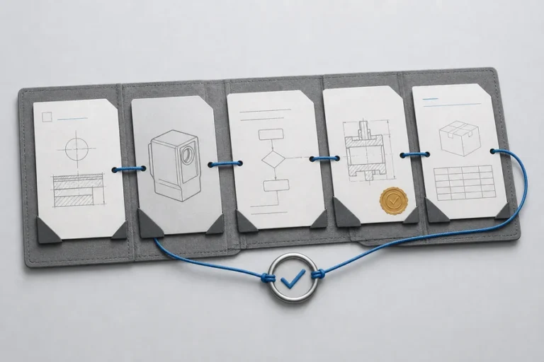





Distance is easy to describe and hard to measure reliably once a sensor leaves the bench. Target surface, ambient light, mounting tolerance, host power, and the way the result is reported can all change whether a reading is useful in an industrial or scientific instrument.
That is why OEM teams need more than a headline range. They need to understand what the ranging engine contains, which conditions its result depends on, and where the module ends and the host system begins.
A laser rangefinder module is a compact optoelectronic assembly that measures distance by transmitting laser light toward a target, detecting the returned signal, and converting the measured delay or another ranging signal into a digital result. It supplies the core ranging function for a larger civil, industrial, or scientific instrument; the final system supplies the enclosure, user interface, power architecture, and application-specific validation.
What is a laser rangefinder module for OEM integration?
The word “module” matters. A finished instrument is a complete product with its own housing, controls, display or host connection, and validation for its intended use. A laser rangefinder module is the subsystem that gives that product its distance-measurement capability.
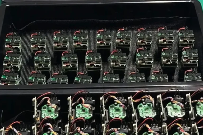
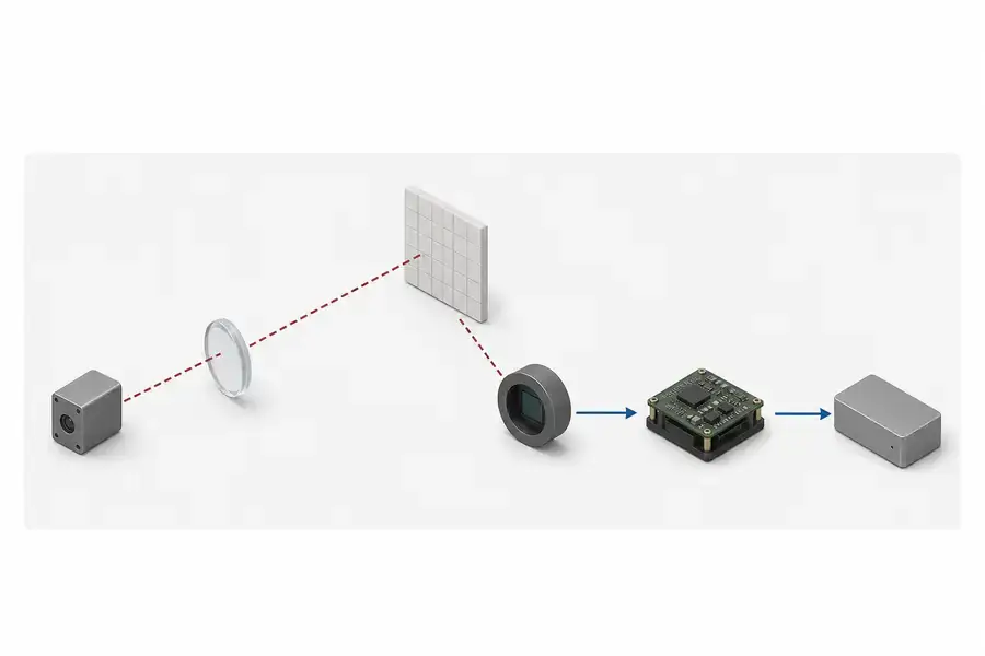
The exact architecture varies, but an OEM module commonly brings together a laser transmitter, transmit and receive optics, a photodetector or receiver chain, timing or signal-processing electronics, power conditioning, and a communication interface. The transmitter puts a controlled optical signal onto the target. The receiver collects a small fraction of the return, while electronics decide whether the return is valid and calculate the distance.
That division of work is useful for system design. Your team can select the enclosure, display, controller, mounting, and data workflow around a ranging core that has already been designed and qualified as a unit. The interfaces still need engineering attention: optical-axis location, heat path, supply behavior, connector access, message timing, and the conditions under which a reading is reported.
How a module measures distance
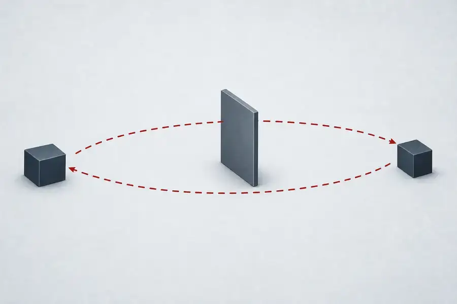
Many laser rangefinder modules use direct time of flight. The module emits a short optical pulse, detects the reflected return, measures the round-trip interval, and calculates distance from the known propagation speed. In its simplified form, the relationship is distance = c × time ÷ 2, where c is the speed of light in vacuum and the division by two accounts for the outbound and return path.
The formula is only the start of the engineering problem. A real return signal depends on target reflectance, target area and angle, working distance, atmospheric conditions, transmitter divergence, receiver aperture, filtering, detector behavior, and the measurement algorithm. The National Institute of Standards and Technology defines the speed of light in vacuum as exactly 299,792,458 meters per second; a practical range measurement still has to manage the uncertainty and signal conditions of the complete optical system.
Not every laser distance measurement product uses the same method. Some short-range sensors use phase-based techniques, while pulsed systems work from a measured transit interval. The selection question is not which label sounds more precise. It is whether the chosen architecture, target condition, update rate, and acceptance method match the instrument you are building.
The signal path matters as much as the laser source
It is tempting to think of a rangefinder as a source plus a timer. In practice, a usable result requires a chain of linked decisions. The transmit path shapes and directs the outgoing pulse. The target changes the amount of light returned. The receive path collects and filters that return. The detector and electronics convert it into timing information, and the algorithm decides whether to report a distance.
Each handoff can become an integration constraint. A narrow transmitted divergence can change how much energy reaches a distant target, but it can also increase sensitivity to pointing and mounting stability. A receiver with a wider field of view may see more of a moving target, yet it can also admit more background light. A result that looks stable under one target and ambient condition may need a different threshold or measurement mode in the finished instrument.
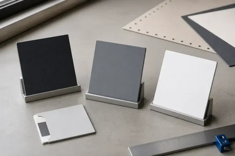
For this reason, compare range claims only when their test conditions are comparable. Ask for target material, reflectance, target size, angle, ambient illumination, module temperature, measurement mode, supply condition, and the rule used to call a reading valid. Our technology approach starts with these interfaces because they determine whether a module can become a dependable system rather than a promising bench result.
What the module does not solve for you
The module is not the whole accuracy budget. The final product can add alignment offsets, cover-window losses and reflections, enclosure heating, supply noise, communication latency, target variation, and software filtering. A good module creates a known starting point; it does not remove the need for end-of-line validation in the host instrument.
Mechanical integration is often where surprises appear. Before an enclosure is fixed, define the mounting datums, optical-axis reference, keep-out zones, connector bend radius, cooling path, and access needed for production test. Before firmware is fixed, define logic levels, data frames, command timing, error behavior, startup conditions, and the meaning of every status field. Our engineering services can help turn those questions into an evaluation plan.
Also separate a source-level specification from a system-level result. A wavelength or compact package does not establish the classification, output behavior, or field performance of the finished instrument. Validate the final assembly against its own intended operating conditions and supported product evidence.
A practical checklist for OEM evaluation
Use the first review to make the module and host responsibilities explicit.
| Review area | Questions to resolve before design freeze |
|---|---|
| Target and range | What target material, size, reflectance, angle, and distance define success? |
| Optical integration | Where is the optical axis, and how will the window, mounting, and pointing tolerance affect the signal? |
| Electrical and data interface | What are the supply limits, peak behavior, connector details, frames, timing, and error states? |
| Thermal and mechanical fit | How is heat removed, what are the mounting datums, and what access is needed for test and service? |
| Verification | Which target conditions, temperatures, sample counts, and pass criteria will the finished instrument use? |
At Lumexis, our team designs and manufactures laser sources and ranging modules for measurement, sensing, industrial, and scientific systems. We combine optical and optomechanical design, electronics and firmware, thermal management, test-method development, and weak-signal ranging algorithms. In production, incoming inspection, chip test, assembly, coupling and alignment, burn-in or aging screening, and final performance testing help make reliability a design input rather than an afterthought.

Where modules fit in real instruments
Laser rangefinder modules can support industrial sensing, railway and infrastructure inspection, surveying instruments, scientific research equipment, and other civil measurement systems where an integrator needs distance data inside a larger product. The application sets the meaningful requirements: some programs prioritize working-distance coverage, others a compact envelope, target behavior, stable repeatability, host-interface simplicity, or production traceability.
The right conversation therefore begins with the measurement task, not a single brochure value. See the civil and industrial contexts on our applications page, then bring the target conditions and host constraints to the supplier discussion. That produces a clearer evaluation plan and reduces late changes to optics, mechanics, or firmware.
FAQ
What is a laser rangefinder module used for in an OEM instrument?
No. The module is the optoelectronic ranging core intended for integration into a larger instrument. The finished product adds the enclosure, power architecture, controller, user interface, application software, and product-level verification. Treat the module specification as one part of the finished instrument’s design record.
How does a laser rangefinder module calculate distance?
Many modules transmit a short pulse and measure the time until a reflected signal returns. The electronics use the round-trip interval to calculate distance. The actual result also depends on the target, optical geometry, ambient conditions, receiver chain, and the rule used to accept or reject a measurement.
What should I ask for besides maximum range?
Ask for the complete test condition: target material and reflectance, target size and angle, ambient illumination, temperature, supply condition, measurement mode, update rate, and acceptance rule. Also request the optical, mechanical, electrical, and communication details that determine host-system work.
Can one module be dropped into any enclosure?
Usually not without a defined integration plan. The enclosure can affect alignment, heat removal, optical-window behavior, connector access, and production testing. Establish mounting datums, optical-axis reference, clearance zones, thermal path, and test access before the enclosure is finalized.
What makes a module suitable for an OEM program?
Look for a clear interface definition, traceable test conditions, evidence relevant to the intended operating environment, and direct engineering support for integration questions. Consistency across temperature and time, production screening, and change-control discipline can matter as much as an individual headline specification.
If you are defining a civil, industrial, or scientific ranging instrument, contact our engineers with your target conditions, range, enclosure limits, power budget, and data interface. We will help turn them into a practical module evaluation plan.
References
1. National Institute of Standards and Technology, “Definitions of SI Base Units”. Accessed August 1, 2026. 2. Rüdiger Paschotta, “Laser Rangefinders”, RP Photonics Encyclopedia. Accessed August 1, 2026. 3. A. S. Dorrington et al., “An Overview of Depth Cameras and Range Scanners Based on Time-of-Flight Technologies”. Accessed August 1, 2026.