









A laser rangefinder module datasheet can look reassuringly complete while still leaving the integration team with the hard questions. A headline range, a compact outline drawing, and a short list of electrical values do not tell you whether the module will meet your target conditions, fit the enclosure, or behave consistently across production units.
That gap becomes expensive when assumptions surface after the mechanical design, host electronics, or acceptance test has already moved forward. The remedy is not a longer specification table. It is learning which values are conditional, which interfaces must be defined, and which evidence to request before a module is selected.
A laser rangefinder module datasheet should be read as a statement of performance under stated conditions, not as a universal promise. Start with the target, range, temperature, update-rate, and supply conditions behind each value; then check how optical, mechanical, electrical, and verification requirements connect to your actual system.
Read the laser rangefinder module datasheet in context
Most data sheets group values into optical, ranging, electrical, mechanical, environmental, and interface sections. That format is useful, but it can encourage an unhelpful habit: comparing one line from one supplier with a similar-looking line from another. A valid comparison starts only after the operating conditions and measurement method have been made common.
Laser ranging measures round-trip travel time, so the basic distance relationship is straightforward: distance is proportional to the measured time divided by two. The real result depends on the transmitted pulse, target, return signal, receiver, timing electronics, and processing chain. NIST’s explanation of the meter is a useful reminder that length and time are linked through the speed of light in vacuum; a field measurement still carries the practical limits of its optics and test setup.
When you compare a data sheet, make a small condition sheet beside it. Record the target material and size, reflectance, working distance, ambient illumination, atmospheric condition, module temperature, supply voltage, measurement mode, and repetition rate. If a value does not name its condition, treat it as a question for the supplier rather than a fixed design input.
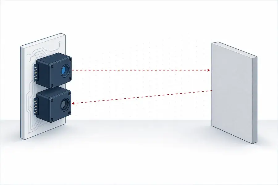
Typical time-of-flight concept. Dashed paths are conceptual and do not represent visible light.
Start with range, minimum distance, and target conditions
The maximum range line is usually the first one a buyer reads, but it is also the least portable number. Range changes with target reflectance, target area and orientation, optical aperture, divergence, atmosphere, receiver sensitivity, background light, and signal-processing settings. Two modules can each state a similar maximum range while being tested against very different targets or acceptance criteria.
Ask for the full target definition and the success rule. Does the value describe a single reading, a probability of valid readings, a filtered result, or a result after repeated attempts? Does it use a diffuse target, a structured target, or a reflector? Those details matter because the returned signal is a system outcome, not a property of the transmitter alone. RP Photonics’ rangefinder overview gives useful context on the interaction of emitted light, target return, and receiver performance.
Minimum range deserves equal attention. It may be limited by receiver recovery, optical overlap, timing architecture, signal processing, or a product-specific measurement mode. A module that is suitable for distant infrastructure inspection may not meet a short working-distance requirement, even when its accuracy line appears attractive.
Separate accuracy, resolution, and repeatability
These three entries answer different questions. Accuracy describes agreement with a reference under defined conditions. Resolution is the smallest displayed or reported increment. Repeatability describes how closely repeated readings agree when conditions are held stable. A data sheet may provide one of these values without establishing the others.
For an OEM program, ask whether accuracy is typical or guaranteed, how the reference distance was established, whether the result includes calibration uncertainty, and how the value changes over the required temperature range. A value written as a plus-or-minus distance should not be read as a complete system error budget. Mounting stability, optical-window effects, host timing, target behavior, and filtering can all add uncertainty after integration.
The most useful acceptance plan names the distance points, target types, temperature states, number of samples, and pass criterion. This avoids a common failure mode: a module meets a benign bench condition but the finished instrument is evaluated against a different target and environment.

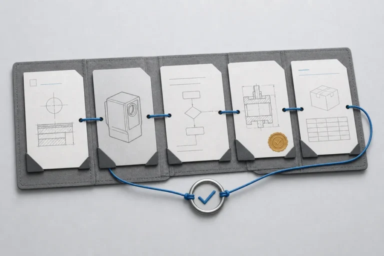
A selection review should connect each published value to its test condition and the corresponding host-system requirement.
Read optical values as a linked set
Wavelength, beam divergence, aperture, receiver field of view, and filtering are related system variables. A narrow divergence can concentrate transmitted energy on a distant target, while increasing sensitivity to alignment and pointing stability. Receiver field of view must be considered with the expected target motion, mounting tolerance, and the source geometry; it is not simply a larger-is-better number.
The data sheet should distinguish a nominal wavelength from an optical-safety classification. Wavelength alone does not determine the classification of a finished product. IEC 60825-1 addresses classification and requirements for laser products, while also noting that a component used in a subsequent product must be considered in the context of the final system. Review the applicable product evidence and intended use rather than inferring a claim from a wavelength label.
Where a beam divergence is listed, confirm the definition. Ask whether it is full angle or half angle, which axis it applies to, the operating condition, and the measurement method. Similarly, a receiver aperture diameter says little by itself without the transmission, detector, filtering, and target assumptions that determine the usable return.
Check power, interface, and timing before the enclosure is fixed
A single supply-voltage line does not replace an integration review. Confirm the input range, transient behavior, peak and average power conditions, connector and pin assignment, grounding approach, startup behavior, and fault response. For pulsed operation, distinguish average power from pulse-related demand; they create different constraints for the host supply and thermal design.
Interface information needs the same discipline. A label such as UART or TTL is only the beginning. Request logic levels, baud-rate or timing options, frame structure, command set, checksum behavior, message timing, diagnostic fields, and the behavior during a failed or ambiguous measurement. See how our technology team approaches system integration when you are turning those interface questions into a design review.
Mechanical data should identify mounting datums, tolerance references, cable exit, clearance zones, optical-axis location, heat path, and the allowed relationship between the module and any cover window. A compact module may be easy to place in CAD yet difficult to test, align, or service if these interfaces are not defined early.

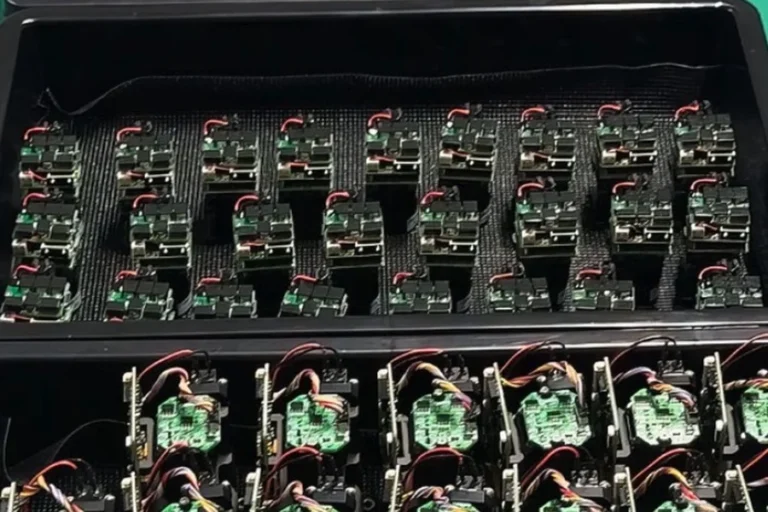
Controlled assembly and verification are part of the evidence behind a production-ready module, not an afterthought.
Turn environmental lines into a qualification plan
Operating-temperature and storage-temperature ranges are not interchangeable. The former should relate to functional performance at specified conditions; the latter may only describe survival. Ask whether a listed range applies to every function, whether warm-up is needed, and whether performance has been checked at the thermal extremes.
Other environmental statements also need a method. Vibration, contamination, humidity, or thermal-cycling requirements should identify the test profile, the pre- and post-test measurements, and the acceptance criterion. This is where a good supplier conversation often adds more value than another column in the comparison table.
At Lumexis, we build reliability into the production flow through incoming inspection, chip test, assembly, fiber coupling and alignment, burn-in or aging screening, and final performance testing as appropriate to the product and program. We recommend matching the requested evidence to the actual application risk, then making that evidence part of the specification and change-control plan. Our services team can help structure that review.
A practical data-sheet comparison checklist
Use this table to turn a brochure-level comparison into an engineering decision.
| Data-sheet entry | What to ask for | Integration decision it supports |
|---|---|---|
| Maximum and minimum range | Target, reflectance, area, atmosphere, reading rule, measurement mode | Whether the stated range matches the real task |
| Accuracy and resolution | Reference method, temperature, typical or guaranteed status, sample basis | Error budget and acceptance-test design |
| Divergence and receiver field of view | Full or half angle, axis, operating point, alignment tolerance | Optics, pointing, and mounting strategy |
| Supply and power | Peak and average demand, startup, transients, grounding | Host power and thermal design |
| Communication interface | Logic levels, protocol, timing, diagnostics, fault behavior | Firmware and electrical-interface scope |
| Mechanical outline | Datums, optical axis, heat path, window clearance, connector access | Enclosure, fixtures, and serviceability |
| Environmental and reliability data | Test profile, sample basis, pre/post criteria, records | Qualification scope and production risk |
FAQ
Is a laser rangefinder module datasheet enough to select a module?
It is a necessary starting point, not the full selection record. Use it to identify the operating conditions, interfaces, and verification evidence you need. Then compare modules against a written target and host-system requirement, not only against their headline range or package size.
Why can two modules with the same stated range behave differently?
They may use different targets, reflectance assumptions, optical designs, receiver settings, filtering, measurement modes, or success criteria. Compare the complete condition set and the test method. A range value without these details cannot establish equivalent delivered performance.
Does a smaller beam-divergence value always mean better range?
No. A smaller divergence can change energy placement on the target, but it can also increase alignment and pointing sensitivity. The right value depends on target size, working distance, mounting stability, optical aperture, and the intended measurement conditions.
What is the difference between accuracy and resolution in a rangefinder?
Accuracy is agreement with a reference distance under stated conditions. Resolution is the smallest reported increment. A module can display small increments without guaranteeing the same absolute agreement across targets, temperatures, and operating modes.
Which interface details should an OEM request?
Request the electrical levels, connector and pinout, data frame, timing, command behavior, error handling, diagnostics, startup sequence, and any configuration limits. These details determine how much firmware, electrical design, and production test work the host system will need.
If you are reviewing a module data sheet for an industrial or scientific ranging system, contact our engineers with the target conditions, enclosure constraints, electrical interface, and qualification needs. We will help turn them into a practical evaluation plan.
References
1. National Institute of Standards and Technology, “Meter”. Accessed July 30, 2026. 2. Rüdiger Paschotta, “Laser Rangefinders”, RP Photonics Encyclopedia. Accessed July 30, 2026. 3. International Electrotechnical Commission, “IEC 60825-1:2007 — Safety of laser products”. Accessed July 30, 2026.