

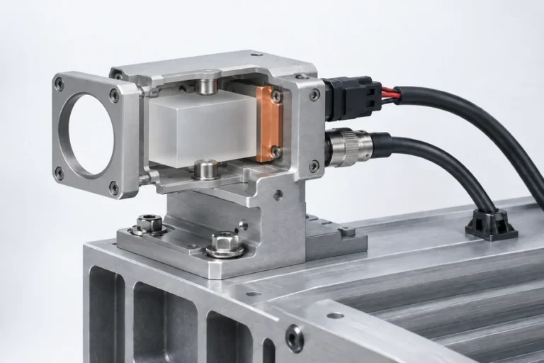
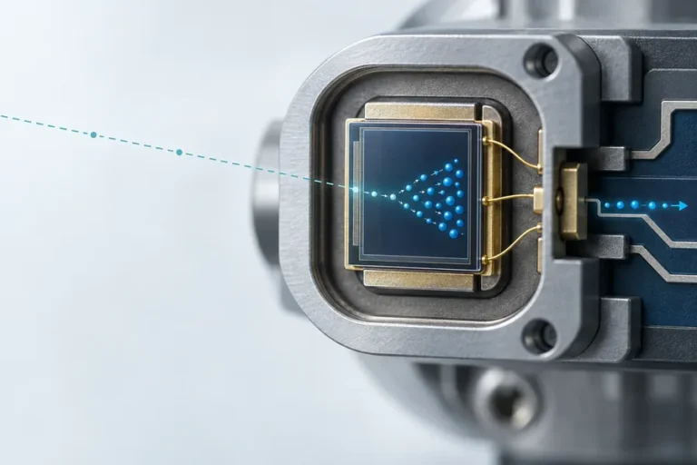




A laser rangefinder module can return clean distance data on an open bench and still become unreliable inside the host. A window clips the receive path, a cable pulls on the mount, a power rail dips during a measurement, or firmware treats an old response as a new one. These are integration failures, not isolated component failures.
Laser rangefinder module integration works when the OEM controls nine design gates: the target requirement, optical path, mechanical datum, thermal path, power rail, electrical link, firmware contract, system verification, and production handoff. Each gate needs an owner, a defined configuration, and objective evidence before the design moves forward.
Start with an interface contract, not a part number
The first integration document should describe what crosses the boundary between the module and the host. That boundary is wider than a connector. NASA’s product-integration guidance treats mechanical, thermal, electrical, data, and logical interactions as interfaces, including the needs of assembly, maintenance, and testing. The same system logic applies to an embedded ranging channel.
Write the host requirement before selecting or freezing a module. If the team is still comparing architectures, use our laser rangefinder module selection framework to separate application needs from brochure values. Then use the current laser rangefinder module datasheet guide to turn each supplier line into a condition, method, and integration decision.
| Design gate | Freeze before detailed design | Evidence needed to pass |
|---|---|---|
| 1. Target and decision | Target class, distance bands, scene conditions, cadence, success rule | Written use cases and acceptance cases |
| 2. Optical path | Window, clear apertures, divergence, receiver field, stray-return controls | Ray/clearance review and enclosed-system test |
| 3. Mechanical datum | Mounting references, tolerance stack, torque, cable strain, service access | Drawing review, fit check, and repeatability check |
| 4. Thermal path | Heat source, conductive path, warm-up state, alignment drift budget | Thermal analysis and hot/cold functional evidence |
| 5. Power rail | Input range, dynamic demand, startup, grounding, fault behavior | Rail capture under the real measurement cycle |
| 6. Electrical link | Logic levels, transceiver, cable, return path, termination | Link test in the final cable and noise environment |
| 7. Firmware contract | Commands, timing, validity, retries, diagnostics, versioning | Protocol tests including fault and stale-data cases |
| 8. System verification | Requirement IDs, methods, configurations, pass criteria | Requirement-to-evidence matrix and test records |
| 9. Production handoff | Controlled files, fixtures, reference units, logs, change rules | Repeatable build and end-of-line release package |
The table is not a sequence that one engineer completes alone. It is a contract among optical, mechanical, electrical, firmware, validation, manufacturing, and supplier teams. An unresolved assumption in one gate should remain visible because it can invalidate a decision elsewhere.
Gate 1: Define the target and the decision the host must make
Do not begin with “we need a 5 km module.” Begin with the target and what the host must decide about it. Record the target’s approximate size and surface, minimum and normal distance, farthest required distance, expected background, visibility, platform motion, update rate, and the consequence of a missed or ambiguous return.
Also define what counts as a valid result. Does the host need one confirmed distance, continuous updates, a first or last return, or an explicit no-return state? How old can a result be before the host rejects it? A technically correct distance can still be unusable if it arrives too late, belongs to the wrong pointing state, or lacks a confidence or fault indication.
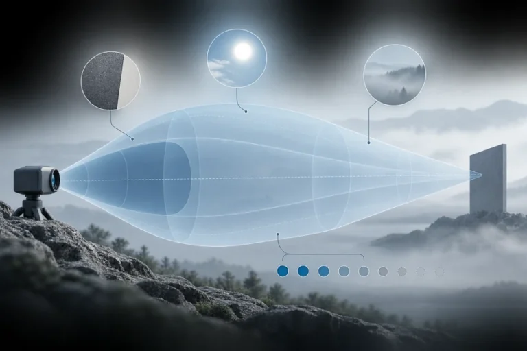
This target model becomes the common input to module selection, beam geometry, receiver behavior, firmware, and validation. It also prevents a maximum-range claim measured on one target under one condition from becoming an unconditional system requirement. Our guide to laser rangefinder maximum range explains why target, aperture, atmosphere, alignment, background, and acceptance logic remain coupled.
Gates 2–4: Control optics, mechanics, and heat as one stack
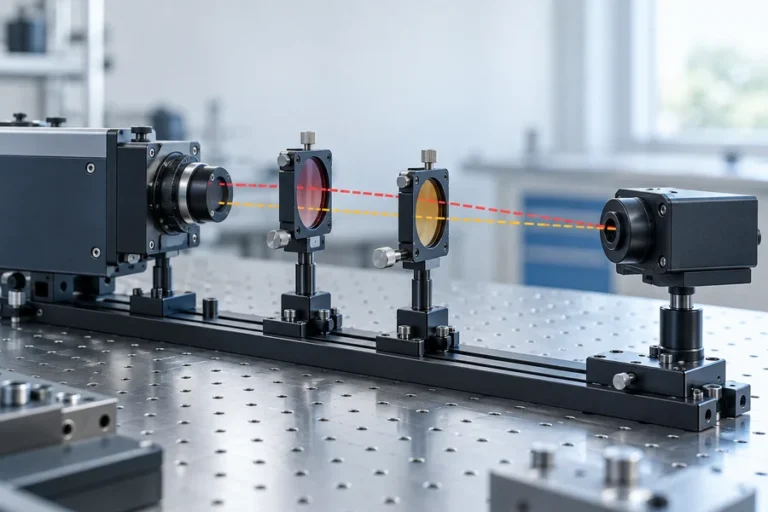
The rangefinder does not look through an abstract opening. It looks through a window, aperture, gasket, bezel, and tolerance stack that belong to the host. Review the transmitted beam and the receiver acceptance region across manufacturing tolerance, not only along their nominal centerlines.
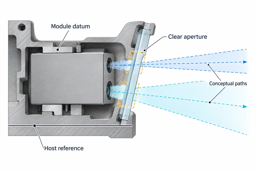
Treat the front window as an optical component
Confirm transmission over the actual source and receiver bands, coating behavior at the intended incidence angles, clear aperture, wedge or tilt, surface quality, contamination exposure, and how internal reflections are kept away from the receiver. A material name alone does not answer those questions. Window mounting stress and seal geometry can also change the optical relationship after assembly.
Leave margin around both paths for part, bracket, and assembly variation. A window frame, adhesive bead, screw head, cable, or neighboring optic may sit outside the nominal ray in CAD yet enter the real clearance envelope. For the return-path failure modes and diagnostic order, see our guide to optical crosstalk in rangefinder integration.
Build boresight from explicit datums
Choose the governing host reference: a mechanical datum, an imaging-axis reference, or another calibrated line of sight. Then define how the module datum, window, bracket, enclosure, and any adjacent sensor relate to it. The mount should seat repeatably without using cable force or fastener bending as an alignment method.
Document the torque sequence, allowed shims or adjustments, adhesive cure condition if applicable, and service removal process. Alignment should be checked after final assembly and at a realistic operating state. A cold bench check cannot reveal every shift caused by enclosure preload, cable strain, or the warm-state temperature field.
Give heat a deliberate route
A compact module may reject heat mainly through a mounting surface. If that contact is small, uneven, insulated by a finish, or interrupted by a soft bracket, the internal temperature can move even when ambient temperature is unchanged. Define the conductive path from module to bracket, bracket to chassis, and chassis to the external environment.
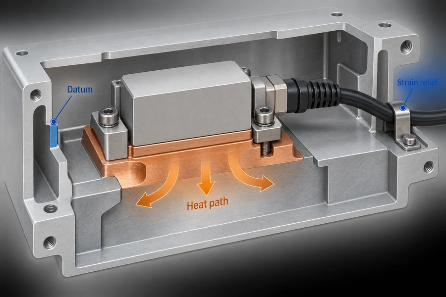
Thermal design and boresight belong in the same review. Materials expand, joints settle, and nearby heat sources create gradients. Verify ranging and alignment after warm-up, across the intended operating envelope, and after the relevant mechanical stresses. Do not assume that survival at a temperature extreme proves measurement performance there.
Gate 5: Qualify the power rail under a real measurement cycle
A nominal supply value is only the starting point. Request the allowed input range, startup sequence, inrush behavior, peak and average demand, pulse or burst timing, undervoltage response, fault recovery, and grounding expectations. Measure these behaviors with the actual cable, connector, regulator, and host loads.
Dynamic testing matters because a supply can look correct on a multimeter while showing a short dip, overshoot, or ringing event during a measurement. Analog Devices’ guidance on line and load transient testing explains how abrupt load changes expose regulation and recovery behavior that steady-state checks miss. Capture the rail at the module input while commanding the real operating cadence, then repeat with other noisy host loads active.
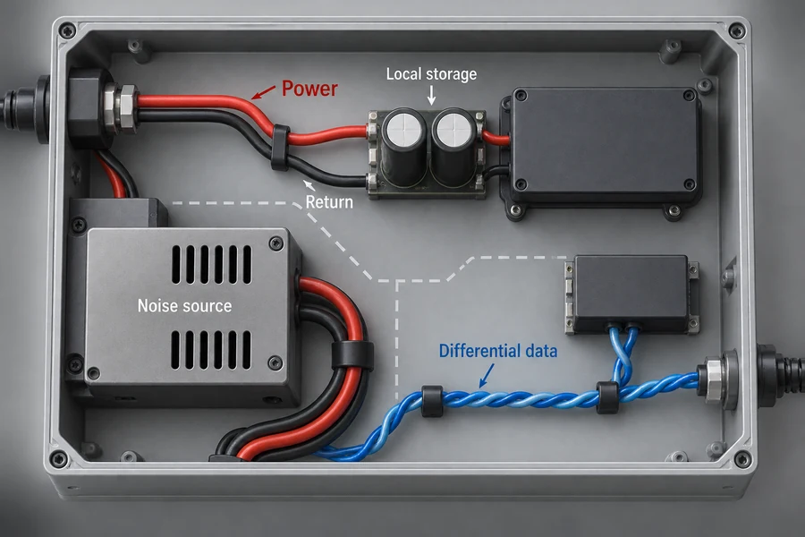
Place local energy storage and filtering from a measured impedance and transient need, not from a copied capacitor value. Keep high-current switching loops and motor or actuator wiring away from sensitive returns and communication paths. Define where chassis, power, and signal returns meet; an unlabeled ground symbol is not a grounding plan.
Gates 6–7: Define the electrical link and firmware contract
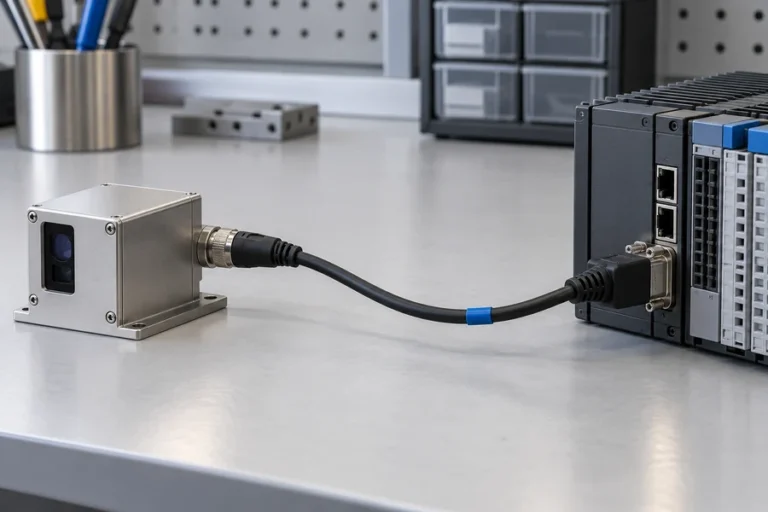
“UART,” “TTL,” or “RS-422” does not fully specify an interface. The electrical layer needs voltage levels, polarity, cable type and length, connector and pinout, shielding/return strategy, transceiver behavior, termination when required, and protection against expected transients. The data layer needs baud rate, framing, byte order, commands, checksums, response timing, diagnostics, and version rules.
Texas Instruments’ RS-422 overview shows why data rate, cable length, rise time, and termination must be considered together. A short internal logic-level link and a long differential cable solve different system problems. The practical comparison in our laser rangefinder module interface guide can help the team choose the physical layer, but the final implementation still needs cable- and host-specific verification.
Firmware must make the measurement state unambiguous. Define who owns the trigger, whether a response is synchronous or queued, when a returned distance becomes valid, how it is associated with host time or pointing state, and what happens after timeout, checksum failure, overflow, saturation, or no return. The host should never confuse “no new measurement” with a valid zero or silently reuse stale data.
Test error behavior as aggressively as the normal path. Remove or corrupt a frame, delay a response, interrupt power, request measurements faster than allowed, and restart one side of the link. Recovery rules need to be deterministic and logged. Freeze the protocol revision and compatible firmware matrix before validation evidence is collected.
Gate 8: Verify the module, integrated host, and final use separately
A passed module test does not verify the enclosure, and an enclosed bench test does not validate the final use case. Build a requirement-to-evidence matrix that identifies each requirement, responsible owner, verification method, test article, configuration, procedure, result, and approval. NASA’s systems-engineering guidance separates analysis, inspection, demonstration, and test and carries verification from lower-level items through complete system integration.
Use at least four evidence levels where the project risk warrants them:
- Module baseline: communication, basic ranging, current profile, and supplier-defined checks on a controlled bench.
- Integrated host: the final power path, cable, connector, mount, window, enclosure, firmware, and neighboring electronics.
- Environmental and interaction states: temperature, vibration or motion, contamination state, background light, target variation, and other defined host loads.
- End-to-end use: representative targets, distances, cadence, operator or control behavior, logging, faults, and recovery.
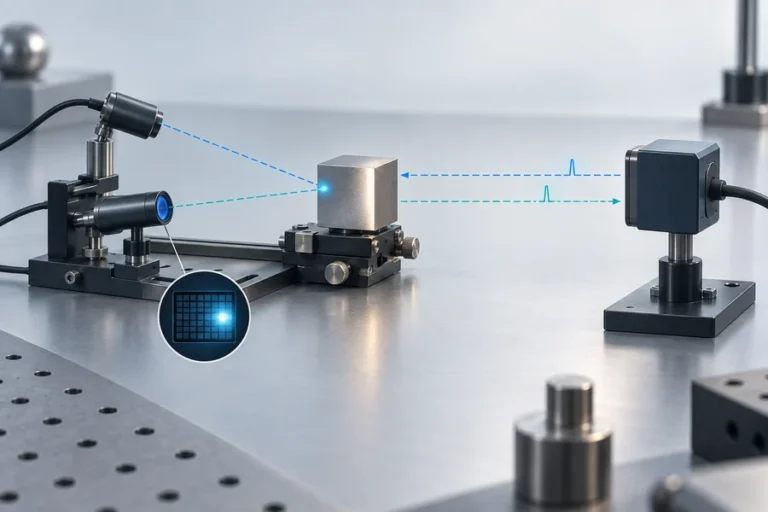
Record the reference instrument, fixture, target, distance convention, ambient state, software version, sample identity, and uncertainty where they affect the result. NIST notes that characterization and traceability depend on the operating conditions, reference standards, repeatability, and treatment of measurement uncertainty. For a practical factory-oriented sequence, use our guide to testing a laser rangefinder module before production.
Laser-safety evidence needs the same configuration discipline. IEC 60825-1 distinguishes component and finished-product responsibilities; do not convert a wavelength label or a component-level statement into a blanket claim for the integrated host. Review the applicable edition, operating modes, accessible emission, maintenance and fault states, labeling, and user information for the final product.
Gate 9: Freeze a production and service package
Production readiness means another trained team can build, test, and release the same configuration without relying on the prototype engineer’s memory. The handoff package should contain controlled mechanical drawings, optical-axis and datum definitions, window requirements, connector and pin definitions, power limits, protocol revision, compatible firmware, calibration data, assembly instructions, fixtures, acceptance criteria, and approved change rules.
Tie test records to the unit or lot and identify the configuration that produced them. Define how a reference unit or golden fixture is stored, checked, and replaced. State which tests occur at incoming inspection, after assembly, after alignment, and at end of line. Service teams also need a fault tree, permitted replacement actions, recalibration triggers, and a way to confirm the software/hardware combination in the field.
LUMEXIS supports laser rangefinder modules and related laser sources from optical and optomechanical design through electronics, firmware, weak-signal algorithms, thermal management, assembly, screening, and final test. Our Wuxi engineering and commercial office works with the 14,000-square-meter Taizhou manufacturing base, where cleanroom assembly, controlled production flow, temperature cycling, burn-in or aging screening, and final performance testing can support a configuration-controlled handoff.
Applications engineers can help with selection, integration, validation, and troubleshooting during pre-sales and after-sales stages through our engineering services. Standard products can ship within three days. Custom configurations and private-label programs follow project-specific requirements and lead times. The laser-ranging solution page shows the supported civil, industrial, and scientific context.
Frequently asked questions
When should laser rangefinder module integration start?
Start while the use case, host architecture, and enclosure are still flexible. The target model, optical clearances, mounting datum, power architecture, data link, and verification method should influence module selection. Waiting until the enclosure is nearly finished turns interface decisions into late constraints and makes failures harder to isolate.
Can the module’s maximum range become the host-system requirement?
Not without its conditions. Ask for the target size and surface, atmosphere, background, aperture, alignment, measurement mode, success rule, and operating state used for the claim. The host requirement should state representative targets and conditions, then be verified with the final optical, electrical, mechanical, and firmware configuration.
Is UART enough for an embedded laser rangefinder?
It can be enough for a short, controlled internal link, but “UART” does not define logic levels, grounding, cable behavior, framing, checksums, timing, diagnostics, or fault recovery. Longer or noisier routes may favor a differential physical layer. Choose and verify the complete link for the actual host environment.
Should boresight be checked after the system warms up?
Yes, when temperature change can shift the relationship among the module, bracket, window, chassis, and reference axis. Check the cold and stabilized states that matter to use, and record the mounting, torque, firmware, and target configuration. A short indoor alignment check may not expose a meaningful long-distance angular offset.
What should be frozen before pilot production?
Freeze the approved mechanical and optical references, window specification, power and cable design, protocol and firmware matrix, assembly sequence, alignment method, fixtures, acceptance criteria, test data format, traceability rules, and change authority. Any open item should have an owner and an explicit closure plan rather than remaining an informal assumption.
References
- NASA, 5.2 Product Integration.
- NASA, Systems Engineering Handbook appendices.
- NIST, Traceability Considerations for the Characterization and Use of Measuring Systems.
- Texas Instruments, AN-1031 TIA/EIA-422-B Overview.
- Analog Devices, Line and Load Transient Testing for Power Supplies.
- IEC, IEC 60825-1: Safety of laser products—equipment classification and requirements.
Planning an OEM design review? Send our applications engineers the target and range envelope, wavelength, window, mechanical envelope, available power, interface, operating environment, measurement cadence, expected volume, and current project stage. We can recommend a standard module, confirm availability, or scope a custom configuration and validation plan.