










If you are asking what is laser ranging, the short answer is that it is an optical distance measurement whose trustworthy result depends on more than a distance reading. A usable result depends on how the target returns light, how the receiver rejects unwanted signals, and whether the timing or phase measurement remains stable in the installed environment.
For OEM teams, that distinction matters early. The right ranging method is not chosen from a headline range alone; it is chosen from the target, working distance, update rate, mechanical envelope, interface, and validation method.
Laser ranging is a non-contact way to measure distance by sending controlled laser light toward a target, detecting returned light, and converting either its round-trip travel time or its modulation phase into distance. The two common approaches are direct time-of-flight and phase-shift measurement. Both require a system that can separate a useful return from optical, electronic, and environmental uncertainty.
What Is Laser Ranging and What Does It Measure?
Laser ranging measures the line-of-sight distance between an instrument reference point and a target surface or reflector. In the simplest pulsed case, the system measures a round-trip delay and calculates distance as:
distance = (speed of light × round-trip time) / 2
The division by two matters because the measured light travels to the target and back. The equation is straightforward; the engineering challenge is determining a trustworthy delay when the return can be weak, spread across a target, mixed with ambient light, or shifted by the system’s own signal path.
NASA’s description of satellite laser ranging is a useful high-precision example: short pulses are sent to retroreflector-equipped targets and the round-trip time is measured directly. An OEM module operates at a different scale and under different constraints, but the measurement logic is the same: define the reference, detect a return, and account for the conditions that affect it.
The two main laser ranging principles
### Direct time-of-flight ranging
Direct time-of-flight, often shortened to dToF, sends a short optical pulse and timestamps the returned signal. It is a natural fit when a system needs discrete distance updates, when targets may be farther away, or when the design can support the required timing and detection chain.
The timing path includes more than a laser pulse and a detector. Transmit drive behavior, optical path delay, detector response, amplifier bandwidth, thresholding, and firmware all contribute to what the system reports. A reliable design establishes how these contributions are calibrated and how the measurement behaves across the intended temperature, target, and ambient-light conditions.
Direct time-of-flight is not automatically a guarantee of long usable range. Target reflectivity, target size, beam divergence, receiver aperture, filtering, detector sensitivity, and signal processing all influence the returned signal. A distance claim without its target and test conditions is incomplete.
### Phase-shift ranging
Phase-shift ranging uses intensity-modulated light instead of an isolated short pulse. The system compares the phase of the transmitted modulation with the phase of the received modulation; the phase difference corresponds to travel distance.
This approach can be effective for moderate working distances and high-resolution measurement, but it has a design constraint: one modulation frequency repeats in phase. A system therefore needs an ambiguity strategy, such as using multiple frequencies or another method that matches the intended range. The phase measurement also needs stable electronics and a signal-processing approach that remains robust when return conditions change.
For a broader comparison of timing approaches, see our guide to time-of-flight distance measurement. The practical decision is not which method is universally better; it is which method produces a defensible result for the target and integration constraints.
Why target conditions change the answer
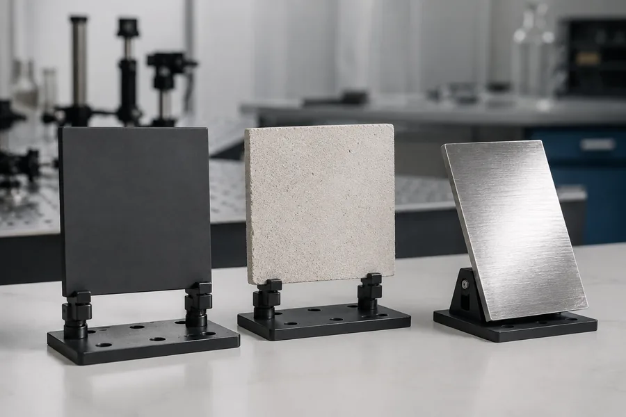
Laser ranging is an optical measurement, so the target is part of the measurement system. A rough light-colored surface, a dark coated surface, and an angled metallic surface can return light very differently. The surrounding geometry can matter as well: a small foreground feature, an edge, a window, or a nearby reflective structure may create returns the system must identify or reject.
Beam divergence adds another layer. As working distance increases, the illuminated spot can grow. If the spot extends beyond the intended object, the return can include background information. That is why a useful validation plan specifies target material, target angle, target size, background, and ambient-light condition rather than relying on a single convenient reference panel.
The same discipline applies to wavelength and receiver choices. A wavelength decision affects source and detector options, optical components, and safety design; it should not be treated as a standalone range guarantee. Our article on laser rangefinder maximum range explains how the target, optics, atmosphere, and detection path work together.
From a principle to an OEM integration requirement
Before selecting a laser rangefinder module, translate the application into conditions a supplier can evaluate. Start with the distance interval and update rate, then define the target and its movement, the acceptable error behavior, the mounting datum, power budget, host interface, enclosure window, and operating environment.
This turns a generic distance request into an engineering brief. It also makes sample evaluation more useful: the team can confirm whether the sample configuration, firmware, target conditions, and acceptance method match the intended host system.
LUMEXIS designs and manufactures laser sources and modules for measurement, sensing, industrial, and scientific systems. Our engineering and commercial team in Wuxi works with a Taizhou manufacturing base that covers 14,000 square meters, supporting optical, electronics, firmware, thermal-management, and test-method work in one engineering flow. For an OEM program, we can help turn system constraints into a module-selection and validation plan, including standard configurations and suitable custom or private-label requirements.
A practical validation sequence
Use a staged approach rather than treating a first reading as final proof.
- Define the application reference: where does the measurement begin, and which target surface defines the required distance?
- Create a target set that represents expected material, angle, size, and background conditions.
- Record the sample configuration, firmware revision, interface settings, power condition, and test method before comparing results.
- Check repeatability and failure behavior across the relevant operating conditions, not only the best-case target.
- Review mounting, window, cable routing, host timing, and data handling before the design is released.
This sequence is useful whether the application is a fixed industrial sensor, a railway or infrastructure inspection instrument, a scientific measurement setup, or a mobile civil sensing system. The difference is the conditions you must control and document.
FAQ
### Is laser ranging the same as LiDAR?
Laser ranging measures distance along one measurement path. LiDAR systems use laser-ranging measurements, often with scanning and position information, to build spatial data. A single-point module may be part of a larger LiDAR or sensing system, but the system-level output depends on optics, scanning, software, and calibration beyond the range measurement itself.
### How accurate is laser ranging?
Accuracy depends on the measurement method, timing or phase processing, target, optics, calibration, temperature, and test conditions. Evaluate accuracy against a stated configuration and method. A value quoted without the target, distance, environment, and acceptance definition does not show how the installed system will behave.
### Can a laser rangefinder measure dark or angled targets?
It may, but the return signal can be weaker or directed away from the receiver. The right question is whether the module and optical design have been validated with the target material, angle, distance, and background that the application actually uses. Include those conditions in the sample test plan.
### Why does a laser rangefinder need signal processing?
The received optical signal can be weak and may include ambient light, optical reflections, detector noise, and returns from nearby objects. Signal processing helps the system identify a valid return and report distance consistently. The required approach depends on the ranging method and application conditions.
### What should an OEM share when requesting a laser-ranging recommendation?
Share the distance interval, target material and size, target angle or movement, update rate, mechanical envelope, power and interface constraints, operating environment, and how the host will use the result. Those inputs allow an applications engineer to propose a testable configuration rather than a generic module recommendation.
Choose the method around the measurement, not the headline
Laser ranging works when optics, detection, processing, and validation are designed around a defined measurement condition. If you are integrating a laser rangefinder into a civil, industrial, or scientific system, send our team the target, distance interval, size constraint, interface, and operating environment. We can recommend a standard option where it fits, confirm availability for standard products, or review a custom requirement with an applications engineer through our contact page.