







A maximum-range figure looks precise, but it can hide the conditions that made the measurement possible. Change the target surface, beam interception, visibility, ambient light, update rate, or receiver threshold, and the same hardware may stop producing dependable returns well before the quoted distance.
Laser rangefinder maximum range is the farthest distance at which the complete system can detect a returned pulse above its decision threshold with the required reliability. It depends on transmitter energy and divergence, two-way atmospheric transmission, target reflectance and size, receiver sensitivity and aperture, background noise, and signal processing—not on one module parameter alone.
That definition matters when you are comparing modules for inspection, surveying, research instruments, or commercial UAV altimetry. A fair comparison starts with common conditions and ends with a measurable success criterion.
Laser rangefinder maximum range is a signal-budget limit
In a pulsed time-of-flight rangefinder, the source emits a short optical pulse. A small fraction reaches the target, an even smaller fraction returns toward the receiver, and the detector converts that echo into an electrical signal. The measurement becomes unavailable when the system can no longer distinguish a valid echo from background light, detector noise, electrical noise, and unwanted reflections.
This is why maximum range is not the same as accuracy. Accuracy describes how close a valid measurement is to the true distance. Maximum range describes whether a valid measurement can be obtained at all. A system can be accurate at 500 m and still fail to detect a low-return target at 700 m.
It also helps to separate three versions of “range”:
- Calculated range comes from a model and its assumptions.
- Specified range comes from a stated test target and environment.
- Usable range is what the installed system achieves across the targets, conditions, and success rate that matter to the application.
For the underlying timing principle, see our explanation of how a laser rangefinder works.
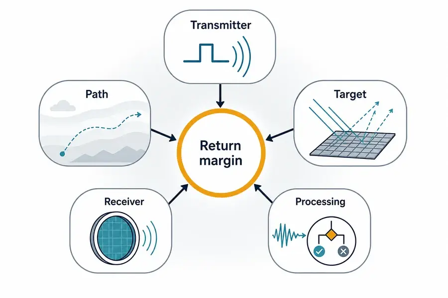
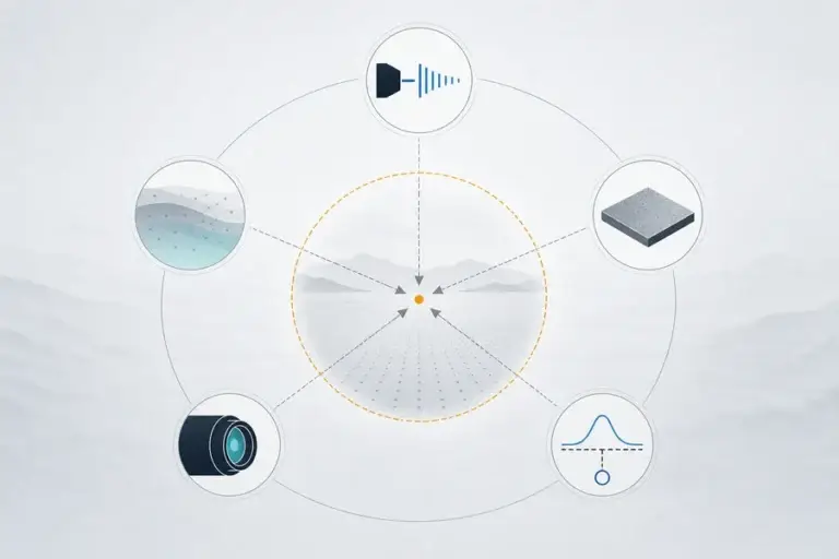
Five groups of variables determine the return
A range equation can look intimidating, but its engineering logic is straightforward. The returned optical power increases with useful transmitted energy, receiver collection area, target return, and optical efficiency. It falls as distance, divergence, losses, and attenuation increase. Detection then depends on whether that return clears the receiver’s noise-dependent threshold.
1. Transmitter and beam
Pulse energy matters because it sets the optical energy available for the round trip. Yet energy at the source is not energy on target. Transmit-optics efficiency, beam clipping, window loss, alignment, and beam divergence all change the delivered footprint.
A narrower beam concentrates more energy within a smaller area, which can help when pointing is controlled and the target intercepts the beam. It can hurt robustness when platform motion, boresight error, vibration, or target uncertainty causes the spot to miss. The best divergence is therefore an integration decision, not a universal minimum.
2. Propagation path
The pulse crosses the atmosphere twice. Aerosols, haze, fog, rain, dust, and absorption reduce the outbound energy and then reduce the return again. Meteorological visibility is often used as a practical condition for range specifications, but it should be stated rather than assumed.
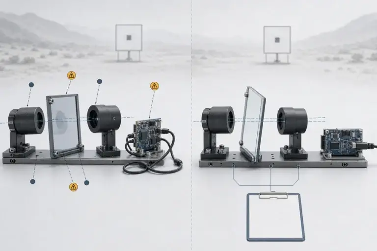
The optical window in the installed system belongs in this path too. Contamination, coating mismatch, angle, internal reflection, and temperature-dependent alignment can consume margin that was available during an open-bench test.
3. Target return
Reflectance must be considered at the laser wavelength. A surface that looks bright to the eye does not necessarily provide the same return in the near-infrared or short-wave infrared. Surface roughness and angle also determine where the reflected energy goes.
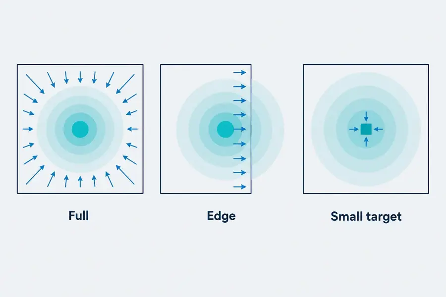
Target size matters relative to beam footprint. If the illuminated object is larger than the spot, it can intercept most of the outgoing beam. If the target is smaller, near an edge, or partly occluded, much of the energy misses it or illuminates background objects. This is one reason “building range,” “small-object range,” and “reflective-target range” are not interchangeable specifications.
4. Receiver and noise
The receiver aperture controls how much returning light can be collected. Optical throughput, spectral filtering, detector responsivity, detector gain, bandwidth, field of view, and front-end electronics determine how much of that optical signal becomes a usable electrical pulse.
Receiver design also controls background. A wider field of view may tolerate alignment error, but it can admit more ambient light. A narrow optical filter can reduce unwanted light, but its wavelength and angle behavior must suit the source and operating temperature. Bright sunlight can therefore shorten operational range even when target and atmosphere are unchanged.
5. Detection and processing
The last limit is not merely hardware. Thresholding, pulse-shape checks, time gating, background estimation, multiple-return handling, and averaging all influence whether a weak echo is accepted. The acceptance rule must reject noise without discarding too many real returns.
Combining multiple shots can improve weak-signal detection, but it trades measurement rate for sensitivity. It may also require the target and platform to remain sufficiently stable during the integration period. A high quoted range achieved with extensive averaging is not equivalent to the same range at a fast update rate.
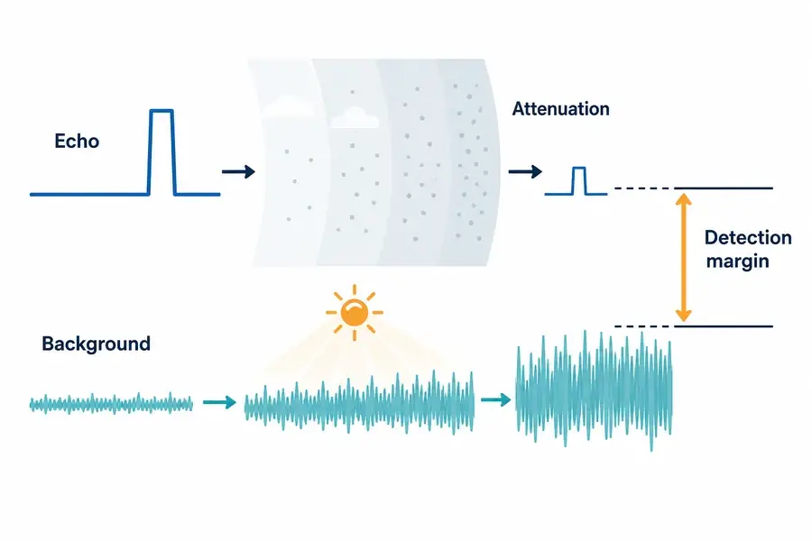
Atmosphere and ambient light reduce detection margin differently
Atmospheric attenuation weakens the desired signal during both legs of the path. Ambient light raises the receiver’s noise floor. Both reduce the margin between a real echo and the decision threshold, but they call for different responses.
If poor visibility is the dominant problem, more transmitted energy cannot automatically recover the loss within the system’s power, thermal, and safety constraints. If background light is dominant, spectral filtering, field-of-view control, detector choice, and time gating may matter more. The correct diagnosis depends on measured return and noise behavior, not just failed readings.
For application-level constraints, our laser-ranging solution overview connects source, receiver, optics, and integration decisions.
Compare range specifications under the same conditions
A useful datasheet should let you reconstruct the test. Before comparing two modules, normalize the conditions below.
| Condition | What to request | Why it changes the result |
|---|---|---|
| Target | Reflectance at wavelength, dimensions, surface type | Sets returned energy and beam interception |
| Geometry | Incidence angle, target position, pointing tolerance | Changes where the reflected energy travels |
| Atmosphere | Visibility and weather condition | Sets two-way path attenuation |
| Ambient light | Daylight or irradiance condition | Changes receiver background noise |
| Optical path | Window, coatings, cleanliness, alignment | Adds losses and possible stray returns |
| Operating mode | Pulse rate, averaging, update rate | Trades speed, energy, and detection sensitivity |
| Receiver criterion | Required valid-return rate and false-return limit | Defines what “detectable” means |
| Environment | Temperature, supply voltage, motion | Can shift source, detector, optics, and processing behavior |
Do not accept “high-reflectivity target” as a complete condition. Ask for the reflectance value, wavelength, target size, angle, and whether the target fills the beam footprint. Our laser rangefinder module datasheet guide provides a broader checklist for reading module specifications.
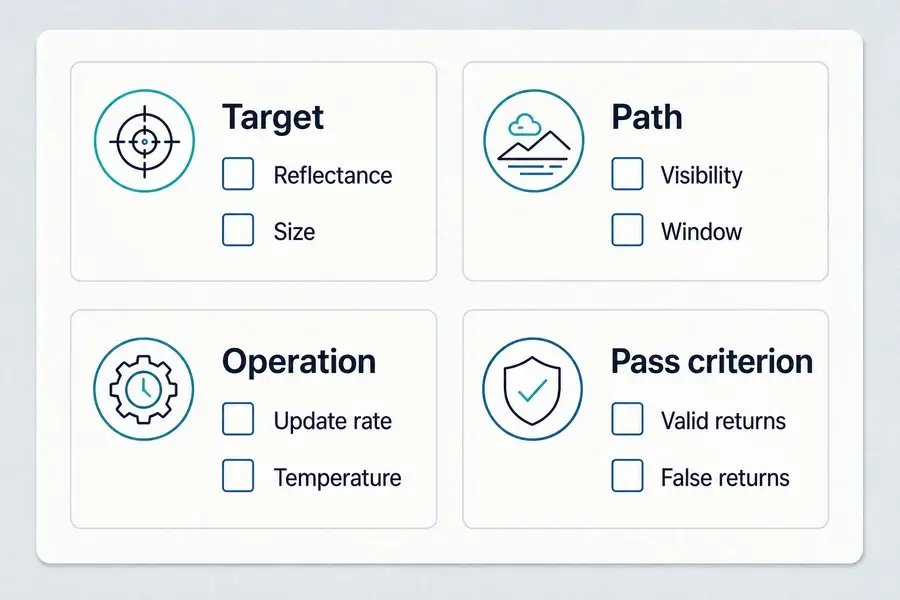
Verify usable range in the actual integration
Start with controlled targets at known distances, then add real integration variables one at a time. Use representative low-, medium-, and high-return surfaces at the wavelength of interest. Record target size and angle, window state, visibility, ambient condition, temperature, supply, update rate, and software configuration.
A single successful reading is weak evidence. Run repeated trials and report the valid-return percentage, spread of valid measurements, false returns, and failure modes. Then test across the operating envelope that matters to your platform. This approach reveals whether the limit comes from energy, pointing, target interception, path attenuation, background light, receiver noise, or the acceptance logic.
Lumexis develops laser rangefinder modules with in-house optical, electronic, firmware, weak-signal algorithm, and thermal-management capabilities. Our applications engineers can support selection, integration, validation, and troubleshooting. For suitable OEM projects, engineering and customization support can address envelope, interface, optical window, operating mode, and qualification requirements without treating a catalog range as the whole design.
Frequently asked questions
Is maximum range the same as accuracy?
No. Maximum range is a detection limit under stated conditions. Accuracy is the difference between a valid measurement and the true distance. A system may maintain good accuracy for detected returns while its valid-return rate falls as distance, target return, or visibility worsens.
Does a narrower beam always increase maximum range?
No. A narrower beam increases irradiance on a well-pointed target, but it also reduces pointing tolerance. Platform motion, boresight error, vibration, and small targets can make a narrow beam miss more often. Divergence must be chosen with target size and pointing performance.
Why can a rangefinder work farther at night?
Lower ambient light can reduce the optical background reaching the detector, increasing the margin between a weak return and the noise-dependent threshold. The improvement depends on receiver field of view, spectral filtering, detector behavior, and processing; it is not a fixed multiplier.
Can averaging always extend range?
Averaging or integrating multiple returns can improve sensitivity when the signal is repeatable, but it reduces update rate and may fail when the platform or target moves too much during the integration period. Compare range and rate together.
What target reflectivity should a range specification use?
There is no single value that represents every application. Define reflectance at the operating wavelength and choose targets that bracket the expected field surfaces. The specification should also state target size, angle, beam interception, atmosphere, ambient light, and the required valid-return rate.
If you are defining a new system, send us the target type and size, required range and update rate, wavelength preference, optical window, mechanical envelope, interface, temperature range, and platform motion. Our team can review the signal-budget assumptions, recommend a standard module where it fits, or scope a custom or private-label configuration. Standard products can ship within three days; custom lead time is confirmed against the project.
References
- RIEGL, Operation of a Pulsed Laser Distance Meter.
- Ma et al., The Short-Range, High-Accuracy Compact Pulsed Laser Ranging System, Sensors 22, 2146 (2022).
- RIEGL, LD05-A10GF Technical Data.
- NIST, Ranging Tests for Laser Scanners.