








A laser rangefinder module may appear suitable when its datasheet shows the required distance and accuracy. Problems often begin after the sample is installed. A dark target produces fewer valid readings. The host window creates internal reflections. The communication link becomes unstable. The module reaches its stated range only under conditions that do not match the actual application.
To choose a laser rangefinder module, first define the target, minimum and maximum distance, required accuracy, measurement rate, environment, size, power budget and host interface. Then compare wavelength, beam divergence, receiver aperture, minimum range, multi-target behavior and qualification evidence under the same test conditions. Do not select a module from maximum range alone.
This guide explains how to turn an application requirement into a practical module-selection and validation plan.
Table of Contents
Quick Laser Rangefinder Module Selection Table
| Application | Main selection priorities | Common mistake |
|---|---|---|
| Civil UAV altimetry | Low weight, power, update rate, slant range, target footprint and vibration | Selecting by vertical altitude without calculating maximum slant range |
| UAV mapping or inspection | Timing consistency, interface, boresight, range gate and target response | Ignoring synchronization with the camera, GNSS or flight controller |
| Surveying equipment | Minimum range, accuracy, target variation and repeatability | Treating resolution as guaranteed measurement accuracy |
| Railway or infrastructure inspection | Surface angle, vibration, temperature, window design and retained alignment | Testing only on a flat white target |
| Fixed remote sensing | Long-range margin, aperture, atmosphere, multi-return output and thermal stability | Using a large-building range claim for smaller field targets |
| Scientific instruments | Protocol access, controlled timing, repeatability and configuration control | Buying a module without documented commands or revision control |
1. Start With the Measurement Problem
Before comparing products, describe the measurement task without referring to a specific module.
A useful requirement should answer these questions:
| Requirement | What to define |
| Target | Material, color, size, reflectivity, angle and expected motion |
| Distance | Minimum working distance, normal distance and maximum required distance |
| Accuracy | Maximum allowed error under defined conditions |
| Measurement rate | Required valid results per second |
| Environment | Sunlight, temperature, humidity, dust, rain, haze and vibration |
| Optical path | Bare module or operation behind a protective window |
| Mechanical limits | Maximum dimensions, weight, mounting method and optical-axis location |
| Electrical limits | Input voltage, peak current, average power and startup behavior |
| Data interface | TTL, UART, RS422, RS232 or another supported interface |
| Output behavior | Single measurement, continuous output, multi-target reporting or range gating |
| Qualification | Sample test, environmental test and production acceptance method |
Avoid requirements such as:
Need a small 5 km rangefinder with good accuracy.
Replace them with a testable statement:
The installed module must measure a 2 m × 2 m painted structure at 5 km with at least a 95% valid-reading rate, within ±1 m, in daylight and within the defined temperature range. Results must be transmitted over a 1.5 m cable to the host controller at 5 Hz.
The second version gives the supplier and the system engineer a common acceptance condition.
2. Choose the Correct Measurement Principle
Not every laser distance module uses the same measurement method.
Pulsed time of flight
A pulsed time-of-flight module emits a short optical pulse and measures how long the reflected signal takes to return.
The basic equation is:
Distance = speed of light × round-trip time ÷ 2
Pulsed time of flight is commonly used for kilometer-class ranging because the transmitter, receiver and timing system can be designed around weak returns from distant targets.
It is usually the first architecture to evaluate for:
- Long-range outdoor measurement
- UAV and airborne ranging
- Remote infrastructure inspection
- Fixed observation instruments
- Long-distance surveying
- EO/IR and pointing systems
The final result still depends on pulse energy, divergence, receiver sensitivity, aperture, atmospheric loss and signal processing. The equation alone does not guarantee accuracy or maximum range.
Phase-shift measurement
A phase-shift module transmits modulated light and measures the phase difference between the transmitted and returned signals.
It can provide fine measurement resolution over a controlled distance interval. However, the system must manage phase ambiguity, surface response, calibration and ambient-light interference.
This method may be suitable when fine repeatability is more important than a broad kilometer-scale measurement window.
Triangulation
A triangulation sensor projects a spot and observes its position from a separate optical angle. The detected spot position changes with distance.
Triangulation is mainly suitable for short-range displacement, positioning and profile measurement. Its performance depends heavily on the optical baseline, target angle, surface texture and mechanical stability.
It should not be treated as a direct replacement for a long-range pulsed module.
3. Interpret Maximum Range Correctly
The largest number on a datasheet is not a universal working distance.
Maximum range is normally measured using a defined target, atmosphere, visibility, alignment and detection rule. A result measured against a large, bright structure cannot be transferred directly to a small, dark or angled target.
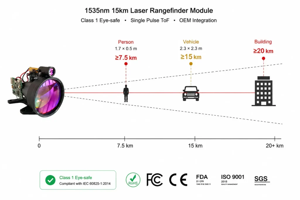
Lumexis, for example, states separate ranges for a 2.3 m × 2.3 m target and a large target. Its current 1535 nm series spans at least 3.2 km to 15 km on the defined 2.3 m × 2.3 m target and up to at least 20 km on a large target, depending on the model.
When reviewing a range specification, request the following information:
- Target dimensions
- Target material and reflectivity
- Target angle
- Visibility or atmospheric condition
- Background-light condition
- Required valid-reading probability
- Measurement mode and repetition rate
- Operating temperature
- Whether the result is from the bare module or installed system
Build in range margin
A system that must operate at 5 km should not automatically use a module that barely reaches 5 km under ideal conditions.
Additional margin may be needed for:
- Dark surfaces
- Small targets
- Oblique target angles
- Haze or airborne particles
- Host-window losses
- Pointing error
- Boresight drift
- Temperature variation
- Production variation
The correct margin depends on the application. It should be based on representative testing, not a fixed percentage applied to every system.
4. Compare 905 nm and 1535 nm at System Level
Wavelength affects the transmitter, detector, optics, safety analysis, cost and available range margin.
It does not determine the complete result by itself.
When 905 nm may be appropriate
A 905 nm architecture may be suitable when the project prioritizes:
- A compact semiconductor-source design
- A mature silicon-detector supply chain
- Short- to medium-range measurement
- Lower component cost
- High-volume commercial integration
- A range requirement that can be achieved within the final product’s safety limits
When 1535 nm may be appropriate
A 1535 nm architecture may be suitable when the project needs:
- Kilometer-class measurement
- Higher transmitted-energy options within a defined eye-safety design
- An erbium-glass pulsed source
- Reduced sensitivity of common silicon image sensors to the transmitted wavelength
- Compact long-range OEM modules
- Operation in civil UAV, surveying, inspection or scientific equipment
The 1.5 µm receiver path commonly uses an InGaAs-class detector rather than a silicon detector. This can change receiver cost, biasing, noise control and supply-chain planning. Lumexis therefore recommends comparing the complete transmitter, receiver and optical chain rather than comparing wavelength labels alone.
Practical selection rule
Compare 905 nm and 1535 nm candidates using:
- The same target
- The same required distance
- The same ambient-light condition
- The same valid-reading requirement
- The same package limits
- The same safety boundary
- The same production quantity
A wavelength should be selected because the complete architecture fits the requirement, not because one wavelength is described as universally superior.
5. Verify Eye Safety for the Final Configuration
“Eye-safe wavelength” and “Class 1 product” are not interchangeable statements.
IEC 60825-1 defines the classification and safety requirements for laser products. The accessible emission, wavelength, pulse conditions, apertures, optics and operating modes all affect the final classification. A module that is supplied to an OEM also does not remove the need to assess the completed host product.
Ask the supplier:
- Which exact module configuration was classified?
- Which operating modes were included?
- Which aperture and optics were present?
- Does the classification cover continuous ranging?
- Are any service or fault conditions relevant?
- What safety documentation applies to the supplied configuration?
Lumexis identifies its current 1535 nm rangefinder modules as Class 1 for their defined module configurations. It also states that the completed host product requires assessment in its final optical and operating configuration.
Do not assume that adding a window, lens, telescope or other optical component leaves the accessible emission unchanged.
6. Separate Accuracy, Resolution and Repeatability
These terms describe different performance characteristics.
Accuracy
Accuracy describes how close the reported distance is to the accepted reference distance.
A module specified at ±1 m may report any value within that stated error band under the specified conditions.
Resolution
Resolution is the smallest output increment or displayed change.
A module may output values in 0.1 m steps while having an absolute accuracy of ±1 m. The smaller number does not replace the accuracy specification.
Repeatability
Repeatability describes how closely repeated measurements agree under the same conditions.
A module can provide tightly grouped results that still contain a systematic offset. It can also have acceptable average accuracy but inconsistent individual readings.
Recommended acceptance method
For each representative target and distance:
- Collect a defined number of measurements.
- Record the percentage of valid results.
- Calculate the average error.
- Record the maximum absolute error.
- Calculate measurement spread or standard deviation.
- Repeat at relevant temperatures and light levels.
- Repeat after installation in the final enclosure.
Do not accept a sample based on three successful readings from one bright indoor target.
7. Calculate Beam Footprint From Divergence
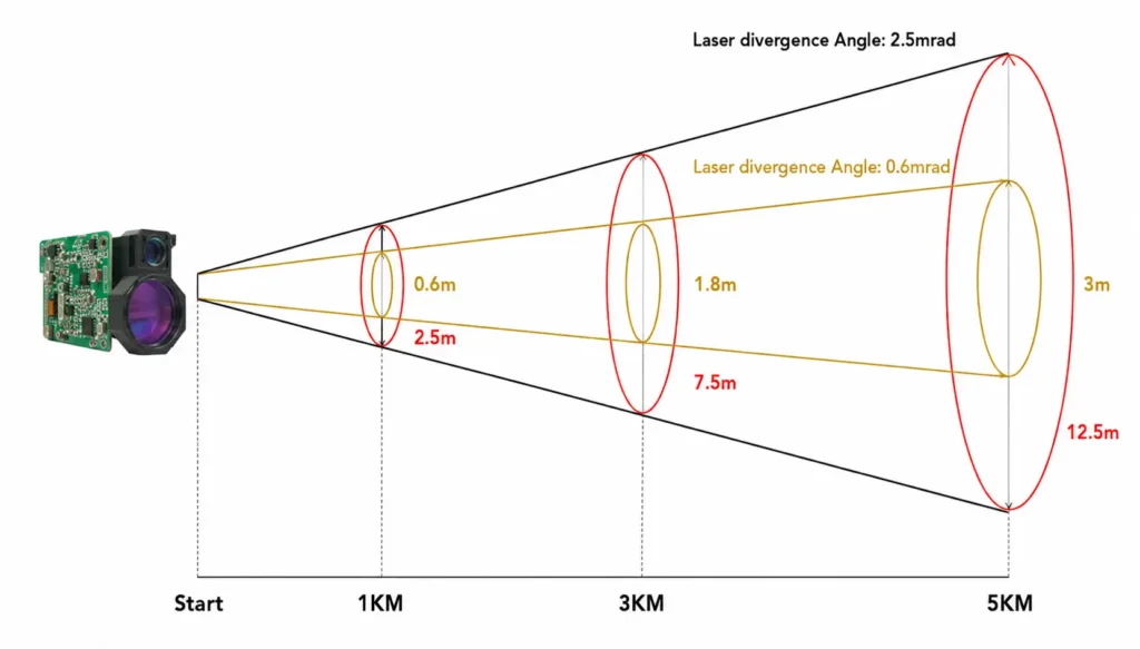
Beam divergence determines how quickly the laser footprint expands with distance.
A useful first approximation is:
Additional beam diameter ≈ divergence in radians × distance
For a module with 0.3 mrad divergence:
| Distance | Approximate added footprint |
| 1 km | 0.3 m |
| 3 km | 0.9 m |
| 5 km | 1.5 m |
| 10 km | 3.0 m |
This calculation does not include the initial beam diameter or every beam-shape detail, but it is useful during early target analysis.
Safran Vectronix gives a similar practical explanation: a 0.5 mrad beam has a diameter contribution of approximately 0.5 m at 1,000 m. It also notes that narrow divergence helps place more energy on the selected target.
Narrower is not always easier
A narrower beam can improve target fill on a compact distant target. It also increases sensitivity to:
- Pointing error
- Platform vibration
- Transmit-axis alignment
- Receive-axis alignment
- Boresight drift
- Mounting distortion
- Temperature-related movement
A 0.3 mrad beam may look preferable to a 0.6 mrad beam, but only when the host platform can keep the beam on the target.
Evaluate divergence together with pointing stability and receiver field of view.
8. Match Measurement Rate to Target Motion
Measurement rate is normally expressed in hertz.
A 10 Hz module can produce up to ten measurement cycles per second under its defined operating mode. This does not automatically mean the host receives a fully processed, timestamped and usable result every 100 milliseconds under all conditions.
Separate these timing terms:
- Power-up time
- Command acceptance time
- Laser preparation time
- Measurement time
- Echo-processing time
- Serial-transmission time
- Host parsing time
- Application response time
For a moving UAV or inspection platform, calculate how far the platform or target travels between measurements.
At 20 m/s:
- 1 Hz represents approximately 20 m of travel between measurements.
- 5 Hz represents approximately 4 m.
- 10 Hz represents approximately 2 m.
The correct rate therefore depends on platform speed, control-loop needs, pointing behavior and the acceptable spatial distance between samples.
Also verify whether the module supports:
- Host-triggered single measurements
- Continuous ranging
- Configurable frequency
- Hardware triggering
- Measurement timestamps
- Status output for invalid or missing returns
9. Check Minimum Range, Multi-Target Output and Gating
Maximum distance attracts attention, but minimum range can determine whether a module works in the real system.
A pulsed rangefinder may need time to recover from the transmitted pulse, optical cross-talk or a strong nearby reflection. This creates a minimum measurable distance.
The Lumexis module family, for example, lists model-dependent minimum ranges from 15 m to 70 m. Longer-range configurations do not necessarily retain the minimum range of smaller models.
Multi-target reporting
A laser pulse may encounter:
- Vegetation before a building
- A fence before the ground
- Cables before a structure
- Several vehicles along the beam path
- Dust, rain or other scattering objects
Multi-target output allows the module to report more than one valid return when the returns can be separated.
Safran Vectronix explains that its modules can identify separate targets when sufficient distance separation exists, with results ordered according to the module’s signal-processing logic.
Do not assume that “first target,” “last target” and “strongest target” mean the same thing.
Range gating
Range gating limits accepted returns to a defined distance interval.
For example, an inspection system looking at a structure between 2.0 and 2.5 km may reject signals outside that window. This can reduce unwanted foreground or background returns.
Ask the supplier:
- How is the gate configured?
- Is it stored after power cycling?
- What happens when no return falls inside the gate?
- How are multiple returns ordered?
- What minimum separation is needed?
- How are invalid and saturated returns reported?
10. Evaluate Size, Weight, Power and Receiver Aperture Together
Size, weight and power are often grouped as SWaP. These values should not be evaluated independently.
A larger receiver aperture can collect more returned optical energy. However, it also increases:
- Module dimensions
- Weight
- Host-window size
- Enclosure volume
- Alignment sensitivity
- Cost
Lumexis currently lists 1535 nm models starting at approximately 48 × 21 × 31 mm and 33 g. Longer-range models use larger receive apertures and packages, reaching a 52 mm aperture and approximately 191 g in the 15 km model class.
Review both average and transient power
Request:
- Input-voltage range
- Standby consumption
- Average consumption at the specified rate
- Peak current during pulse preparation
- Startup current
- Continuous-mode power
- Behavior during undervoltage
- Required supply filtering
A module with low average power can still create a short current transient that disturbs the host processor or other sensors.
Test the sample with the intended power supply and cable, not only with a laboratory supply next to the module.
11. Select the Interface for the Installed System
An interface label does not define the complete electrical and communication behavior.
TTL or UART
A local UART-style interface may be suitable when:
- The host controller is close to the module.
- Cable length is short.
- The electrical environment is controlled.
- Both devices use compatible logic levels.
- The host can implement the documented protocol and recovery behavior.
UART does not define the connector, pinout, voltage level, baud rate, checksum or command format. Those details must come from the exact module protocol.
RS422
RS422 may be more appropriate when:
- The cable is longer.
- The environment contains electrical noise.
- Differential signaling is preferred.
- The module is separated from the main controller.
- The system needs better signal integrity than a local single-ended link can provide.
Do not choose an interface by name alone. Review:
- Signal levels
- Cable length
- Cable impedance
- Grounding
- Shielding
- Connector retention
- ESD protection
- Message framing
- Timeout behavior
- Restart and recovery behavior
Lumexis supplies model-dependent TTL and RS422 options across its current rangefinder family. Its integration guidance also recommends treating the released protocol and electrical documentation as the interface contract.
12. Treat the Host Window and Mount as Optical Components
A protective window becomes part of the rangefinder.
Its material, coating, thickness, angle and spacing can affect:
- Transmission at the laser wavelength
- Internal reflections
- Transmit-to-receive cross-talk
- Beam direction
- Receiver field of view
- Condensation behavior
- Mechanical alignment
A window that appears clear to the human eye may not have suitable transmission or antireflection performance at 1535 nm.
Window review checklist
Confirm:
- Transmission across the module wavelength range
- Antireflection coating performance
- Clear aperture around transmit and receive optics
- Window thickness and flatness
- Window angle or parallelism requirement
- Distance between the window and module
- Internal reflection paths
- Sealing and condensation control
- Mounting tolerance
- Performance after final assembly
Lumexis recommends validating the complete installed optical stack rather than assuming a bare-module result will transfer unchanged. Its current integration guidance also provides model-specific starting points for clear aperture, window spacing and transmission.
Mechanical mounting
Use the defined mounting surfaces.
Avoid:
- Applying mechanical load through optical assemblies
- Distorting the module housing
- Blocking apertures
- Forcing cable bends near the connector
- Using an undefined housing surface as the optical datum
After installation, verify the relationship between the laser axis, receiver field and any camera or pointing sensor.
How to Evaluate a Sample Before Design Release
A proper sample test should reproduce the intended system as closely as practical.
Recommended test matrix
| Test category | Minimum evaluation |
| Target variation | Bright, dark, rough, smooth and angled representative targets |
| Distance | Minimum, normal and maximum operating distances |
| Ambient light | Indoor, daylight and bright-background conditions where relevant |
| Temperature | Relevant low, room and high operating points |
| Measurement rate | Single mode and required continuous rate |
| Valid-reading rate | Percentage of valid measurements for each condition |
| Accuracy | Average and maximum error against a traceable reference |
| Repeatability | Measurement spread over repeated samples |
| Power | Startup, standby, single-shot and continuous operation |
| Interface | Normal frames, partial frames, timeout, restart and disconnected cable |
| Host window | Bare module compared with final window and enclosure |
| Mechanical | Final mount, cable routing, vibration and retained boresight |
| Multi-target | Representative foreground and background objects |
| Range gate | Acceptance and rejection inside and outside the selected window |
Record the following identifiers with every result:
- Module model
- Module serial number
- Hardware revision
- Firmware revision
- Protocol revision
- Host hardware
- Host firmware
- Cable assembly
- Power-supply configuration
- Window configuration
- Target description
- Test date and environment
Without this record, it is difficult to determine whether a later performance change came from the module, host, firmware, test setup or production revision.
What Evidence Should a Supplier Provide?
A professional evaluation should include more than a specification sheet.
Request the documents relevant to the quoted configuration:
| Document or evidence | Why it matters |
| Technical datasheet | Defines optical, electrical, mechanical and environmental limits |
| 2D drawing | Defines dimensions, mounting features and optical-axis position |
| 3D model | Supports enclosure and interference review |
| Communication protocol | Defines commands, output frames, status and errors |
| Test conditions | Explains the target and environment behind range claims |
| Laser-safety documentation | Identifies the configuration and assessment boundary |
| Sample inspection record | Connects the delivered unit to measured results |
| Environmental test information | Supports temperature, vibration and shock requirements |
| Change-control process | Reduces uncontrolled differences after design-in |
| Production traceability | Connects serial numbers, revisions and outgoing inspection |
Also ask what the supplier tests during production.
Relevant controls may include:
- Incoming component inspection
- Laser-output verification
- Optical-axis alignment
- Receiver and electronics testing
- Range calibration
- Aging or burn-in
- Temperature screening
- Communication testing
- Final functional inspection
- Visual and packing inspection
A high-performing engineering sample is not enough when the production process cannot reproduce it.
Practical Module Selection Examples
Example 1: Civil UAV altitude measurement
Assume the UAV operates up to 1,000 m above the ground but can bank during flight.
Do not select a 1 km module without calculating slant range. At an angle, the line-of-sight distance is longer than the vertical altitude.
Priorities include:
- Maximum slant range
- Ground and vegetation response
- Weight
- Average and peak power
- Measurement rate
- Vibration
- Interface latency
- Timestamping
- Boresight
- Host-window contamination
A compact 3 km-class module may provide useful margin, but the decision should be validated on representative terrain rather than selected from altitude alone.
Example 2: Railway infrastructure inspection
The target may include dark steel, concrete, painted surfaces, cables and angled structures.
Priorities include:
- Target-angle performance
- Dark-surface return
- Platform motion
- Vibration
- Temperature range
- Retained alignment
- Multi-target behavior
- Window cleanliness
- Measurement synchronization
A large-target maximum-range claim is less useful than a controlled test on the actual materials and angles.
Example 3: Long-range fixed monitoring
A fixed instrument may measure buildings, terrain or infrastructure several kilometers away.
Priorities include:
- Target size
- Atmospheric visibility
- Receive aperture
- Divergence
- Pointing stability
- Range gating
- Temperature drift
- Continuous operating power
- Long-term configuration control
A narrower beam may improve energy placement, but only when the mount and pointing system can hold the beam on the target.
Example 4: Portable surveying instrument
The instrument may need both short and long measurements.
Priorities include:
- Minimum range
- Accuracy
- Repeatability
- Target variation
- Battery demand
- Compact package
- Startup time
- User-triggered measurement
- Host display timing
A longer-range module may have a longer minimum distance or larger package. It is not automatically a better replacement for a shorter-range model.
Laser Rangefinder Module RFQ Checklist
Include the following information when requesting a recommendation or quotation:
Measurement requirement
- Target materials and approximate reflectivity
- Smallest target dimensions
- Minimum, normal and maximum distance
- Required accuracy
- Required valid-reading rate
- Measurement frequency
- Target speed
- Platform speed
- Foreground or multiple-target conditions
Optical and mechanical requirement
- Preferred wavelength
- Maximum divergence or target-footprint limit
- Maximum module dimensions
- Maximum weight
- Mounting restrictions
- Optical-axis location
- Host-window material and coating
- Required drawing and 3D model
Electrical and software requirement
- Available input voltage
- Average and peak power limits
- Preferred interface
- Cable length
- Required commands
- Single or continuous measurement
- Range-gate requirement
- Multi-target requirement
- Required startup and response timing
Environmental and production requirement
- Operating and storage temperature
- Humidity and condensation conditions
- Vibration and shock profile
- Dust or moisture protection provided by the host
- Sample quantity
- Expected annual quantity
- Qualification plan
- Traceability requirement
- Required safety or compliance documentation
A detailed RFQ allows the supplier to identify a realistic standard module or explain which changes require custom engineering.
How Lumexis Approaches Module Selection
Lumexis develops 1535 nm pulsed time-of-flight laser rangefinder modules for civil UAVs, surveying instruments, infrastructure inspection, remote sensing and scientific equipment.
Our team begins with the target and operating conditions. We then review the range envelope, wavelength, divergence, receive aperture, interface, mechanical package, power demand and qualification method.
The current Lumexis series includes 3 km to 15 km model classes, adjustable 1–10 Hz ranging, model-dependent TTL or RS422 communication, range gating and multi-target reporting. Model selection should still be based on the intended target and installed system rather than the model name alone.
For an engineering review, provide:
- Target type and size
- Required distance range
- Accuracy requirement
- Measurement frequency
- Host dimensions
- Power supply
- Interface and cable length
- Optical-window design
- Operating environment
- Sample acceptance method
This information allows our team to recommend a starting configuration and identify the tests needed before design release.
Frequently Asked Questions
What is the most important specification when selecting a laser rangefinder module?
There is no single most important specification. Begin with the target and required distance, then evaluate accuracy, valid-reading rate, wavelength, divergence, aperture, measurement rate, minimum range, package, power and interface as one system.
Is a 10 km module always better than a 5 km module?
No. A 10 km module may be larger, heavier and more expensive. It may also have a longer minimum range or larger receive aperture. Choose the smallest practical model that provides enough verified margin for the actual target and environment.
Is 1535 nm always better than 905 nm?
No. A 1535 nm architecture can be well suited to compact long-range systems, while 905 nm can provide mature source and silicon-detector options for other designs. Compare the complete system, including target performance, detector, optics, safety assessment, size and cost.
Does Class 1 on the module make the finished product Class 1?
Not automatically. The host window, added optics, operating modes and accessible apertures may change the final safety boundary. The completed product should be assessed in its final configuration.
How much beam divergence should a long-range module have?
The correct divergence depends on target size and pointing stability. A narrow beam can place more energy on a compact target, but it also requires better alignment and lower pointing error. Calculate the beam footprint at the required distance before deciding.
Should an OEM use TTL or RS422?
TTL or a local UART interface may be suitable for a short, controlled connection. RS422 is often more practical for longer cables or noisier electrical environments. Use the supplier’s electrical and protocol documentation for the exact model.
How should two suppliers’ maximum ranges be compared?
Require both suppliers to state performance using the same target size, reflectivity, target angle, visibility, ambient light, temperature, valid-reading definition and measurement mode. Without common conditions, the two maximum-range figures are not directly comparable.
Conclusion
Choosing a laser rangefinder module is not a search for the largest distance number. It is a process of matching the complete optical, electrical, mechanical and software channel to a defined measurement problem.
Start with the target. Define the actual distance window and acceptance method. Compare candidates under common conditions. Then validate the module with the final window, mount, power supply, cable and host software.
This approach may take more work during evaluation, but it reduces redesign, unexplained field failures and production variation after the module has been integrated.
References
- International Electrotechnical Commission. IEC 60825-1:2014 — Safety of Laser Products, Part 1: Equipment Classification and Requirements.
- Lumexis Laser. 1535 nm Laser Rangefinder Module with Class 1 Eye Safety Standard.
- Safran Vectronix Ultisense. Laser Range Finding LRF-Modules and Technical FAQ.