



An OEM distance-measurement program can lose weeks when “accuracy” and “range” are compared without asking how the instrument obtains distance. A phase-shift design and a pulsed time-of-flight design can both report a distance, yet their optical signals, electronics, calibration work, and failure modes are different.
The practical consequence is simple: a sensor that looks suitable in a controlled demonstration may require very different target handling, ambiguity control, receiver design, or host validation once it is mounted in the final instrument.
A phase shift vs pulsed laser rangefinder decision is a choice between two ways of measuring light travel time. Phase-shift systems infer delay from the phase of an intensity-modulated return; pulsed time-of-flight systems time a returned optical pulse directly. Neither is universally better. Choose from the target, working-distance envelope, update behavior, integration constraints, and evidence at your real operating point.
The measurement principle changes the engineering work
Both approaches begin with the same physical fact: the optical signal travels to a target and a portion of it returns to the receiver. The difference is how that round-trip delay becomes a distance value.
With pulsed time-of-flight, the transmitter emits a short optical pulse. The receiver detects the returned signal and the electronics estimate elapsed time. In a simplified model, distance is one-half the speed of light multiplied by round-trip time. In a real module, pulse shape, detector response, thresholding or timing extraction, ambient light, target reflectance, and calibration all affect the result.
Phase-shift measurement uses a continuously intensity-modulated optical signal. The return carries a phase delay relative to the transmitted modulation. That phase is proportional to travel time, but it repeats by whole cycles. The measurement system therefore needs a deliberate ambiguity strategy, often using more than one modulation frequency or other constraints. RP Photonics explains the distinction between pulse timing and phase-shift ranging.
How pulsed time-of-flight rangefinders work
Pulsed designs give the electronics a transmit event and a return event. A timing reference begins with the outgoing pulse or a monitored portion of it; the receiver channel produces the return event. The module estimates distance from the delay between them.
That sounds direct, but “direct” does not mean simple. A weak, broad, or distorted return can move the measured timing point. The complete system must manage transmitter stability, receiver sensitivity, detector recovery, timing jitter, optical alignment, and the algorithm that declares a valid return. Hamamatsu’s technical overview shows the usual sequence: a short pulse is sent, a reference establishes the start, and a fast detector produces the return timing event. Read its pulsed ToF explanation.
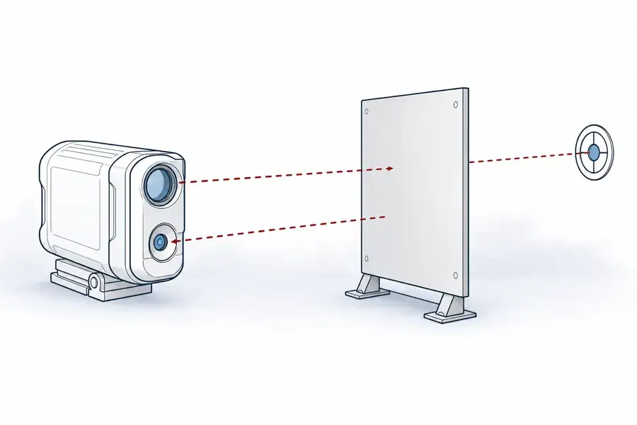
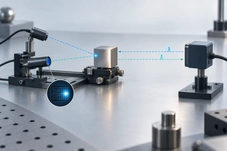
Typical pulsed time-of-flight concept. Dashed optical paths are conceptual encodings for non-visible light, not a specific Lumexis module architecture.
What an OEM should validate for a pulsed design
Start with the complete return path, not only the source. Define target material, reflectance, angle, working distance, ambient condition, and any protective window in the host enclosure. Then ask how the module defines a return, handles unexpected returns, and behaves when the target signal changes.
The host implementation deserves equal attention. Review supply behavior during transmit events, grounding, connector retention, mechanical datum surfaces, thermal path, the measurement trigger, and the data interface. A result recorded on an open bench is not yet evidence for the finished instrument.
How phase-shift rangefinders work
In a phase-shift system, the transmitted optical intensity is modulated at a known frequency. The receiver compares the returning modulation with a reference. The measured phase is converted to distance; for a single modulation frequency, the unambiguous interval is limited by the modulation period. The relationship is often expressed as distance = cφ/(4πf), where c is the speed of light, φ is the phase difference, and f is modulation frequency. It is a typical relationship, not a product specification. A peer-reviewed overview describes this indirect time-of-flight model.
The method can be well suited to a controlled distance interval where repeatable phase measurement is valuable. But it transfers complexity into modulation quality, demodulation, phase calibration, ambient-light rejection, optical cross-talk control, and ambiguity handling. A vendor should describe the frequency plan and the operating interval behind a stated result, rather than offering a distance number without conditions.
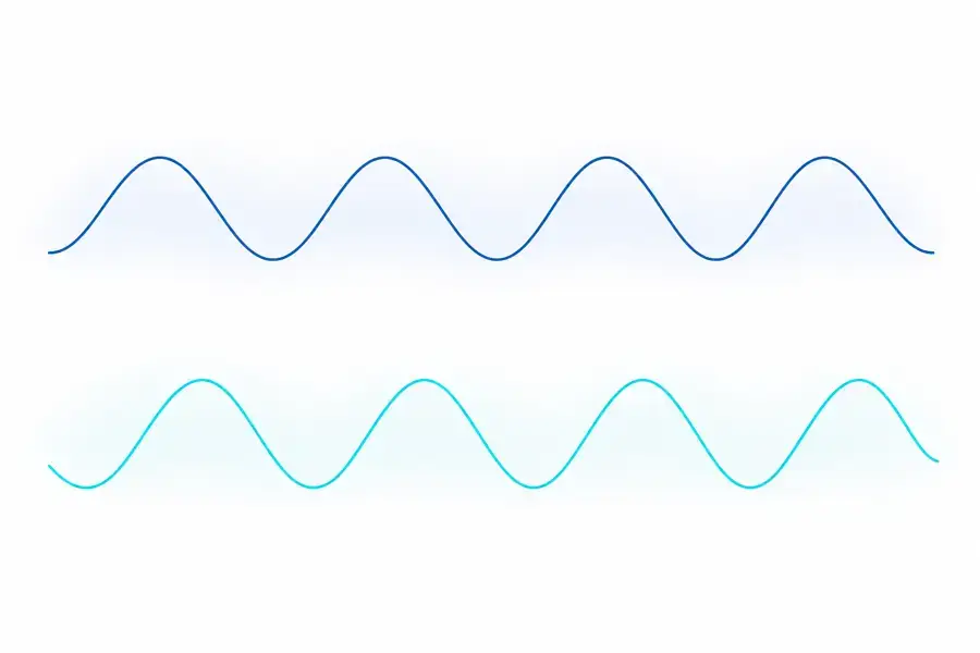
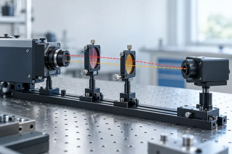
Conceptual phase relationship only. The waveform-like forms indicate relative delay and contain no measured data, frequency, or product-specific implementation.
Questions that expose phase-shift integration risk
Ask what resolves phase ambiguity, what target surfaces were used during validation, and how the system is calibrated over its operating temperature range. If the module will sit behind an optical window or share a housing with other light sources, evaluate the installed optical stack. Back reflections and internal scatter that appear minor on a bench can matter in a phase-sensitive measurement path.
Also define the result you need: repeatability, absolute error, update behavior, or response to changing target surfaces. These are related but distinct acceptance criteria. The datasheet should state the condition for every consequential number.
Phase shift vs pulsed laser rangefinder: comparison table
| Decision area | Pulsed time-of-flight | Phase-shift measurement |
|---|---|---|
| Distance derivation | Direct timing of a reflected pulse | Phase delay of a modulated return |
| Core electronics focus | Fast timing reference and return detection | Modulation, demodulation, phase calibration |
| Important validation risk | Return detection changes with signal conditions | Phase ambiguity and phase bias across conditions |
| Useful supplier evidence | Target-specific return tests and timing behavior | Frequency plan, ambiguity method, and calibrated interval |
| Host-integration focus | Optical return path, timing, power, and interface | Optical cross-talk, calibration stability, and reference integrity |
Do not read this table as a range ranking. Working-distance suitability depends on the architecture, optical design, detector, target, environment, and required result. A 2020 technical review similarly separates pulse-based direct ToF from phase-based indirect ToF instead of treating them as interchangeable variants. See the review.
A selection workflow that survives prototype testing
First, describe the measurement task in engineering terms: target set, smallest and largest distance, target angle, acceptance uncertainty, update behavior, host envelope, interface, and operating environment. The required test method should be written at the same time. It becomes the basis for comparing samples fairly.
Second, choose the architecture that makes the dominant constraint easier to manage. If broad return timing behavior and a directed measurement path dominate, a pulsed approach may fit naturally. If a bounded measurement interval and phase-based readout fit the instrument, phase shift may be appropriate. This is a system decision, not a shortcut based on a single parameter.
Third, qualify the assembled instrument. Include the host window, bezel, power supply, cable routing, mounting, and intended targets. Confirm behavior during the temperature range and background conditions that matter to the customer. The most useful evaluation record captures conditions as carefully as results.

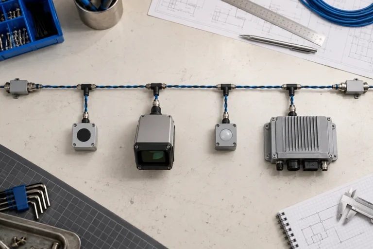
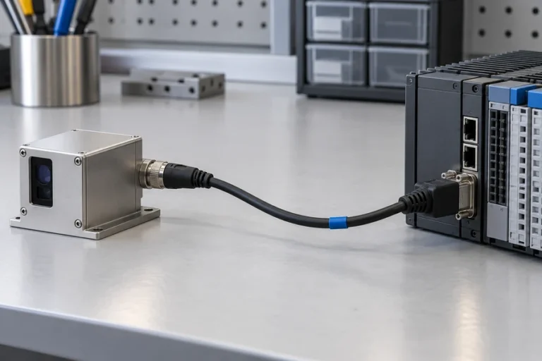
Conceptual civil-industrial integration context, not a customer installation or measured test setup.
What to look for in a rangefinder module supplier
The supplier should be able to discuss the measurement architecture at the level of your application, not merely repeat a headline range. Ask for the test conditions behind measured results, recommended host integration practices, change control, and a sample-to-production evaluation plan.
At Lumexis, we design and manufacture laser rangefinder modules for civil measurement, industrial inspection, and scientific instruments. Our team can work from target conditions and integration constraints through optical, electronic, mechanical, and validation trade-offs. Our technology capabilities describe the engineering disciplines behind that work, while our solutions page provides the broader application context.
Reliable production also needs controls beyond a finished-goods check. Incoming inspection, chip testing, assembly, optical alignment where applicable, aging screening, and final performance testing each provide a point to manage variation. For an OEM, that creates a more useful path from first sample to repeatable supply.
FAQ
Is phase shift more accurate than pulsed time-of-flight?
Not as a universal rule. Each method can be engineered for demanding measurement tasks, but the relevant result depends on the target, distance interval, optics, electronics, calibration, and test conditions. Compare the evidence at your intended operating point rather than comparing architecture names or unqualified headline values.
Why does a phase-shift rangefinder need ambiguity handling?
Phase is periodic. A given measured phase can correspond to more than one whole-cycle travel distance unless the system adds information, such as another modulation frequency or a controlled operating interval. Ask the supplier how ambiguity is resolved and what distance range the validation covers.
Can a pulsed rangefinder measure close targets?
It can be designed for particular distance intervals, but close-target behavior requires the full optical and electronic implementation to be evaluated. Receiver recovery, transmitter-to-receiver separation, stray light, timing extraction, and host-window reflections can all influence the result. Test the intended target geometry rather than assuming one architecture solves every interval.
What data should an OEM request during evaluation?
Request the target type, distance, target angle, ambient condition, temperature, supply condition, update behavior, measurement definition, and uncertainty method behind each result. Also review the host interface, mounting guidance, optical-window assumptions, traceability, and the proposed production acceptance test.
If you are choosing between phase-shift and pulsed laser rangefinders for an OEM program, contact our engineering team with your target conditions, mechanical envelope, interface, and validation requirements.
References
1. RP Photonics, “Distance Measurements With Lasers” — pulse and phase-shift measurement concepts. 2. Hamamatsu Photonics, “Measuring Distance With Light” — direct and indirect time-of-flight overview. 3. P. N. et al., “Pulse Based Time-of-Flight Range Sensing” — phase-based indirect time-of-flight relationship. 4. Comparison of Time-of-Flight and Phase-Shift TLS Intensity Data — measurement-method comparison.