








Choosing a wavelength late in a rangefinder program can force changes to the transmitter, receiver, optics, firmware, and qualification plan at once. The apparent shortcut is to compare two wavelength labels. The real decision is whether the whole instrument can meet its range, size, cost, and accessible-emission requirements together.
That is why a comparison based on a single claimed range or source power usually disappoints an OEM team. Target reflectance, receiver noise, aperture, pulse format, beam divergence, atmosphere, and processing all shape the result.
A 905nm vs 1535nm laser rangefinder decision is a system trade-off. A 905 nm architecture can align with mature silicon-detector ecosystems and compact semiconductor sources, while a 1535 nm architecture can use an erbium-glass source and an InGaAs-class receiver where the defined product’s accessible-emission review supports that route. Neither wavelength guarantees range, safety classification, or cost by itself.
For a 905nm vs 1535nm laser rangefinder evaluation, require both candidates to use the same target, range window, and test conditions before comparing them.
905nm vs 1535nm laser rangefinder: begin with the end requirement
Write the measurement requirement before selecting a source. State the target type and reflectance, minimum and maximum working distance, operating temperature, ambient-light condition, measurement rate, mechanical envelope, interface, and the way the finished instrument will be used. These inputs identify the architecture questions that a wavelength comparison must answer.
For example, a compact industrial distance instrument may prioritize receiver availability, low electrical load, and a modest optical envelope. A long-path measurement program may instead be constrained by the pulse-energy budget, receiver sensitivity, and the completed product’s accessible optical output. The right comparison starts with those constraints, not with a headline claim.
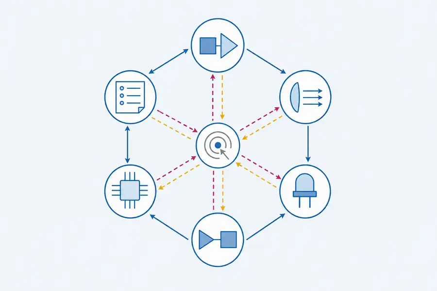
Caption: Conceptual system map only. Dashed paths show invisible wavelengths for explanation; the image is not a product design or a performance model.
What changes in the transmitter and receiver
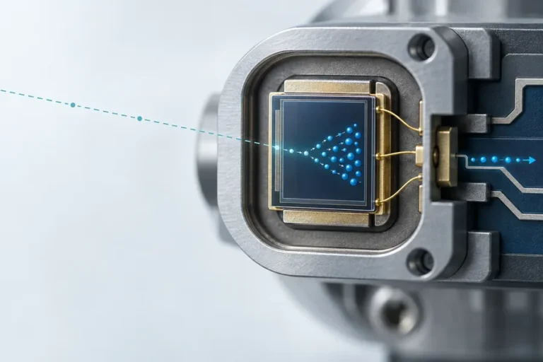
At 905 nm, silicon detector technologies are commonly available for sensing architectures. At wavelengths in the 1.5 µm region, silicon is generally not responsive, so the receiver path commonly moves to materials such as InGaAs. RP Photonics notes this receiver difference as an important system-cost and complexity consideration for sources beyond roughly 1.4 µm. That change can affect detector selection, front-end design, optical filtering, and the procurement plan.
The transmitter is also an architecture choice. A 905 nm rangefinder can use semiconductor-source approaches suited to the desired pulse and thermal design. A 1535 nm rangefinder can use an erbium-glass source; the gain-medium and pulse-generation route must still be evaluated at the intended repetition rate, temperature, and drive condition. Do not transfer a pulse-energy figure or a range result from a different transmitter design.
Receiver sensitivity should be discussed with the return path, not alone. The return depends on the target, transmit divergence, receiver aperture, optical losses, atmospheric path, timing method, and processing. See our guide to laser rangefinder module datasheets for the operating conditions that belong beside a performance figure.
Safety review belongs to the finished instrument
Wavelength matters because the eye interacts differently with different infrared regions. RP Photonics explains that light beyond approximately 1.4 µm is strongly absorbed in the cornea and lens before reaching the retina; it also cautions that this does not make a high-energy source harmless. Accessible output still depends on power or pulse energy, beam geometry, divergence, exposure conditions, and the finished optical product.
For an OEM, the practical action is to request controlled evidence for the exact configuration. Check the apertures, windows, transmit optics, operating modes, service access, and host-instrument changes. A module description is useful evidence, but it is not a substitute for a review of the finished product boundary. Our laser-ranging solutions are approached as optical, electronic, and mechanical system work rather than a source-only selection.
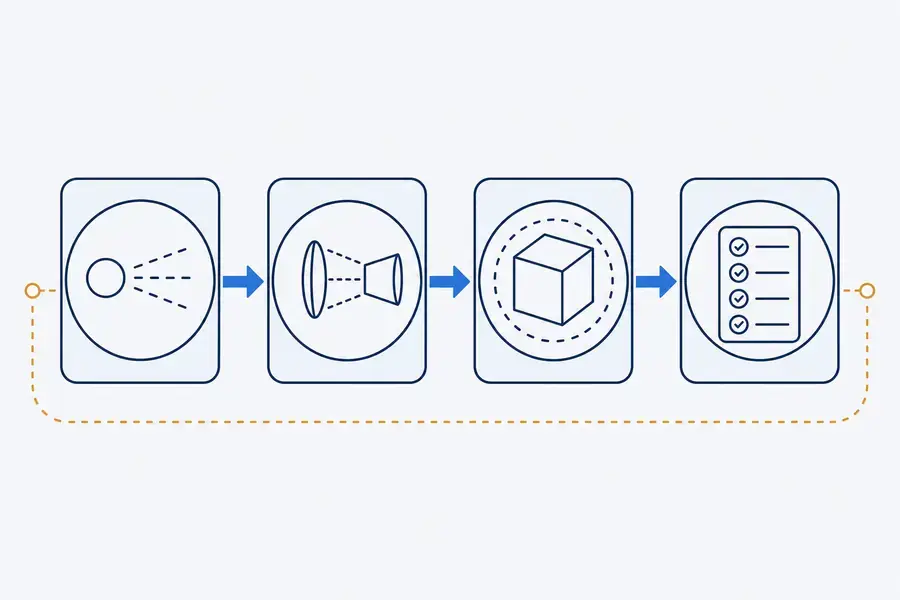
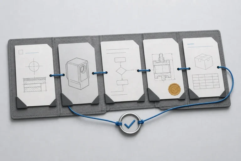
Caption: Conceptual review chain only. It explains a complete-product assessment boundary and does not show a certification or a specific product.
Compare cost and integration risk, not just component price
A receiver family can change more than the detector bill of materials. It can introduce a different biasing, amplification, filtering, calibration, and supply-chain profile. A source architecture can change the drive electronics, thermal path, packaging, and production screening needed for repeatable output. Those effects are why a lower component price is not automatically a lower instrument cost.
Ask each supplier to define the operating point behind its claim: temperature, repetition rate, drive condition, target condition, and measurement method. Then ask what changes are controlled across production. Incoming inspection, chip test, die bonding, optical alignment, burn-in, and final testing all matter when an OEM needs units that behave consistently over time.
| Decision question | 905 nm path to review | 1535 nm path to review | |—|—|—| | Receiver | Silicon-compatible detector and front-end choices | InGaAs-class receiver choice, noise, bias, and availability | | Transmitter | Pulse format, thermal path, divergence, and drive electronics | Erbium-glass source architecture, pulse conditions, and thermal behavior | | Finished-product review | Accessible output, apertures, and use conditions | The same completed-product review; wavelength does not replace it | | Supply decision | Source and receiver maturity at the required operating point | Receiver and source availability, qualification, and change control |
How we frame an OEM evaluation
At Lumexis, we begin by separating source parameters from instrument performance. Our team can discuss optical and optomechanical design, electronics and firmware, weak-signal ranging logic, thermal management, and the manufacturing checks that support a defined build. That gives the buyer a path to compare architectures with the same target, test method, and integration boundary.
Use our technology overview to frame the engineering conversation, then bring the real constraints: target type, range window, mounting, interface, rate, ambient condition, and production quantity. A compact module is valuable only when it fits the host system and the verification plan.
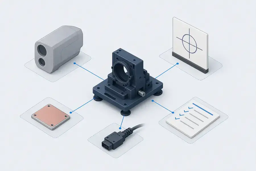
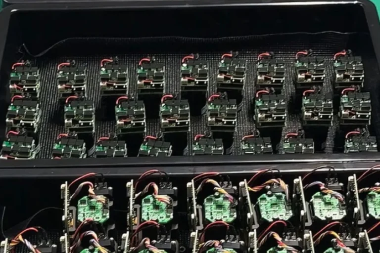
Caption: Conceptual OEM integration planning view. It is not a Lumexis product, facility, test setup, or customer deployment.
FAQ
Is 1535 nm always the better choice for long range?
No. Long-range capability depends on the complete link budget and measurement conditions, including target reflectance, transmit and receive optics, detector behavior, atmosphere, timing, and signal processing. A 1535 nm architecture can be appropriate for some demanding designs, but it should be compared against the actual range requirement and integration cost.
Is 905 nm automatically lower cost?
Not automatically. The 905 nm ecosystem can offer mature source and silicon-receiver options, but total cost also includes optics, electronics, production yield, qualification, and the field-risk cost of the finished instrument. Compare a controlled configuration, not a component price in isolation.
Does 1535 nm make a rangefinder compliant by default?
No. The wavelength gives useful optical-hazard context, but classification depends on the accessible emission from the finished configuration and its defined use conditions. Verify the controlled evidence for the actual instrument, including optics, apertures, and operating modes.
Which detector family is used around 1535 nm?
Silicon detectors do not generally cover the 1.5 µm region, so InGaAs-class receivers are commonly considered. Their selection should include responsivity, noise, front-end design, availability, and the operating point. Do not infer a system result from detector material alone.
What should be in an OEM RFQ?
Include target condition, range window, measurement rate, temperature, power budget, optical envelope, interface, host-instrument optics, and the expected production change-control process. Ask for the test method and the configuration behind each claimed value.
For a structured comparison of your rangefinder options, contact our engineers with the system constraints that determine the actual design trade-off.