





A rangefinder datasheet can state an impressive maximum distance while leaving the test boundary vague. If the target, background light, atmosphere, measurement mode, and success rule are missing, your prototype may fall short even though neither the module nor the datasheet is technically wrong.
The fix is to treat range as a conditional performance result, not a property that exists independently of the test. A disciplined test makes supplier comparisons fair and gives your design team evidence it can carry into system verification.
A useful laser rangefinder range test defines a valid return, controls target and environmental conditions, establishes a traceable reference distance, repeats each condition, and brackets the stable detection boundary. Report detection probability separately from distance error, and record the exact hardware, firmware, power, measurement cadence, alignment, and host optics used.
A range claim is a condition set, not a standalone distance
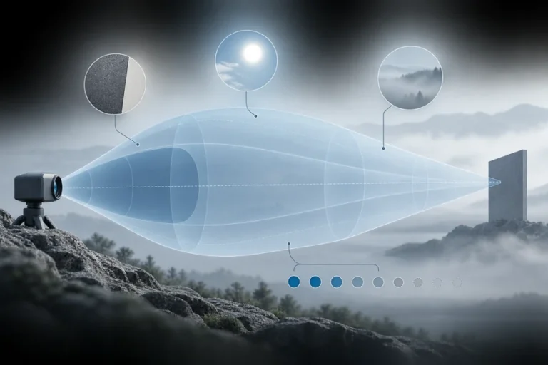
“Maximum range” should immediately prompt a second question: under which conditions? A strong return from a large, normal-incidence panel in low background light does not predict the same boundary as a small, angled, low-return target under bright outdoor illumination. The factors that limit laser rangefinder maximum range act together, so changing one can move the detection boundary.
ISO 16331-1:2017 was written for handheld laser distance meters, not as a universal qualification standard for every OEM pulsed module. Its measurement discipline is still useful: range and accuracy specifications need conditions and a defined method for checking compliance. The standard explicitly addresses target reflectivity, background illumination, component temperature, atmosphere, measurement uncertainty, and a range-compliance procedure.
Before comparing two datasheets, capture the complete claim:
| Record field | What to write down | Why it matters |
|---|---|---|
| Distance claim | Value, units, minimum/typical/guaranteed wording | These statements carry different acceptance meaning |
| Target | Reflectance at the operating wavelength, size, surface, angle | The receiver only sees the returned optical energy |
| Geometry | Footprint coverage, aim point, alignment, reference datum | Partial coverage can mix target and background returns |
| Environment | Background illuminance, visibility, weather, temperature | Noise and two-way transmission change with conditions |
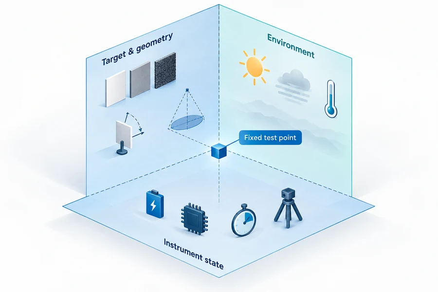
| Instrument state | Hardware, firmware, power, mode, cadence, warm-up | Processing and operating point affect the result |
| Valid-return rule | Error window, confidence/status fields, exclusions | A single reported number is not automatically a valid hit |
| Repetitions | Trials per point and aggregation method | Reliability cannot be inferred from one success |
Target percentages also need context. Our guide to rangefinder target reflectivity explains why a reflectance value is not the same thing as probability of detection and why visible color is not a substitute for spectral characterization.
Build the laser rangefinder range test before data collection
Write the protocol before powering the unit. Otherwise, it is easy to adjust aim, change averaging, discard inconvenient returns, or stop after a favorable reading. Those choices may be reasonable during exploration, but they cannot remain implicit in an acceptance test.
Define a valid return first
State what counts as valid. At minimum, define the permitted distance-error window, required status or confidence field, treatment of zero/invalid codes, and handling of a plausible but incorrect surface. If the module can report first, last, or strongest return, freeze that selection too.
A valid-return rule should be independent of the expected result. For example, “within the agreed error band of the reference and free of an invalid status” is testable. “Looks reasonable” is not.
Establish the reference distance
The reference must be better known than the tolerance you are trying to verify. Record how the reference distance is established, its datum, its uncertainty, and any environmental correction that is material at the tested distance. A surveyed baseline, calibrated reference instrument, or documented facility can work; the method depends on the required uncertainty.
Do not mix the module’s own reading into the reference. That makes the test circular.
Freeze the instrument and host state
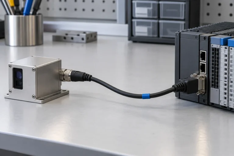
Record serial identity, hardware and firmware revisions, supply voltage at the module, cable and interface, measurement cadence, averaging or filtering, warm-up, alignment, window, mounting, and host commands. A bare-module result and an enclosed-system result are different configurations because the host can add loss, stray return, thermal shift, electrical noise, or pointing error.
For the wider incoming, environmental, and production sequence, use our laser rangefinder module test guide alongside this range-boundary method.
Find the stable boundary instead of recording the farthest hit
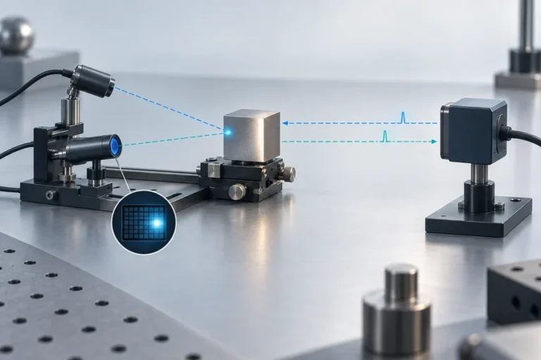
The farthest number seen on a screen is an observation, not a verified limit. A practical boundary search begins at a distance expected to pass, approaches the transition in coarse steps, then uses finer fixed points around the change from consistent valid returns to frequent invalid or out-of-window results.
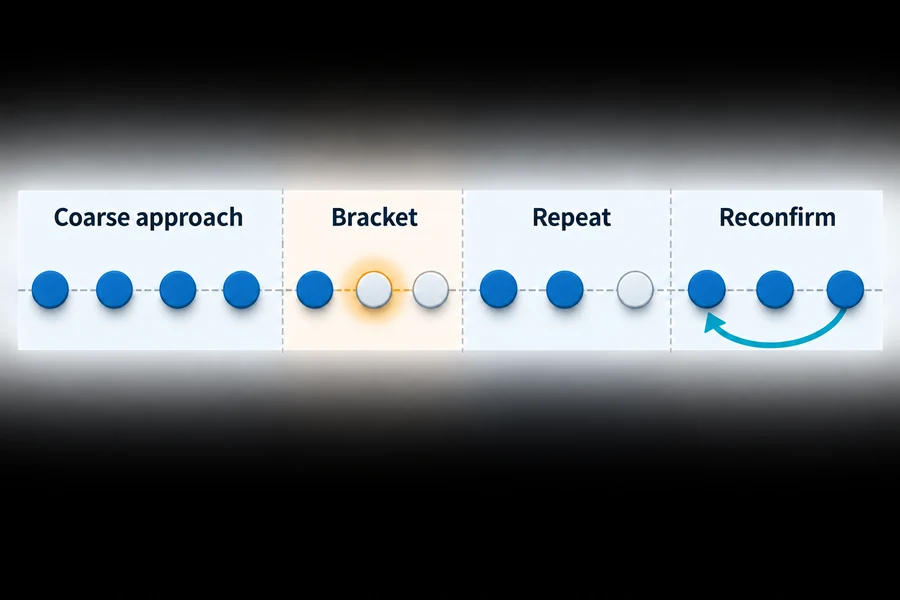
Use the same aim point and fixture at every trial. At each fixed distance, collect the planned number of returns without changing settings. Continue beyond the first failure so you can distinguish a random invalid result from a true transition. Then return to a nearer passing point. That final reconfirmation can expose warm-up drift, alignment movement, changing background light, or an unstable setup.
Set the boundary rule before the test. It might be the farthest point that meets the required valid-return fraction and error limit, followed by a failed point beyond it. The exact probability, trial count, step size, and margin must come from your system requirement. They should not be invented after the data is visible.
Run the sequence in both approach directions when hysteresis, adaptive thresholds, automatic gain, or thermal state may matter. Preserve every trial, including invalid and false returns. Cherry-picking successful samples produces a demonstration, not a qualification result.
Separate target, background, atmosphere, and temperature effects
A single outdoor test can be realistic but diagnostically weak. If performance changes, you may not know whether the cause was target angle, footprint spill, sunlight, visibility, temperature, supply behavior, or alignment. Establish a controlled baseline first, vary one factor at a time, and only then run the combined application condition.
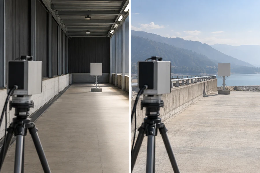
Target and footprint
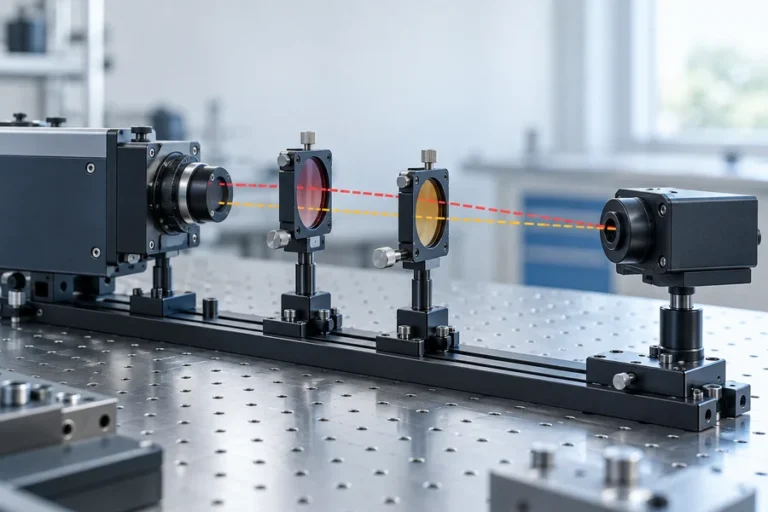
Use a characterized target when the specification names reflectance. Record its data at the operating wavelength, not only a visible-light value. Fix the target dimensions, surface orientation, and aim point. If the beam footprint becomes larger than the target, the receiver may collect a composite of the intended surface and its background.
Surface finish matters as well as nominal reflectance. A diffuse surface spreads return energy over angle, while a glossy surface can direct most energy away from a colocated receiver when tilted. A high nominal reflectance is therefore not a guarantee of a strong captured return at every geometry.
Background light and atmosphere
Measure or classify background illumination at the receiver’s view of the target, not only at the operator. Test the orientation that matters to the application. Bright background can raise the noise floor even when the target itself has not changed.
Atmospheric transmission acts on the outward and return paths. Record visibility and relevant weather rather than labeling a day simply “clear.” If application conditions include haze or precipitation, characterize them separately from the controlled baseline. Our laser-ranging solution places this verification work in the broader civil, industrial, and scientific system context.
Temperature, warm-up, and supply
Temperature can affect the source, receiver, timing electronics, alignment, and compensation. Stabilize at each planned temperature, record the soak logic, and repeat the same distance points. Also log voltage at the module during ranging; a bench supply display does not reveal every cable drop or pulse-related disturbance at the load.
Do not claim a full environmental operating range from one room-temperature distance test. Likewise, do not use a chamber result to stand in for an outdoor atmosphere test. The two experiments answer different questions.
Report detection probability and distance error separately
For one fixed condition, a simple observed valid-return fraction is:
Pdet = Nvalid / Ntotal
Here, Nvalid is the number of returns that meet the predeclared rule, and Ntotal is the number of commanded trials included by the protocol. This fraction describes the observed test sequence; it is not a universal probability for every target and environment. The confidence attached to it depends on sample size and the statistical method used.
Distance error is a separate result. Preserve signed error when bias matters, absolute error when checking a limit, and the spread of repeated readings. An average alone can hide two clusters, intermittent false returns, or a temperature-dependent shift. Report invalid commands and plausible-but-wrong returns explicitly rather than removing them from the denominator.
Keep these three percentages distinct:
- target reflectance, an optical property under stated wavelength and geometry;
- valid-return fraction, an observed outcome under the test rule;
- confidence level or interval, a statistical statement about the estimate.
Mixing them makes a report look precise while leaving its meaning unclear.
Turn the results into a supplier-comparison packet
A useful evidence packet lets another engineer recreate the result. Include the approved protocol, setup drawing or photographs, reference method and uncertainty, raw trial log, environmental record, target certificate or characterization, configuration list, acceptance calculation, deviations, and test revision. Link the unit and data to serial or lot identity where appropriate.
For supplier comparison, normalize claims to the closest shared condition. If two suppliers use different targets, success rules, or settings, show the difference rather than forcing their numbers into one ranking. Ask for the missing conditions and rerun the same protocol on both units when the decision matters.
LUMEXIS designs and manufactures laser rangefinder modules and laser sources for measurement, sensing, and scientific systems. Our Wuxi engineering and commercial office works with the 14,000-square-meter Taizhou manufacturing base, where cleanroom assembly, temperature cycling, burn-in or aging screening, and final performance testing support a configuration-controlled handoff.
Our applications engineers can assist with selection, integration, validation, and troubleshooting through engineering services. Standard products can ship within three days; custom configurations and private-label programs follow project-specific requirements and lead times.
Frequently asked questions
How many readings are enough for a range test?
There is no universal number. Choose the sample size from the required valid-return rate, the confidence needed for the decision, test time, and the risk of an incorrect pass. A small exploratory run can locate the boundary, but a release criterion needs a documented statistical rationale and consistent treatment of invalid and false returns.
Can a reflective panel prove field range?
It can verify performance under that panel’s reflectance, size, angle, wavelength, and environment. It does not by itself prove range to smaller, angled, wet, glossy, or spectrally different application targets. Use the panel for a repeatable baseline, then add representative targets without changing the baseline result’s label.
Should the test start indoors or outdoors?
Start with the most controlled setup that can verify the instrument and protocol. Indoor or sheltered baselines make target, distance, power, and repeat logic easier to isolate. Add outdoor background and atmospheric conditions afterward. The final acceptance matrix should include the combined conditions that actually drive the system requirement.
Why does range drop in bright background light?
Background photons add receiver noise and can reduce the margin between a returned pulse and the detection threshold. The effect depends on wavelength, receiver bandwidth and filtering, optics, target direction, processing, and exposure or measurement mode. Record illumination and geometry rather than assuming every sunny condition is equivalent.
Does passing the module test guarantee host-system range?
No. A host window, enclosure reflection, alignment tolerance, mounting shift, supply disturbance, heat path, cable route, or firmware command can change the operating condition. Repeat the critical range points with the final optical, mechanical, electrical, and software configuration, and preserve the configuration in the report.
References
- International Organization for Standardization, ISO 16331-1:2017 — Performance of handheld laser distance meters.
- International Organization for Standardization, ISO 16331-1:2017 Online Browsing Platform preview.
- RIEGL, Operation of a Pulsed Laser Distance Meter.
- Zhang et al., The Short-Range, High-Accuracy Compact Pulsed Laser Ranging System, Sensors, 2022.
Preparing an OEM qualification review? Send our applications engineers the required distance, target material or reflectance, target size and angle, background and atmosphere, temperature, update rate, valid-return rule, mechanical envelope, interface, and expected volume. We can recommend a standard module, confirm availability, or scope a custom configuration and validation plan.