




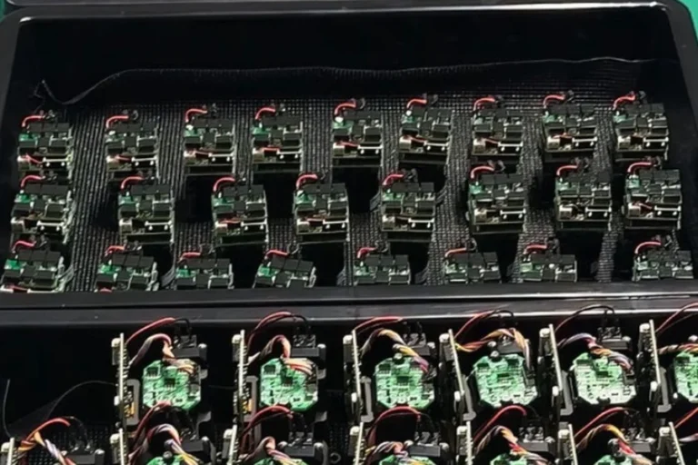





Most laser problems that show up late in a program trace back to the pump, not the resonator. Output drifts as the baseplate warms. Efficiency looks fine on the bench and disappears at −30 °C. A design that hit spec with one batch of diodes misses it with the next.
The resonator usually gets the attention because that is where the physics feels interesting. The pump is where the heat, the drift, and the failure modes live.
This article explains what laser pumping actually does, how the main pumping architectures differ, and which pump-source decisions determine whether a laser holds its specification across temperature, time, and production volume.
Table of Contents
LUMEXIS
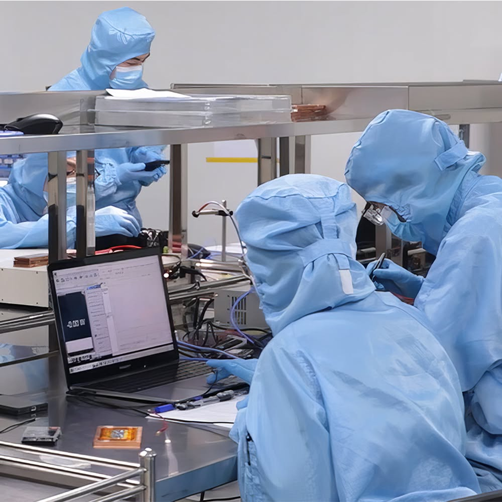
Cleanroom for laser module assembly
Laser pumping is the process of injecting energy into a gain medium to create population inversion — more atoms in an excited state than in the lower state — so stimulated emission can produce optical gain. Energy is delivered optically (diodes, flashlamps), electrically (current through a semiconductor or gas), or chemically. Without pumping, there is no laser.
The physics, in the amount of detail that actually matters
In thermal equilibrium, almost every atom in a material sits in its ground state. Send light through it and the light gets absorbed. That is normal, and it is the opposite of what a laser needs.
Pumping inverts that. Energy pushes atoms into an excited state faster than they decay, until more of them are excited than not. Once that inversion exists, an incoming photon of the right energy is more likely to stimulate an excited atom into emitting an identical photon than it is to be absorbed. Light entering the medium leaves amplified. That is optical gain, and everything else in a laser — mirrors, Q-switch, output coupler — is machinery built around it.
Two structural details govern how hard the inversion is to achieve.
A four-level gain medium drops the atom into a lower laser level that is essentially empty at room temperature, then quickly dumps it to the ground state. Because the lower level stays empty, inversion happens as soon as a tiny fraction of the ions are excited. Nd:YAG at 1064 nm works this way, which is a large part of why it is so forgiving.
A quasi-three-level medium has a lower laser level that is thermally populated. You are fighting reabsorption of your own output, so a substantial fraction of the ions must be excited before you see any net gain at all. Ytterbium and erbium systems often behave this way. They demand higher pump intensity and much tighter thermal management, and they punish an underspecified pump source far more than a four-level design does.
This distinction is worth carrying into a design review, because it determines how much pump margin you need before the laser will start at all at the cold end of your operating range.
Between those two sits the classic three-level system, worth knowing because it is where the field started. In ruby, a flashlamp lifts chromium ions into a broad absorption band, from which they drop non-radiatively into a metastable level in roughly 10−8 s. That level then holds them for about 10−3 s — five orders of magnitude longer — so population piles up there until it exceeds the ground state and 694.3 nm output becomes possible. The ratio between those two timescales is the entire trick, and it returns later in this article as the thing that decides how much energy a Q-switched laser can store.
A pump source is a system, not a component
Engineers specify a pump as a wavelength and a power. Suppliers ship an assembly. Between those two statements sit four subsystems, and any one of them can be the thing that quietly costs you ten percent of your output.
The drive electronics. A diode’s wavelength, output power and lifetime all follow its junction current and temperature. A driver with poor current regulation, visible ripple, or an uncontrolled turn-on moves the emission wavelength during the pulse and shortens diode life through transients. In quasi-continuous operation the current rise time directly shapes the pump pulse and therefore the stored energy. The driver is not an accessory to the pump source. It is part of it.
The emitter. Single emitter, bar, or stack — and, inside a fibre-coupled module, the beam-shaping optics that turn a wildly asymmetric diode output into something a fibre will actually accept.
The coupling path. Fast-axis collimation, slow-axis collimation, focusing, sometimes polarisation and wavelength multiplexing, and the fibre itself. Every surface here carries a transmission loss and a thermal coefficient.
The thermal path. Submount, solder, baseplate, interface material, cold plate. Junction temperature is what the physics responds to; case temperature is what the datasheet quotes. The difference between them is a property of this stack, not of the diode.
A useful discipline in a design review is to ask which of these four you are buying and which you are being left to build. A bare diode is cheap because three of the four become your problem. A characterised fibre-coupled module costs more because the supplier has already closed the loop on all four and can state delivered power at the fibre end across your temperature window.
Optical, electrical, chemical pumping – What is the difference
There are three ways to deliver pump energy, and in practice most engineers only meet two.
Optical pumping uses light matched to the gain medium’s absorption bands. Flashlamps did this for decades and still appear in high-energy pulsed systems, but they are broadband, inefficient, and hot: most of the lamp’s output falls outside the absorption band and turns into waste heat in the crystal. Laser diodes replaced them almost everywhere because diode emission can be placed directly on an absorption peak. That single change — spectral matching — is responsible for most of the efficiency gain in solid-state lasers over the past thirty years.
Electrical pumping drives current directly through the gain medium. Gas lasers use a discharge. Semiconductor diode lasers use current across a p-n junction, where recombination produces photons directly. Diode lasers are electrically pumped devices that are themselves used as optical pumps for other lasers, which is a genuinely useful thing to keep straight.
Chemical pumping extracts inversion from a reaction, typically combustion of hydrogen and fluorine. It scales to very high power without an electrical supply, which is why it exists at all, but it is rare and confined to specialized systems.
For anything you are likely to design into a product, the question is not which of the three to use. It is which pump diode, at which wavelength, in which geometry.
Put the methods side by side and the trade stops being subtle.
| Pump method | Electrical→optical efficiency | Typical lifetime | Spectral match | Where it still makes sense |
|---|---|---|---|---|
| Flashlamp | ~1–5% into the absorption band | 107–108 shots | Broadband; most of it wasted as heat | Very high pulse energy, cost-driven or service-accessible systems |
| Diode, direct (end or side) | 45–65% | >20,000 h typical | Narrow, placed on the absorption peak | Most DPSS products: marking, ranging, micromachining |
| Diode, fibre-coupled | 40–55% after coupling | >20,000 h typical | Narrow, plus flexible delivery | Fibre lasers and amplifiers; pump located away from the gain medium |
| Gas discharge (DC or RF) | 5–20% | Tube-life limited | Not applicable — direct excitation | CO2, excimer, HeNe |
| Chemical | No electrical input | Consumable-limited | Not applicable | Very high power where no power supply exists |
Two footnotes on the methods most engineers never touch. Gas-discharge pumping splits into continuous glow discharge (HeNe, sealed CO2), radio-frequency excitation, which produces a more uniform plasma at higher gas pressure, and pulsed discharge with ultraviolet pre-ionisation — the technique that lets excimer and TEA CO2 lasers fire as a uniform volume discharge instead of collapsing into an arc. Chemical pumping likewise splits in two: combustion-driven HF and DF systems, and photodissociation lasers, where ultraviolet light cracks an alkyl iodide such as CF3I to leave excited iodine atoms emitting at 1.315 µm. Both exist because they scale to power levels a wall socket cannot supply.
What is Fiber-Coupled Pumping?
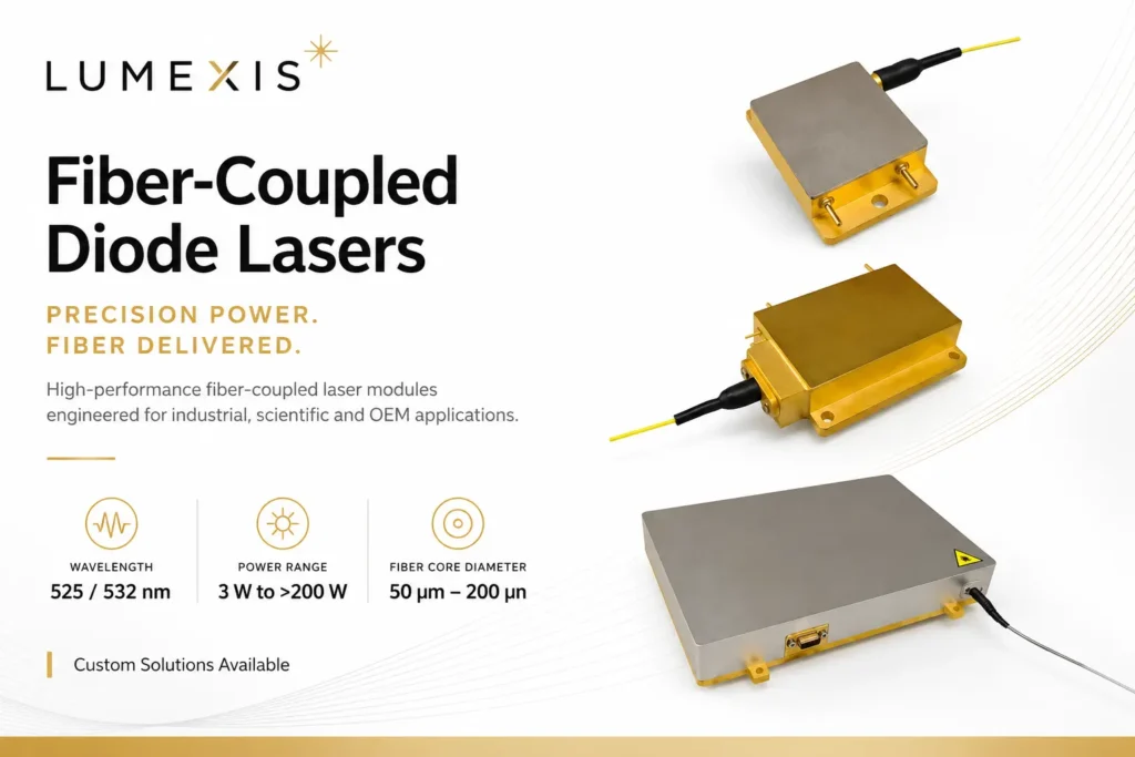
Fiber-coupled pumping involves coupling the outputs of multiple laser diodes into a single optical fiber via a fiber combiner to achieve high-brightness pumping. This approach is suitable for high-power fiber lasers and amplifiers, enabling laser output at the kilowatt level or higher.
The advantages of fiber-coupled pumping include high flexibility and simplified thermal management; the pump source can be separated from the gain fiber, thereby reducing the laser’s footprint while enhancing system stability and reliability. Furthermore, techniques such as wavelength locking and spectral beam combining can be employed to further increase pump brightness and achieve even higher output power.
Brightness, étendue, and why fibre coupling is the hard part
A diode emitter is a poor optical object. Its output is violently divergent in the fast axis and nearly diffraction-limited there, then much less divergent but spatially broad in the slow axis. You cannot fix that by focusing harder. The product of spot size and divergence angle — étendue, or its inverse, brightness — is conserved through any passive optical system. You can trade beam size against angle. You cannot reduce the product.
Every element inside a fibre-coupled module exists to work within that constraint. Fast-axis collimation with a short-focal-length cylindrical microlens tames the divergent axis first, because uncollimated fast-axis light is exactly what overfills a fibre’s numerical aperture. Slow-axis collimation and beam shaping — step mirrors, rotating prism arrays — then redistribute the beam so both axes present comparable étendue. Only after that does focusing into a 105, 135 or 200 µm core at 0.22 NA become possible without discarding half the power at the fibre face.
Once one emitter is in a fibre, brightness scaling continues by combining beams in dimensions that cost no étendue: polarisation combining, which merges two orthogonal states through one aperture; spectral combining, which merges several wavelengths through a dichroic or a grating; and, in fibre, an (N+1)×1 tapered fibre bundle that merges several multimode pump fibres around a signal core.
Volume Bragg grating wavelength locking belongs on this list too. Narrowing a diode from a 3–4 nm free-running spectrum to well under 1 nm and pinning it against temperature is not only a drift fix — it is what makes spectral combining possible at all, and it is what lets you use a narrow absorption feature such as the 976 nm ytterbium peak that a free-running diode would simply walk off.
This is where a supplier’s process either shows up or does not. Automated active alignment during fibre coupling, and verification of delivered power at the connector rather than at the chip, is the whole difference between a datasheet number and a system number. Our manufacturing and test flow is built around that distinction.
End pumping versus side pumping
Where you inject the pump light changes what the laser is good at.
End pumping sends the pump in along the resonator axis, usually through a dichroic mirror. Because the pump volume can be shaped to overlap the resonator mode closely, conversion efficiency is high and the output beam quality is excellent. The cost is that the pump beam itself must be good — you are focusing it into a small volume, so brightness matters, and thermal load concentrates in a short length of crystal. Thermal lensing shows up early.
Side pumping fires diode bars radially into the rod. Pump beam quality barely matters, so you can use cheap, high-power bars and scale to multiwatt and higher output. The trade is a less uniform overlap with the resonator mode, which costs efficiency and beam quality.
Cladding pumping is the fiber-laser equivalent and deserves separate mention. Pump light is launched into a large multimode inner cladding rather than the small doped core. It propagates along the fiber, crossing the core repeatedly and being absorbed gradually over meters. This is what makes high-power fiber lasers practical: it decouples pump brightness from the requirement to hit a tiny core, letting relatively modest fiber-coupled diodes drive a single-mode output. It is the architecture behind most 976 nm-pumped ytterbium and erbium-ytterbium systems, including the 1.5 µm sources used in eye-safe LiDAR.
Good side-pumped heads work considerably harder than that description suggests. A common arrangement surrounds the rod with three diode modules at 120° and encloses it in a glass tube whose outer surface is coated high-reflecting at the pump wavelength everywhere except three narrow anti-reflection stripes where the modules inject. The result is a closed pump cavity: light that misses the crystal on its first pass is reflected back and forth until it is absorbed, and because it then arrives from three directions after multiple bounces, the gain distribution across the rod cross-section comes out far more uniform than three discrete beams would imply. Uniform gain is what keeps the thermal lens symmetric, which is what keeps the output beam round.
Quantum defect: the heat you cannot design away
Pump a laser at 808 nm and extract at 1064 nm, and the energy difference between those photons does not vanish. It becomes heat in the crystal. That fraction is the quantum defect, and it sets a hard floor on thermal load no matter how good your optics are.
At 808 nm into 1064 nm, roughly a quarter of every pumped photon’s energy is lost this way. It is the dominant heat source in a well-built DPSS laser, and heat is what drives thermal lensing, stress birefringence, and eventually crystal fracture.
This is why longer pump wavelengths became interesting. Pumping Nd:YAG at 885 or 888 nm instead of 808 nm cuts the quantum defect by more than half, with a corresponding drop in heat generation. There is a catch, and it is instructive: neodymium’s absorption is much weaker at 880 nm than at 808 nm. Weaker absorption means the pump penetrates further, so you need a longer crystal — 30 mm rather than the 8 mm or less typical of 808 nm designs. In exchange you spread the heat over a longer volume, which is exactly what you wanted.
At 888 nm there is a further benefit worth knowing about. Absorption becomes nearly polarization-insensitive, which removes the need for tight wavelength locking and aggressive temperature control on the pump diodes. For a field-deployed system, dropping a TEC and its control loop is a meaningful reduction in power draw, volume, and failure modes.
That is the shape of most real pumping decisions. There is rarely a free improvement — there is a trade you either make deliberately or discover during qualification.
This family of approaches has a name worth using, because it is what the literature and most datasheets call it: in-band or resonant pumping — depositing pump energy directly into the upper laser level rather than into a higher band that then relaxes into it. Pumping ytterbium at 976 nm to emit at 1030 nm leaves a quantum defect near 5%, roughly a fifth of what 808 nm into 1064 nm costs.
Thulium at 793 nm is the case that breaks the arithmetic in a useful direction. The raw photon-energy difference to 2 µm output looks catastrophic, close to 60%. But thulium exhibits cross-relaxation: one absorbed pump photon can end up exciting two ions, approaching 200% quantum efficiency, which brings the effective thermal load down to roughly 18%. Quantum defect computed from wavelengths alone is a first-order estimate. Before you accept it, check whether your gain medium has an energy-transfer mechanism that changes the answer — 793 nm pump sources exist precisely because it does here.
Pump wavelength quick reference
Most of the pumping decision collapses into one table: which wavelengths carry commercial solid-state and fibre lasers, what each is for, and roughly what each costs you in heat.
| Pump wavelength | Gain medium | Typical output | Approx. quantum defect | Why you would choose it |
|---|---|---|---|---|
| 790 / 792 / 793 nm | Tm, Tm:Ho | 1.9–2.1 µm | ~59% raw, ~18% effective | Cross-relaxation nearly doubles quantum efficiency; 2 µm medical and sensing sources |
| 808 nm | Nd:YAG, Nd:YVO4 | 1064 nm | 24.1% | Strongest Nd absorption, shortest crystal, deepest and cheapest supply chain |
| 878.6 nm | Nd:YVO4 | 1064 nm | 17.4% | In-band pumping; requires a wavelength-locked diode |
| 885 nm | Nd:YAG | 1064 nm | 16.8% | In-band; markedly less heat, at the cost of a longer crystal |
| 888 nm | Nd:YVO4 | 1064 nm | 16.5% | Absorption is nearly polarisation-independent — the most tolerant in-band option, and TEC-friendly |
| 915 nm | Yb-doped fibre | 1070 nm | 14.5% | Broad, flat absorption; drift-tolerant and needs no wavelength locking |
| 976 nm | Yb and Er:Yb fibre | 1030–1070 nm; 1535–1550 nm | 5.2% (1030), 8.8% (1070), 36.4% (1535) | Strongest absorption per unit length, shortest fibre — but the peak is narrow and needs stabilisation |
| 525 nm | Ti:sapphire, alexandrite, dyes and fluorophores | Tunable / visible | Application-dependent | Direct green pumping and fluorescence excitation |
The pattern is consistent, and it is the single most useful thing to carry out of this table: the wavelengths that generate the least heat are the ones with the weakest, narrowest absorption, so they demand a longer crystal or tighter wavelength control in exchange. We build fibre-coupled pump sources across all of these bands, and the trade between thermal load and pump-source discipline is worth settling at the concept stage rather than during qualification.
Fluorescence lifetime, energy storage, and pump duty cycle
An excited ion does not wait indefinitely. The upper-level fluorescence lifetime is the average time it stays excited before decaying spontaneously, and it settles two commercially important questions: how much energy a Q-switched laser can store, and how long your pump pulse should be.
| Gain medium | Upper-level lifetime | What that means in practice |
|---|---|---|
| Nd:YVO4 | 90–100 µs | High gain, poor storage — suits CW and high-repetition-rate operation |
| Nd:YAG | ~230 µs | The general-purpose compromise; standard for Q-switched marking and ranging |
| Nd:YLF | ~480 µs | Long storage, high pulse energy at lower repetition rate |
| Yb-doped fibre | ~800 µs – 1 ms | Very high storage; also why Yb amplifiers tolerate gentle pumping |
| Er:glass | Milliseconds | Exceptional storage — the basis of compact eye-safe 1535 nm transmitters |
Nd:YVO4 and Nd:YAG make the trade concrete. Vanadate’s emission cross-section is roughly five times that of YAG, which is why it lases at lower threshold and higher gain. But cross-section and lifetime pull in opposite directions: the same property that gives vanadate its gain drains the upper level in under 100 µs. YAG holds population longer and therefore yields more energy per Q-switched pulse.
The rule that follows is blunt: pumping for much longer than the upper-level lifetime does not store more energy. It just heats the crystal. Which is why pump duty cycle is a specification and not a detail:
- CW pumping — constant current, steady thermal load, stable thermal lens. Correct for continuous output and for repetition rates high enough that the thermal state never really changes.
- QCW pumping — the pump runs for a few hundred microseconds around each output pulse, then switches off. Because the diode dissipates during only a small fraction of the cycle, it can be driven to peak currents several times its CW rating, delivering far higher peak pump power from the same package while average thermal load stays low. The pump pulse should be on the order of the upper-level lifetime; longer buys nothing.
- Pulsed and burst modes — everything else, usually dictated by an application duty cycle rather than by the gain medium.
For a battery-powered rangefinder firing a few pulses per second, QCW is not an optimisation — it is the reason the product can exist at all. Er:glass holds its inversion for milliseconds, so a modest diode can pump it slowly and a Q-switch can dump the result as a single high-peak-power 1535 nm pulse: eye-safe, and bright enough for kilometre-class ranging from a handheld or UAV-mounted head. The same logic scales up in erbium-doped fibre for 1.5 µm LiDAR sources.
A datasheet that quotes only CW power tells you nothing about QCW capability. Ask for peak current rating, maximum pulse width and duty-cycle limit together — those three numbers, not the CW figure, decide what pulse energy you can build.
What actually breaks: wavelength drift and thermal management
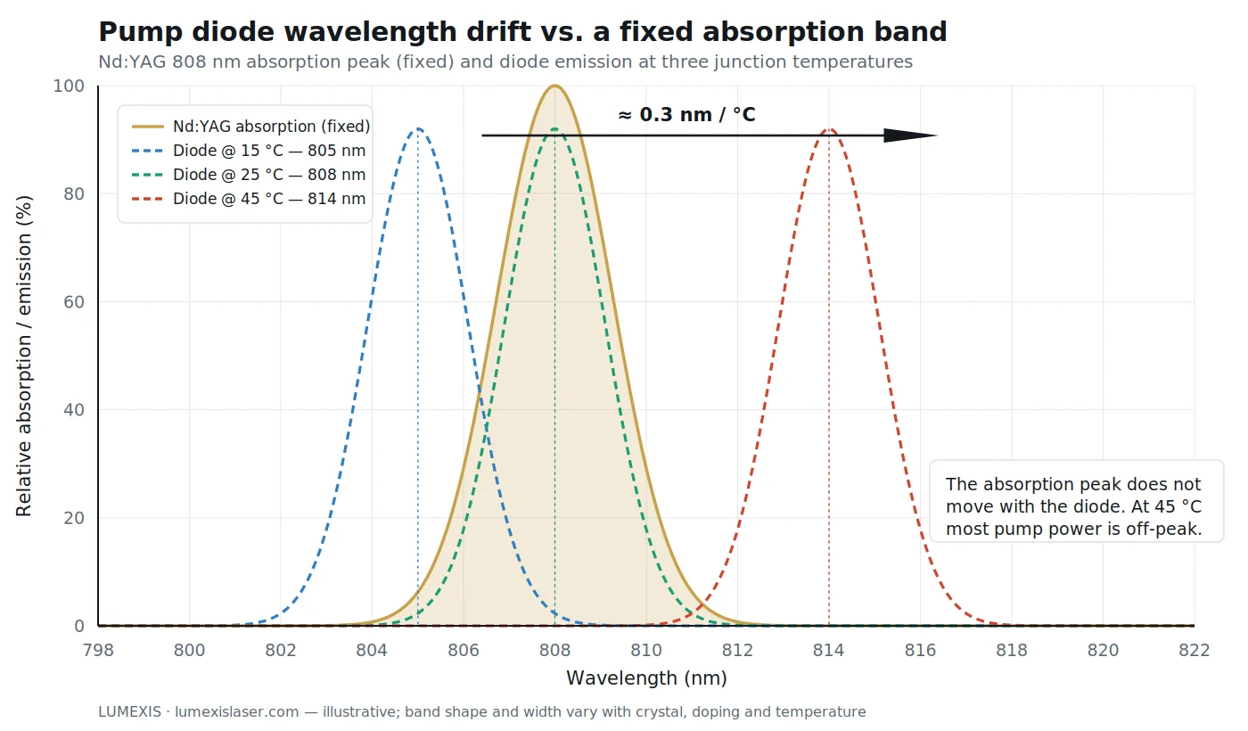
A pump diode’s emission wavelength moves with junction temperature, typically around 0.3 nm per °C. The gain medium’s absorption peak does not move with it.
Run the math on that and the problem is obvious. A diode specified at 808 nm at 25 °C is emitting closer to 811 nm at 35 °C. If your crystal’s absorption band is a few nanometers wide, you have walked partly off the peak, absorbed less pump, and lost output — and the shortfall gets blamed on the crystal or the resonator, because those are easier to inspect.
Three approaches exist, and they suit different products.
Active temperature control with a TEC holds the diode at a fixed junction temperature. It works, and it costs power, volume, and a control loop that can itself fail. On a battery-powered or size-constrained platform this is often the wrong answer.
Wavelength-stabilized diodes using a volume Bragg grating lock emission largely independent of temperature. This costs more per diode and typically some efficiency, but it removes the TEC.
TEC-less design accepts the drift and engineers around it — choosing a broader absorption feature, biasing the nominal wavelength so the drift lands on-peak at the most demanding operating point, or accepting a specified output derating across temperature. Done deliberately, this produces the simplest and most robust system. Done accidentally, it produces a laser that works in the lab and disappoints in the field.
Our team designs for TEC-less operation wherever the application allows it, because for UAV, vehicle-mounted, and handheld platforms the removed complexity is usually worth more than the last few percent of efficiency. That analysis is application-specific, though, and it belongs in the first design review rather than the qualification phase.
Temperature control is only the last link in the chain. The junction temperature that sets your wavelength is the sum of everything between the active region and your cold plate: submount, solder, baseplate, thermal interface material. Aluminium nitride and copper-tungsten submounts are used because they conduct well and, more importantly, because their thermal expansion is close to the semiconductor’s — a mismatch here does not cause a thermal problem, it causes a mechanical one, as every power cycle works the solder joint a little further. Diamond appears where power density leaves no alternative.
Above that stack the choice is conduction cooling to a chassis, which is simple and sealed, or microchannel water cooling, which handles far higher flux but adds plumbing, corrosion and a failure mode that takes the diode with it.
Get this wrong and the failure is not gradual. Catastrophic optical mirror damage is the emitting facet melting under its own optical field, and it is a single-event, unrecoverable failure. Slow facet oxidation in a non-hermetic package is the same story told over years. Both are why derating matters: a diode run at 70% of rated current typically lives several times longer than one run at 100%, and that is usually a cheaper way to buy lifetime than a larger cooler.
The efficiency chain: where 100 electrical watts actually go
Quantum defect is the loss engineers quote, but it is one term in a chain, and the chain is multiplicative. Work an 808 nm-pumped Nd:YAG example end to end with ordinary — not optimistic — numbers:
| Stage | Typical factor | Running total from 100 W electrical |
|---|---|---|
| Diode electrical-to-optical conversion | 55% | 55 W optical |
| Coupling into the delivery fibre | 90% | 49.5 W at the fibre end |
| Delivery and mode matching into the crystal | 92% | 45.5 W incident |
| Absorption in the crystal | 92% | 41.9 W absorbed |
| Quantum defect, 808 → 1064 nm | 75.9% retained | 31.8 W as 1064 nm photons |
| Upper-state losses, resonator losses, output coupling | ~60% | ≈19 W out |
Roughly 19% wall-plug, and about 81 W of heat spread across the diode package, the coupling optics and the crystal. Two things fall out of that table. First, the largest single loss is the diode itself, not the quantum defect — which is why diode efficiency and coupling efficiency deserve the scrutiny normally reserved for the resonator. Second, moving to 888 nm improves exactly one line of this table, from 75.9% to 83.5% retained — worth around 2 W of extra output, but a great deal more in reduced crystal heating and thermal lensing.
Run the table with your own numbers before you commit to an architecture. It is the fastest way to find out whether your thermal budget is realistic, and it usually reorders the priority list.
How to read a pump diode datasheet skeptically
Pump modules are commodity-priced and are not commodities. The differences that matter are mostly not on the front page of the datasheet.
Is the wavelength a specification or a typical value, and at what case temperature? A center wavelength quoted without a reference temperature and a tolerance is not a number you can design to.
What is the coupling efficiency into the delivery fiber, and how was it measured? Fiber-coupled power at the connector is the number that matters to your system. Chip power is not.
Was every unit burn-in screened, or a sample? Diode lasers show early-life failures. Burn-in is the only practical way to find them before they find your customer, and screening every unit costs the supplier real yield — which is why some skip it.
What does the package do about moisture? Hermetic sealing is what keeps facet degradation from accumulating over years in humid or cycled environments. An unhermetic package can look identical on a datasheet and behave very differently at year three.
Is there data across the full operating window? Performance at 25 °C tells you almost nothing about performance at −40 °C or +70 °C. Ask for the temperature-cycled data, not the ambient bench test.
This is the reasoning behind how we build fiber-coupled diode pump sources: incoming inspection, chip test, die bonding and chip-on-submount assembly, automated fiber coupling, hermetic sealing by parallel seam welding, then burn-in and full-window temperature cycling before final test. The vertical integration matters less as a marketing point than as a traceability one — when a unit behaves oddly, we can find out why. You can see the manufacturing and test capability behind that flow, or browse available laser source modules if you are scoping a specific wavelength and power.
Frequently asked questions
What is the difference between pumping and lasing?
Pumping puts energy into the gain medium to create population inversion. Lasing is what happens next: stimulated emission amplifies light within a resonator until it becomes a coherent output beam. Pumping is the input; lasing is the result.
Why are laser diodes used to pump other lasers?
Diode emission can be matched to a narrow absorption band of the gain medium, so nearly all pump energy is absorbed usefully instead of turning into heat. Flashlamps emit broadband light, most of which is wasted. Diodes also last far longer and run at much lower voltage.
What is quantum defect in laser pumping?
It is the energy difference between a pump photon and a laser photon, released as heat in the gain medium. Pumping Nd:YAG at 808 nm to emit at 1064 nm loses roughly a quarter of the pump photon energy this way. It sets the minimum thermal load of the design.
What does end pumping mean?
The pump light enters along the resonator axis, usually through a dichroic mirror, so the pumped volume overlaps the laser mode closely. This gives high efficiency and good beam quality, but concentrates heat and requires a reasonably bright pump source.
Do pump diodes need temperature control?
Not always. Emission wavelength drifts roughly 0.3 nm per °C, so some designs use a TEC or a wavelength-stabilized diode. Others are engineered for TEC-less operation by choosing a tolerant absorption band and biasing the nominal wavelength — simpler and more robust where the application allows.
Why is 976 nm used for fiber laser pumping?
Ytterbium and erbium-ytterbium doped fibers have a strong absorption feature near 976 nm. Combined with cladding pumping, this lets multimode fiber-coupled diodes drive a single-mode output efficiently — the basis of most high-power and 1.5 µm eye-safe fiber laser systems.
What are the main types of laser pumping?
Optical pumping (flashlamps or, far more commonly now, laser diodes), electrical pumping (a gas discharge, or current across a semiconductor junction), and chemical pumping (energy from a reaction). Optical diode pumping subdivides further into end, side, fibre-coupled and cladding-pumped geometries, and that geometry choice usually matters more to a product than the category itself.
What is the difference between CW and QCW pumping?
CW pumping runs the diode continuously at a steady thermal load. QCW pumping runs it in short pulses, typically a few hundred microseconds, around each output pulse. Because the diode only dissipates during a fraction of the cycle, it can be driven well above its CW current rating, giving much higher peak pump power from the same package. QCW is what makes compact, battery-powered pulsed lasers such as rangefinders practical.
What is in-band or resonant pumping?
Pumping directly into the upper laser level instead of into a higher absorption band that must then relax into it. It cuts the quantum defect sharply — 888 nm into Nd:YVO4 instead of 808 nm, or 976 nm into ytterbium for 1030 nm output. The cost is weaker absorption, so the crystal or fibre has to be longer.
How long should a pump pulse be?
On the order of the gain medium’s upper-level fluorescence lifetime — roughly 230 µs for Nd:YAG, under 100 µs for Nd:YVO4, milliseconds for Er:glass. Pumping much longer than that does not store additional energy; it only adds heat.
Specifying the pump before you specify the laser
If you are early in a design, settle the pump questions first: wavelength and its tolerance across your real operating temperature, delivered power at the fiber, geometry, and whether you can live without a TEC. Those four answers constrain the resonator far more than the resonator constrains them.
Send us your gain medium, output requirement, and environmental envelope, and our engineers will work through the pump options with you — including the trade between wavelength stabilization and TEC-less simplicity for your specific platform.
References
- RP Photonics Encyclopedia — Optical Pumping
- Coherent — What is Laser Pumping?
- Laser Focus World — Enhance your Nd-doped DPSS laser with a longer-wavelength pump
- Gentec-EO — What is population inversion in a laser?
- RP Photonics Encyclopedia — Quantum Defect
- RP Photonics Encyclopedia — Upper-state Lifetime
- RP Photonics Encyclopedia — Brightness
- RP Photonics Encyclopedia — Double-clad Fibers
- RP Photonics Encyclopedia — Wavelength-stabilized Laser Diodes