








When a laser source must deliver light through a compact instrument, a remote optical head, or a tightly controlled beam path, free-space delivery can become the fragile part of the design. Alignment takes space. The source and its cooling hardware compete with the work head. Cable routing, service access, and repeatability all become system questions.
A fiber-coupled laser moves that interface into the source design. But “fiber coupled” is not a complete specification. The value of the finished module depends on the emitter, coupling optics, fiber core, numerical aperture, termination, thermal path, and the conditions under which the delivered output is verified.
Table of Contents
What is a fiber coupled laser? It is a laser source whose output is launched through coupling optics into a passive optical fiber for controlled delivery. It is not automatically a fiber laser: the source, fiber, and host optics still need to be matched so the delivered beam has the power, geometry, stability, and serviceability your system requires.
For an OEM team asking what is a fiber coupled laser for a specific instrument, the practical answer begins at the required fiber output—not with a generic catalog label.
What is a fiber coupled laser—and what is it not?
A fiber-coupled laser is defined by its delivery path. A diode emitter, for example, produces light at the source. Micro-optics collect and reshape that output, then launch it into the core of an optical fiber. The fiber carries the light to a connector, a splice, or an integrated optical assembly where the host system uses it.
That is different from a fiber laser. In a fiber laser, a doped fiber is part of the gain medium that creates or amplifies the laser light. A fiber-coupled diode laser can be used to pump a fiber laser or a solid-state laser, but the terms describe different roles in the optical system.
For an OEM, the useful question is not simply whether the output is fiber coupled. It is whether the source-to-fiber interface makes the desired delivery condition repeatable inside the finished instrument. The available laser-source and module range is a useful starting point, but the application requirement should determine the configuration.
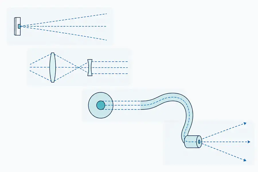
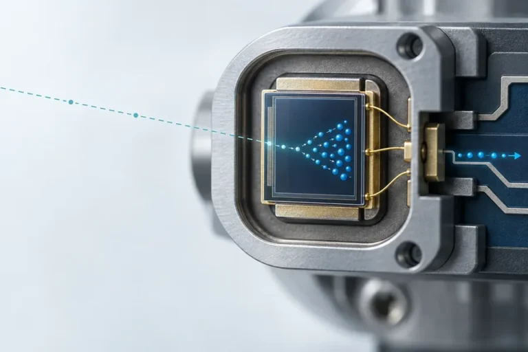
Typical delivery-chain concept: source emission is collected and matched into a passive fiber. Dashed paths are shown for visualization.
How does fiber coupling work?
Laser-diode output is not naturally shaped for every fiber. Edge-emitting diodes can have asymmetric divergence, and different emitter families present different beam geometry. Coupling optics collect that light, manage its spatial and angular distribution, and focus it toward the fiber input. The coupling task is successful only when the beam fits both the effective input area and the acceptance angle of the chosen fiber.
Numerical aperture, usually written as NA, describes the angular acceptance of the fiber. Core diameter describes the physical region available for guided light. Both matter, but neither tells the whole story by itself. Alignment, source beam quality, lens design, wavelength, and the distribution of light across guided modes also affect what reaches the output.
This is why a data sheet needs an operating condition, not only a headline power number. A change in drive condition, temperature, optics, fiber type, or termination can alter the delivered result. RP Photonics notes that diode output can be elliptical and astigmatic, so the coupling optics must address the actual emitter behavior rather than assume an ideal circular beam.
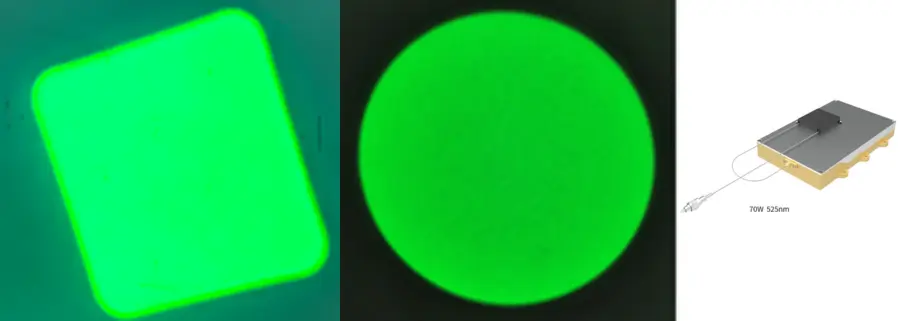
The five specifications that determine whether the delivered beam will fit
The most efficient module is not automatically the best source for the host system. Start with the condition required at the fiber output, then work back toward the emitter and package.
1. Wavelength and operating mode
The wavelength must fit the absorption, sensing, illumination, or pumping task. CW, QCW, and pulsed operation also need to be stated because duty cycle and thermal loading change the electrical and optical operating point. For a pumping application, the source wavelength should be evaluated with the gain medium, absorption bandwidth, thermal behavior, and required output geometry. Our laser-pumping solution provides the relevant system context.
2. Fiber core diameter and numerical aperture
A larger core and higher NA can make it easier to accept light from a high-divergence or multimode source. The trade-off is that the delivered beam may be harder to focus into a small, bright spot later. A smaller core can support a tighter delivery condition, but it places stricter demands on the emitter, coupling optics, alignment, and mechanical stability.
Do not select a core size from a catalog shortcut. Start with the spot size, working distance, downstream optics, and power-density requirement at the application. Then confirm whether the proposed core/NA combination preserves a useful margin for manufacturing and integration tolerances.
3. Single-mode, multimode, or polarization-maintaining fiber
Single-mode fiber is used when beam quality, spatial mode control, or a compact focused spot is central to the application. Multimode fiber can accept more modes and is often appropriate where higher delivered power, a larger spot, or more relaxed beam quality is acceptable. Polarization-maintaining fiber is a separate requirement when the downstream optical function depends on a controlled polarization state.
These are not interchangeable labels. The correct choice depends on the optical task, not on a general preference for smaller or larger fiber. For a concrete product-family example, review the fiber/interface options alongside 976 nm fiber-coupled laser options rather than assuming one configuration fits every pump design.
4. Termination and serviceability
Pigtailed modules have a fiber permanently attached to the package. That can support a stable source-side coupling arrangement, but it makes fiber handling and replacement part of the system plan. Receptacle-style modules accept a detachable fiber interface. They can simplify service and reconfiguration, while adding a mating interface that must be controlled for cleanliness, alignment, and return-light behavior.
Specify the termination with the host instrument, not separately. Connector choice, splice method, bend radius, cleaning process, and downstream cable routing all affect the real delivery path.
5. Beam quality, brightness, and the output condition
Fiber delivery can make a source easier to route and integrate, but it does not create brightness. In multimode systems, core diameter, NA, launch conditions, and modal distribution influence the output beam quality. A module may deliver the required optical power while still being a poor fit for a small focused spot or a high-resolution illumination path.
Request the output condition that matters to the host system: fiber type, core, NA, wavelength, operating mode, output power, beam characterization where relevant, and the test method. That discipline prevents a source-level claim from being mistaken for an application-level result.
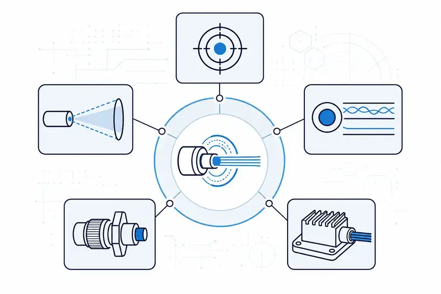
Select the fiber interface from the required output condition, not from one catalog field alone.
What fiber coupling improves—and what it can cost
Fiber coupling can put the source and its thermal hardware where the system can support them, while the delivery fiber routes light to a smaller or more constrained optical head. It can also create a more controlled source interface for instrument builders who need repeatable assembly and a defined delivery path. In many pumping systems, it separates the pump package from the gain medium and simplifies how the optical head is arranged; our guide to how solid-state laser pumping works explains why that system separation matters.
The trade-offs deserve equal attention. Every launch introduces coupling loss. A fiber interface can reduce usable brightness or alter the output geometry. Bending, connector contamination, optical feedback, and thermal expansion can affect the behavior of the assembly. Returned light from downstream optics or the work surface must be considered in the complete optical path rather than after the module is selected.
At higher optical loads, the thermal path, fiber-end condition, connector specification, and protection strategy become engineering inputs. A responsible product description states what was tested, under which configuration, and where the host system introduces a new boundary.
Match the configuration to the engineering task
For industrial laser pumping, the key question is usually how the pump source, fiber delivery, absorption condition, and thermal architecture work together. A source that is easy to couple into a large-core delivery fiber may be appropriate when the downstream gain medium and optics can accept that geometry. A source intended for a tighter optical spot needs a different balance of emitter, core, NA, and beam quality.
For machine vision and optical inspection, uniformity, working distance, target geometry, and the receiving optics can matter as much as total delivered output. The right configuration begins with the illumination task and host optics; see the application framing in our machine-vision illumination page.
For scientific instruments, wavelength stability, fiber type, connector convention, packaging, and the method used to verify output can all be decisive. The common thread is simple: define the output condition at the instrument interface first, then select the source architecture that can produce it repeatably.
What to put in a fiber-coupled-laser RFQ
An RFQ should let the supplier evaluate the delivery path as a system. Include:
- wavelength and tolerance needed by the application;
- CW, QCW, or pulsed operating condition, including duty cycle where relevant;
- required output at the stated fiber interface and test condition;
- fiber core, NA, fiber type, length, and termination;
- host optics, desired spot or illumination geometry, and working distance;
- thermal interface, available cooling, and operating environment;
- return-light, bend, cleanliness, and service-access conditions;
- electrical interface, control requirement, annual volume, and change-control expectation.
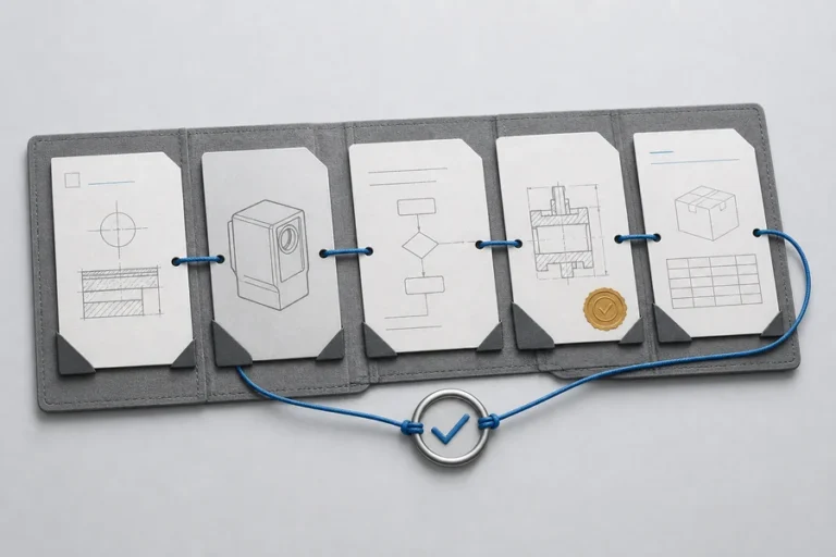
This is also the point to ask how the proposed configuration is aligned, screened, and re-verified in production. A purchase decision based only on a nominal wavelength and output label leaves too much integration risk unresolved.
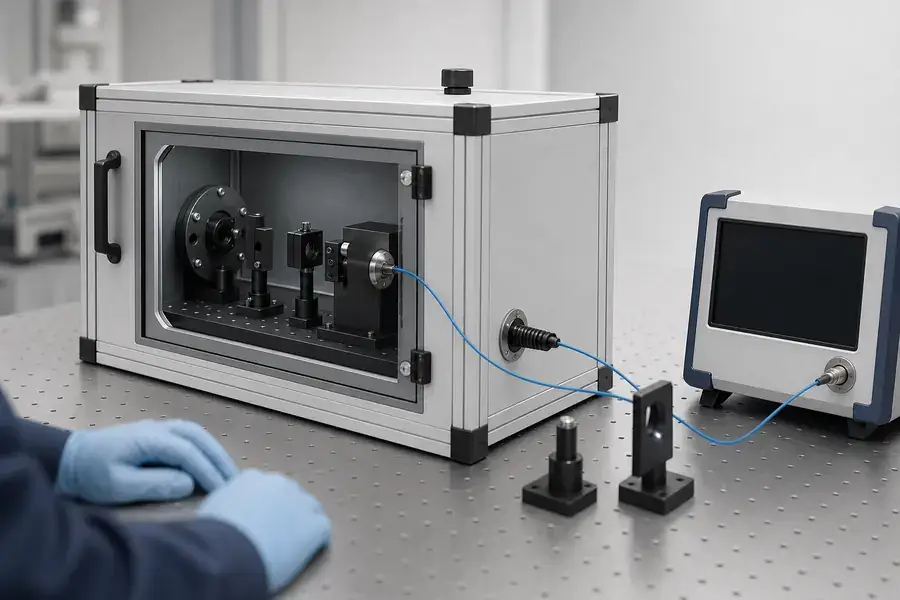
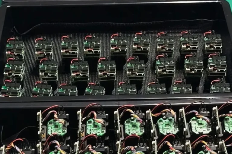
Conceptual engineering context for controlled fiber alignment and output verification; this is not a customer or production record.
How Lumexis supports a defined delivery path
At Lumexis, we approach fiber-coupled laser selection as an interface problem across optics, mechanics, electronics, thermal design, and production verification. Our team works across optical and optomechanical design, semiconductor laser packaging, fiber coupling, electronics and firmware, and test-method development. That helps OEM teams connect a desired fiber output to the rest of the instrument rather than treating the laser module as an isolated part.
Our documented production flow includes incoming inspection, chip test, die bonding, mounting, fiber coupling and alignment, sealing, burn-in screening, and final performance testing. Those controls support a defined build; they do not replace application-specific validation. You can review the relevant laser-source technology capabilities and discuss a non-standard interface through custom OEM laser development. Standard products can ship within three days when the required configuration is available; custom lead time should be confirmed against the actual requirement.
FAQ
Is a fiber-coupled laser the same as a fiber laser?
No. A fiber-coupled laser describes how light from a source is delivered through a passive optical fiber. A fiber laser uses doped fiber as a gain medium. A fiber-coupled diode can pump a fiber laser, but the two terms should not be used as substitutes.
Does a larger fiber core always make a laser easier to use?
Not always. A larger core can accept light more easily from some source architectures, but it can also reduce the ability to form a small, bright spot at the output. Select core size with NA, beam-quality needs, downstream optics, and the actual application geometry.
What is numerical aperture in a fiber-coupled laser?
Numerical aperture describes the angular range of light the fiber can accept and guide. It must be considered with core size, source divergence, coupling optics, and launch conditions. It is a coupling constraint, not a stand-alone indicator of delivered application performance.
Should I choose a pigtailed or receptacle-style module?
Choose from the system’s service, alignment, and interface needs. A pigtailed source can provide a fixed source-side fiber arrangement. A receptacle can make a patch cable easier to replace, but the mating interface adds cleanliness, alignment, and return-light considerations.
What should be checked before connecting a high-power delivery fiber?
Confirm the connector and fiber are compatible with the source and intended load, inspect and clean the mating faces using the approved procedure, control bend radius, and evaluate downstream reflections. The final system should have a documented optical, mechanical, and thermal boundary rather than relying on a connector name alone.
If you are defining a fiber-coupled source for an OEM instrument, contact our engineering team with the wavelength, operating mode, required output, core/NA, connector, host optics, thermal environment, and expected volume. We can help assess a standard configuration or review a custom delivery path.