
Medición aerotransportada civil
Rango láser en UAV: Comience con la tarea de medición
Lumexis desarrolla un compacto de 1535 nm módulos de telémetro láser para teledetección aerotransportada civil, medición de altura del terreno, medición de distancia de infraestructura, medición de puntos asistida por cámara y perfilado de superficie científica.
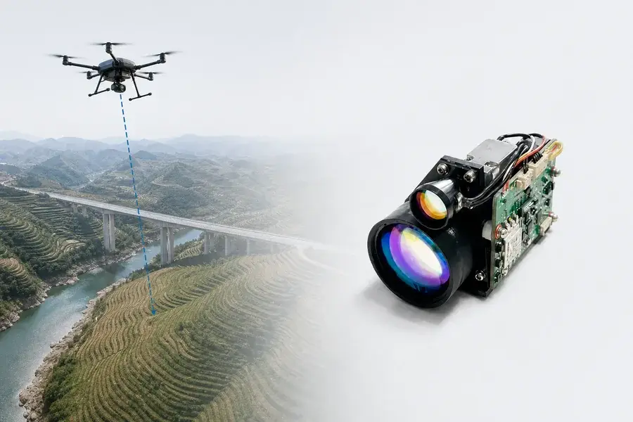
Lumexis desarrolla y fabrica módulos compactos de telémetro láser de 1535 nm para sistemas de medición aerotransportados civiles. Nuestros módulos brindan a los ingenieros de carga útil un canal de distancia directo por tiempo de vuelo que puede respaldar la medición de altura del terreno, la medición de distancia de infraestructura, la medición de puntos asistida por cámara y el perfilado de superficie científica.
Comience con la tarea de medición, no con el número de rango más grande.
Para una coincidencia rápida del módulo, defina:
- si la salida requerida es rango oblicuo, altura vertical o un punto de superficie georreferenciado;
- la distancia normal y máxima entre el sensor y la superficie;
- el material de la superficie, la pendiente, la vegetación, la humedad y el ángulo de incidencia esperado;
- la masa disponible, el envolvente, la potencia promedio y el presupuesto de potencia máxima;
- la tasa de medición requerida, la precisión de la marca de tiempo y el comportamiento de lectura no válida;
- los sensores del host disponibles para posición, actitud, ángulo de apuntado y alineación de la cámara.
Ruta rápida: Envíe a Lumexis su envolvente de altura, tipo de superficie, presupuesto de carga útil e interfaz del host.
Comience con la tarea de medición aerotransportada
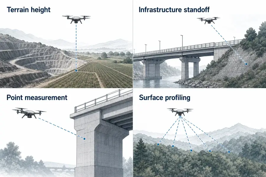
Adecuación a la aplicación
Adapte la fuente óptica a la tarea de medición real
Cuatro aplicaciones civiles de rango láser aerotransportado: altura del terreno, distancia de infraestructura, medición de puntos y perfilado de superficie.
| Aplicación | Salida que el canal de rango puede respaldar | Lo que el host debe agregar | Inicie la solicitud de cotización con |
|---|---|---|---|
| Medición de altura del terreno | Distancia al terreno o estructura iluminada | Compensación de actitud para altura vertical; lógica de terreno si se mide sobre la superficie directamente debajo de la plataforma | envolvente de altura, tipo de superficie, inclinación de la plataforma, tasa, masa |
| Inspección de infraestructura civil | Distancia a un elemento de puente, pendiente, torre, estructura junto a la vía o activo grande | Alineación de cámara o ángulo de apuntado; selección de objetivo; posición de la plataforma cuando se requieren coordenadas | tamaño del objetivo, material, ángulo, distancia máxima, vibración |
| Medición de puntos asistida por cámara | Rango a lo largo de la línea de visión de la cámara o del cardán | Parámetros intrínsecos de la cámara, alineación de la cámara con el telémetro, posición y actitud de la plataforma | campo de visión, tolerancia de alineación, marca de tiempo, interfaz |
| Teledetección científica | Muestras de rango repetidas a lo largo de una trayectoria conocida | GNSS/IMU, sincronización de tiempo, geometría de montaje calibrada, registro de datos | trayectoria, espaciado de muestras, respuesta de superficie, marco de coordenadas |
| Perfilado de superficie | Una serie de retornos de rango a lo largo de direcciones de mirada comandadas | Un mecanismo de escaneo o apuntado y un procesamiento que asigna un ángulo y una pose a cada muestra | geometría de escaneo, codificador angular, tasa, superposición, calibración |
Un telémetro de punto único es una buena opción cuando
- el sistema necesita una distancia absoluta a lo largo de una dirección de mirada conocida;
- la carga útil ya contiene una cámara, cardán, receptor GNSS, IMU o codificador angular;
- la baja masa y la baja potencia promedio importan más que la salida densa de nube de puntos;
- las tasas de medición de 1–10 Hz se adaptan al flujo de trabajo de actualización y registro requerido;
- el objetivo es un parche de terreno o una estructura civil lo suficientemente grande como para interceptar la huella útil del haz.
Elija un LiDAR de escaneo en su lugar cuando
- el entregable principal es una nube de puntos 2D o 3D densa de cada pasada;
- la alta densidad de pulsos y la amplia cobertura angular son requisitos fundamentales;
- la estructura del dosel o múltiples capas verticales deben resolverse sistemáticamente;
- se requiere una precisión de mapeo de clase centimétrica desde una carga útil de topografía totalmente integrada.
Un módulo de telémetro láser, un altímetro láser y un LiDAR de escaneo miden todos el Tiempo de Vuelo óptico, pero no son productos intercambiables. La elección correcta depende de los datos de salida, la geometría de muestreo y la cadena de calibración, no solo de la longitud de onda.
Haga coincidir el módulo Lumexis con los límites de alcance y carga útil
Para cargas útiles de UAV civiles, la masa, el volumen, la apertura de recepción, la potencia, el alcance mínimo y la interfaz de comunicación a menudo eliminan opciones no adecuadas antes de que lo haga el alcance máximo.
Los valores de alcance a continuación son valores de objetivo de referencia, no alturas de vuelo garantizadas. Están vinculados a un objetivo de 2,3 × 2,3 m con reflectividad de al menos 0,3 bajo la condición de visibilidad indicada en la especificación de la fuente. Una huella de terreno amplia, un techo oscuro, una superficie mojada, un dosel, una pendiente oblicua, una ventana contaminada o una línea de visión inestable pueden producir un alcance útil diferente.
| Modelo Lumexis | Alcance de objetivo de referencia | Apertura de recepción | Divergencia del haz | Alcance mínimo | Precisión | Tasa | Dimensiones máximas | Masa | Potencia promedio típica a 1 Hz |
|---|---|---|---|---|---|---|---|---|---|
| 1535-LXCJ0300 | ≥3,2 km* | Φ16 mm | ≤0,6 mrad | ≤15 m | ≤±1 m | 1–10 Hz | 48 × 21 × 31 mm | 33 ± 1 g | ≤0,8 W |
| 1535-LXCJ0500 | ≥5 km** | Φ16 mm | Confirmar por configuración | ≤15 m | ≤±1 m | 1–10 Hz | 50 × 23 × 33.5 mm | ≤40 g | ≤1 W |
| 1535-LXCJ0600 | ≥6 km** | Φ21 mm | ≤0,3 mrad | ≤20 m | ≤±1 m | 1–10 Hz | 65 × 40 × 28 mm | ≤55 g | ≤1 W |
| 1535-LXCJ0700 | ≥7 km** | Φ25 mm | ≤0,3 mrad | ≤30 m | ≤±1 m | 1–10 Hz | 65 × 46 × 32 mm | ≤72 g | ≤1,3 W |
| 1535-LXCJ0800 | ≥8 km** | Φ25 mm | ≤0,3 mrad | ≤30 m | ≤±1 m | 1–10 Hz | 65 × 46 × 32 mm | ≤72 g | ≤1,3 W |
* Visibilidad de referencia de la fuente ≥12 km.
** Visibilidad de referencia de la fuente ≥20 km.
Las plataformas Lumexis de mayor alcance están disponibles hasta la clase de objetivo de referencia de 15 km. Utilizan aperturas de recepción y paquetes más grandes, por lo que un ingeniero de carga útil debe seleccionarlas solo cuando el requisito real de alcance oblicuo y margen de retorno justifique el tamaño y la masa adicionales.
Lógica de selección práctica
Elija el 1535-LXCJ0300 primero cuando el entorno de trabajo verificado se ajuste a sus condiciones de objetivo y visibilidad y la masa más baja listada sea la prioridad.
Pase al 1535-LXCJ0500 o 0600 cuando el presupuesto de retorno del objetivo necesite más margen de alcance, mientras la carga útil pueda aceptar el volumen o la apertura más grandes.
Considere la clase 0700 u 0800 para un distanciamiento oblicuo más largo hacia grandes estructuras civiles o medición de superficie a mayor altitud, después de verificar masa, estabilidad de apuntado, apertura de ventana y retorno real de la superficie.
No agregue margen de alcance a ciegas. Un módulo más grande puede consumir capacidad de carga útil sin corregir un error causado por actitud, desajuste de marca de tiempo, desalineación del eje, ángulo del objetivo o una superficie no adecuada.
Lo que mide el módulo: alcance oblicuo
Un telémetro láser pulsado emite un pulso óptico corto y mide el tiempo de ida y vuelta hasta el retorno de la superficie detectada:
R = cΔt / 2
donde:
- (R) es el alcance oblicuo de un solo sentido;
- (c) es la velocidad de la luz en el medio de propagación;
- (Δ t) es el intervalo de ida y vuelta medido;
- el factor de dos tiene en cuenta las trayectorias de salida y retorno.
Este resultado es una distancia a lo largo de la dirección de medición. No es automáticamente altura sobre el suelo, altura sobre el nivel del mar ni una coordenada de mapa.
El alcance oblicuo no siempre es altura vertical
Visual de ingeniería
Vea cómo la fuente se ajusta al instrumento completo
Diagrama de geometría que muestra el alcance oblicuo, el componente vertical, la actitud de la plataforma y la pendiente del terreno.
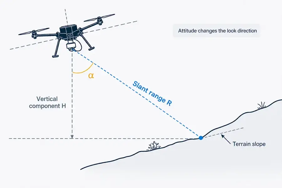
Si (α) es el ángulo entre la dirección de observación medida y la vertical local, la separación vertical entre el sensor y el punto del terreno iluminado es:
H = R cos α
Esta relación simple es útil, pero no resuelve el problema completo de la medición aerotransportada.
- Si el módulo apunta exactamente al nadir local, (α) se aproxima a cero y (H) se aproxima a (R).
- Si la plataforma se inclina o cabecea mientras el módulo está fijado al fuselaje, la dirección de observación cambia con la plataforma.
- Si un cardán apunta el módulo fuera del nadir, el ángulo del cardán pertenece a la transformación.
- Si el haz incide en una pendiente alejada del punto directamente debajo de la plataforma, (H) es la separación vertical hasta el punto iluminado, no necesariamente la altura de la plataforma sobre el terreno directamente debajo de ella.
- Si la salida requerida es la elevación, el sistema también debe conocer la posición del sensor y el datum de referencia.
En ángulos pequeños, la diferencia de alcance a altura puede parecer moderada, pero la incertidumbre angular crea un desplazamiento horizontal de la huella y puede convertirse en un error vertical importante sobre terreno inclinado. El presupuesto de errores debe incluir la calidad de la actitud de la IMU, el ángulo de montaje del telémetro a la IMU, el ángulo del cardán o codificador, la flexión estructural y la alineación temporal.
De un valor de alcance a un punto de superficie
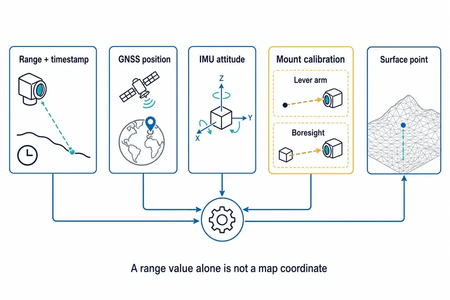
Principio de medición
Conectar la medición óptica con la geometría del sistema
Diagrama de flujo de señal que muestra el alcance y la marca de tiempo, la posición GNSS, la actitud de la IMU, el brazo de palanca y el boresight que contribuyen a un punto de superficie.
En un marco de mapeo simplificado:
psuperficie = psensor + Ruobservación
donde:
- (psensor) es la posición del centro óptico del sensor en el marco de mapeo;
- (R) es el alcance oblicuo medido;
- (uobservación) es un vector unitario que describe la dirección de medición en el mismo marco;
- (pobjetivo) es el punto de superficie iluminado.
El término difícil suele ser (uobservación). Debe derivarse de:
- el eje óptico del telémetro;
- su rotación de boresight fija relativa al marco de la IMU o de la carga útil;
- cualquier ángulo de cardán o escáner;
- el balanceo, cabeceo y rumbo de la plataforma en el momento de la medición;
- la convención de coordenadas local o global elegida.
La posición del sensor también necesita más que una coordenada GNSS. El desplazamiento desde el punto de referencia GNSS/IMU hasta el centro óptico del telémetro—el brazo de palanca—debe medirse en un marco de cuerpo definido y transformarse con la actitud. Los flujos de trabajo de datos aerotransportados de la NOAA y los estudios publicados de UAS-LiDAR identifican el procesamiento GNSS/IMU, los desplazamientos del brazo de palanca, la calibración del boresight, las líneas superpuestas y la sincronización temporal como partes centrales de la georreferenciación.12
La sincronización temporal es un parámetro geométrico
En una plataforma en movimiento, una muestra de alcance con la marca de tiempo incorrecta recibe la posición y orientación incorrectas. Una especificación de interfaz útil debería cubrir por lo tanto:
- cuándo se crea la marca de tiempo del alcance;
- si representa disparo, emisión, detección o transmisión de paquete;
- comportamiento del reloj del host y del módulo;
- latencia y variación de comando a medición;
- retardo de transporte serie;
- estrategia de sincronización de tiempo GNSS o pulso por segundo;
- cómo se marcan las mediciones inválidas, obsoletas o perdidas.
Para la medición puntual, registre el alcance bruto, el estado de validez, el tiempo del módulo, el tiempo de recepción del host, la posición de la plataforma, la actitud de la plataforma, el ángulo del cardán y la revisión de configuración. Conserve suficiente información para recalcular coordenadas después de que mejore la calibración.
El retorno de superficie decide si la distancia es útil
Respuesta de medición
Interpretar la respuesta óptica en el contexto de la aplicación
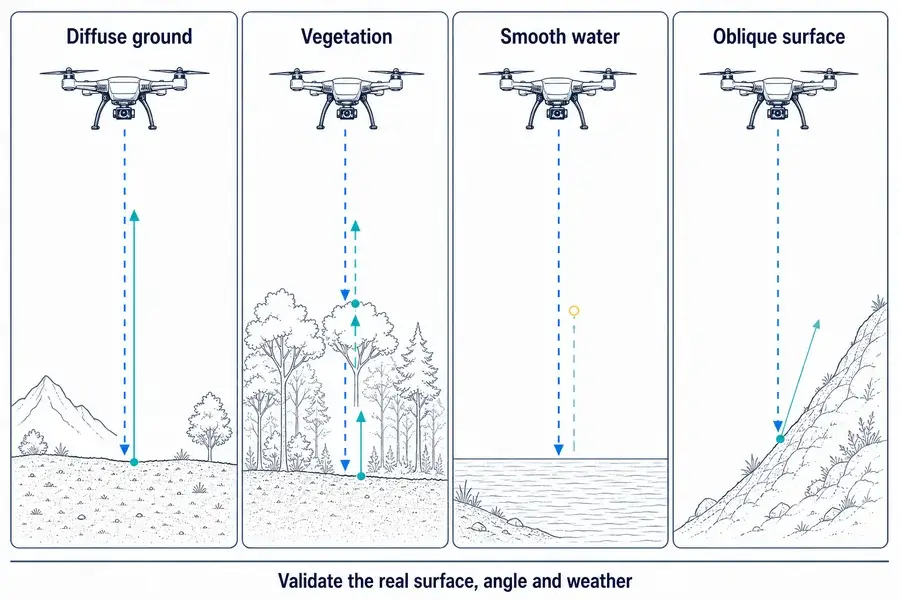
Comparación de condiciones de retorno de suelo difuso, vegetación, agua lisa y superficie oblicua para telemetría aerotransportada.
Suelo difuso y estructuras civiles
Suelo seco, roca, hormigón, superficies pintadas y techados pueden devolver diferentes cantidades de energía a 1535 nm. La textura, la humedad, la contaminación y el ángulo de incidencia importan. No aplique un juicio de color visible como “las superficies claras siempre alcanzan mayor distancia” sin validación específica de longitud de onda.
Vegetación
Un solo pulso puede interactuar con un dosel, ramas, sotobosque y suelo. Un módulo con lógica de múltiples objetivos o de primer/último retorno puede ofrecer opciones útiles, pero un canal de punto único de 1–10 Hz no sustituye a un instrumento de resolución de forma de onda o de escaneo de alta densidad cuando la estructura del dosel es el requisito del producto. La investigación aérea del USGS demuestra por qué los métodos de primera superficie, última superficie y forma de onda completa responden a diferentes preguntas sobre vegetación.3
Agua lisa y superficies húmedas
La medición de distancia por infrarrojo cercano e infrarrojo de onda corta no debe presentarse como medición batimétrica. La absorción del agua, el ángulo de la superficie, el estado de las olas, la turbidez y la reflexión especular pueden producir retornos débiles, intermitentes o ausentes. El LiDAR batimétrico verde utiliza una estrategia de longitud de onda diferente para la penetración en el agua.4
Pendientes oblicuas y caras de estructuras
Una superficie oblicua puede redirigir gran parte de la energía reflejada lejos del receptor. La huella proyectada también se estira sobre la superficie, y el alcance puede variar a lo largo de esa huella. Valide el ángulo de incidencia máximo esperado en la trayectoria real, no solo un panel perpendicular en el banco de pruebas.
Atmósfera y ventana externa
Niebla, lluvia, polvo, aerosoles, condensación y contaminación reducen el retorno útil o crean retrodispersión cercana no deseada. La pérdida ocurre tanto en la trayectoria de salida como en la de retorno. Pruebe el payload completo con su ventana externa final; un resultado de banco con módulo desnudo no incluye transmisión de ventana, reflexión interna, contaminación ni alineación del recinto.
La divergencia del haz determina la huella en el suelo
Para una estimación de campo lejano usando divergencia de ángulo completo:
d ≈ Rθ
donde (d) es el diámetro aproximado del punto, (R) es el alcance oblicuo y (θ) es la divergencia de ángulo completo en radianes.
Ejemplos:
- a 500 m, 0.6 mrad corresponde a un punto aproximado de 0.30 m;
- a 1,000 m, 0.6 mrad corresponde a un punto aproximado de 0.60 m;
- a 1,000 m, 0.3 mrad corresponde a un punto aproximado de 0.30 m.
Estas son estimaciones geométricas, no valores de aceptación. El diámetro inicial del haz, el perfil del haz, el enfoque, la aberración óptica, la turbulencia, la vibración y la deriva del haz se omiten.
Para la medición de altura del terreno, una huella más grande puede promediar o mezclar retornos de vegetación, rocas, bordes de techos o suelo inclinado. Para la medición de puntos asistida por cámara, un haz más estrecho puede mejorar el llenado del objetivo, pero también exige una alineación cámara-láser más estricta y un apuntamiento más estable.
En un ángulo de incidencia oblicuo (β), la huella se estira a lo largo de la superficie. En una aproximación geométrica ideal, la dimensión larga aumenta aproximadamente como (1/cosβ). El comportamiento real del retorno también depende de la dispersión de la superficie y la geometría del receptor, así que use esto solo como una guía de diseño.
Por qué 1535 nm es útil—y lo que no garantiza
Un telémetro de 1535 nm comúnmente combina una fuente pulsada de vidrio de erbio con un receptor diseñado para la banda de 1.5 μm. Esta arquitectura puede soportar medición compacta de larga distancia y ofrece un régimen diferente de interacción ocular en comparación con longitudes de onda más cortas del infrarrojo cercano.
Sin embargo:
- la longitud de onda no establece la clase láser del payload terminado;
- la seguridad láser depende de la emisión accesible, propiedades del pulso, repetición, apertura, divergencia, geometría de exposición, carcasa protectora y el método de prueba aplicable;
- una ventana óptica del host puede cambiar el haz accesible;
- una declaración del módulo no debe transferirse automáticamente al producto integrado.
Lumexis debe publicar una declaración formal de clase láser solo cuando la configuración exacta de producción tenga documentación de cumplimiento de respaldo.
Lista de verificación de integración para un payload aéreo civil
Montaje mecánico y alineación de puntería
- Defina los datums del centro óptico y del eje óptico del módulo.
- Monte en una estructura de payload rígida y repetible sin distorsionar la óptica.
- Mida el brazo de palanca desde el punto de referencia de navegación hasta el centro óptico.
- Calibre la rotación de puntería entre el telémetro y el marco de la IMU, cámara o cardán.
- Verifique la alineación antes y después de la exposición a vibración y temperatura.
- Enrute los cables para que no apliquen torque cambiante al módulo o al montaje.
Vibración y movimiento de la plataforma
La trayectoria de medición debe permanecer en la superficie prevista durante la emisión y recepción. Revise:
- vibración relacionada con el rotor y resonancias estructurales;
- ancho de banda de estabilización del cardán;
- sincronización de la cámara de obturador rodante si el alcance se combina con una imagen;
- interpolación de actitud en la marca de tiempo del alcance;
- desenfoque de movimiento y desplazamiento de características en la cámara;
- flexión estructural entre el sensor de navegación y el telémetro.
Una clasificación de vibración en una especificación de componente no prueba la precisión de coordenadas después de la integración. El payload debe verificar tanto la supervivencia funcional como la alineación retenida.
Potencia
- Dimensiona el riel para la potencia máxima, no solo el valor promedio.
- Verifique el voltaje en el módulo durante la emisión, incluyendo la caída de cable y conector.
- Caracterice los estados de arranque, habilitación, espera y medición continua.
- Verifique si el ruido de conmutación afecta a la IMU, receptor GNSS, cámara o radio.
- Registre el voltaje y la corriente de suministro durante las pruebas en tierra y en vuelo.
Comunicación
Las plataformas Lumexis admiten RS422 o TTL según la configuración.
- RS422 es útil cuando la longitud del cable y el ruido eléctrico justifican la señalización diferencial.
- TTL requiere niveles lógicos confirmados, tierra común, longitud del cable y compatibilidad con el host.
- Confirme la revisión del protocolo controlado, la velocidad de baudios, el formato de comandos, el tiempo de espera, el comportamiento de habilitación y los códigos de error.
- Defina qué hace el host después de un rango no válido, tiempo de espera, retorno fuera de rango o pérdida de comunicación.
Ventana óptica y deflector
La ventana del host es parte del sistema óptico.
- Utilice material y recubrimiento con transmisión verificada alrededor de 1535 nm.
- Proporcione aperturas claras separadas para las rutas de transmisión y recepción cuando el módulo seleccionado lo requiera.
- Mantenga la ventana lo suficientemente cerca para evitar el recorte, respetando la tolerancia mecánica.
- Incline y coloque el deflector en la ventana solo después de evaluar los retornos fantasma y el desplazamiento del eje.
- Controle la condensación, el polvo, la película de agua, los rayones, el desbordamiento del adhesivo y el daño del recubrimiento.
- Vuelva a verificar el rango máximo y mínimo con la ventana y el gabinete finales.
Entorno térmico
Los gabinetes aerotransportados experimentan carga solar, flujo de aire, calor interno, cambios rápidos de altitud y enfriamiento prolongado. Verifique:
- la temperatura de la carcasa del módulo, no solo el aire ambiente;
- la deriva de alineación entre el telémetro, la IMU y la cámara;
- el tiempo de arranque después del enfriamiento prolongado;
- el comportamiento del suministro y la validez de la medición en toda la temperatura;
- el riesgo de condensación durante las transiciones.
Plan de validación en tierra y en vuelo
Integración en banco
- verifique la alimentación, la habilitación, los comandos, el formato de respuesta y el manejo de fallas;
- confirme el comportamiento de la marca de tiempo y la latencia de medición;
- establezca los puntos de referencia del módulo a la carga útil;
- pruebe objetivos difusos representativos más allá del rango mínimo especificado;
- utilice procedimientos controlados para superficies cercanas o altamente reflectantes.
Prueba de campo en exteriores
- instale la ventana final, el deflector, el soporte, el cable y el sistema de alimentación;
- mida objetivos conocidos con diferente material, tamaño, ángulo y distancia;
- pruebe la luz de fondo y las condiciones de visibilidad esperadas;
- compare el comportamiento de primer, último y múltiples objetivos donde esté disponible;
- registre los retornos no válidos y faltantes en lugar de filtrarlos silenciosamente.
Apuntamiento estático y calibración
- inspeccione superficies o objetivos de referencia;
- mida los brazos de palanca en el marco del cuerpo elegido;
- determine la línea de visión entre cámara/telémetro y telémetro/IMU;
- verifique la estabilidad del eje óptico después de la manipulación y los ciclos térmicos;
- fije las definiciones de coordenadas y las convenciones de signos.
Prueba de ingeniería aerotransportada de bajo riesgo
- comience sobre un área de prueba civil abierta y controlada con superficies simples;
- registre el rango bruto, la marca de tiempo, GNSS, actitud, ángulo del cardán, alimentación y validez;
- compare pasadas en direcciones opuestas y cruces sobre superficies comunes;
- examine las pérdidas de rango sobre vegetación, agua, bordes y pendientes;
- verifique si la latencia de datos o la interpolación de actitud crean desplazamientos espaciales.
Prueba de aceptación
Defina criterios de aprobación/rechazo para:
- tasa de mediciones válidas por superficie y distancia;
- sesgo de rango y repetibilidad;
- error de altura vertical o de coordenadas de punto después de la transformación completa;
- estabilidad del eje de puntería antes y después de la exposición ambiental;
- comportamiento de lectura no válida;
- margen de potencia, térmico y de comunicación.
La métrica de aceptación debe coincidir con la salida prometida al cliente. Una especificación de alcance de módulo de ±1 m y una precisión vertical o de coordenadas del sistema final son cantidades diferentes.
Qué enviar a Lumexis para una recomendación de módulo
Copie esta lista de verificación en su consulta:
- aplicación: altura del terreno, distancia de estructuras civiles, medición puntual o perfilado de superficies;
- salida requerida: alcance oblicuo, altura vertical, distancia libre relativa o coordenada de superficie;
- distancia normal y máxima entre el sensor y la superficie;
- distancia mínima durante el despegue, manejo o inspección cercana;
- tipos de superficie, estimación de reflectividad, pendiente, vegetación, humedad y ángulo esperado;
- tipo de plataforma y balanceo, cabeceo, velocidad angular máximos y entorno de vibración;
- dimensiones disponibles del módulo, masa, apertura de recepción y orientación de montaje;
- límites de potencia promedio y pico y voltaje de suministro;
- tasa requerida, latencia, precisión de marca de tiempo y formato de registro de datos;
- GNSS, IMU, cámara, cardán, escáner o codificador ya en la carga útil;
- preferencia de RS422 o TTL y longitud de cable;
- material de la ventana óptica, recubrimiento, grosor, posición y aperturas claras;
- temperatura de operación, humedad, contaminación y envolvente meteorológica;
- cantidad de prototipos, volumen anual y cronograma objetivo del programa.
CTA: Discuta una solución de medición láser para UAV civiles con Lumexis
Lumexis: fuentes láser de precisión, diseñadas para el mundo real.
Preguntas frecuentes
¿Puede un módulo telémetro láser medir la altitud de un UAV?
Mide el alcance oblicuo hasta la superficie iluminada. Cuando se conoce la dirección de medición en relación con la vertical local, el sistema puede calcular la separación vertical hasta ese punto de la superficie. La altura sobre el terreno directamente debajo de la plataforma puede requerir geometría adicional del terreno cuando el haz está fuera del nadir.
¿Es un módulo de telémetro láser lo mismo que un altímetro láser?
Un altímetro láser es un sistema configurado para derivar la altura o elevación de la superficie a partir del alcance del láser. Un módulo de telémetro proporciona el canal de distancia; el anfitrión puede necesitar actitud, posición, calibración de montaje, sincronización y lógica de superficie para convertir ese canal en altimetría.
¿Puede un módulo Lumexis crear un mapa 3D?
No por sí solo. Un módulo de punto único mide a lo largo de una dirección de observación a la vez. Un host puede combinar muestras de rango repetidas con ángulos conocidos y la pose de la plataforma, pero el mapeo denso generalmente requiere una arquitectura LiDAR de escaneo con una densidad de muestreo mucho mayor.
¿Qué modelo de Lumexis es mejor para un UAV civil ligero?
Comience con el módulo más pequeño cuyas condiciones objetivo y ambientales verificadas cubran el envolvente real de rango oblicuo. En la tabla de plataformas actual, el 1535-LXCJ0300 tiene la masa más baja listada, de 33 ± 1 g. La selección aún depende del retorno de superficie, el rango mínimo, el apuntamiento, la potencia y el margen de integración.
¿Por qué puede el rango ser válido mientras la altura calculada es incorrecta?
El módulo puede medir la distancia oblicua correctamente mientras el host aplica la actitud, marca de tiempo, ángulo de cardán, brazo de palanca, línea de visión o convención de coordenadas incorrectas. La precisión del alcance y la precisión de la georreferenciación pertenecen a diferentes partes del presupuesto de errores.
¿Cómo afectan el balanceo y la inclinación a la altimetría láser?
Rotan una dirección de medición fija al cuerpo alejándola de la vertical local. El anfitrión debe usar la actitud de la plataforma en el momento de la medición. En terreno inclinado, un error angular también puede mover el punto iluminado horizontalmente a una elevación de superficie diferente.
¿Qué sucede sobre la vegetación?
El pulso puede regresar desde el dosel, las ramas, el sotobosque o el suelo. Las funciones de primer/último retorno o de múltiples objetivos pueden ayudar a identificar diferentes retornos, pero un módulo de punto único de baja tasa no proporciona la misma información del dosel que un instrumento de forma de onda completa o de escaneo denso.
¿Medirá 1535 nm a través del agua?
No especifique un módulo de 1535 nm como sensor batimétrico. La absorción del agua y la reflexión superficial pueden provocar retornos débiles o ausentes. El LiDAR de penetración en agua generalmente utiliza una estrategia de longitud de onda diferente y una arquitectura de sistema distinta.
¿Qué debería volver a probarse después de agregar la ventana de payload?
Vuelva a probar la distancia de trabajo mínima y máxima, la tasa de lectura válida específica del objetivo, la alineación de puntería, el comportamiento con luz de fondo, la temperatura, la contaminación y el comportamiento de retorno fantasma con la ventana final, el deflector, el soporte, el cable y el sistema de alimentación.
¿Es 1535 nm automáticamente seguro en el payload final?
No. La longitud de onda es solo una entrada. La clasificación del producto final depende de la emisión accesible y del método de medición aplicable. Una reclamación formal requiere evidencia para la configuración exacta de producción.
Referencias técnicas
Fuentes técnicas y de aplicación externas
Contexto adicional de aplicación
- Servicio Geológico de EE. UU., “¿Qué es LiDAR?,” contexto de medición puntual por tiempo de vuelo y escaneo aéreo.
- Servicio Geológico de EE. UU., “La viabilidad de usar modelos de elevación digital derivados de LiDAR para la reducción de datos gravimétricos,” escáner láser, GNSS e IMU como los principales componentes de recopilación aérea.
- Programa de Ciencias Aeroespaciales de la NASA, “Sensor de tierra, vegetación y hielo,” altimetría láser de forma de onda completa, integración de cámara y aplicaciones de estructura de superficie.
- ASPRS, “Aseguramiento de calidad y control de calidad de sistemas LiDAR y datos derivados,” parámetros de montaje, georreferenciación directa GNSS/IMU y calibración de laboratorio, plataforma y en vuelo.
- NIST, “Manual del usuario para el simulador de objetivos LiDAR,” ecuación de alcance por tiempo de vuelo de ida y vuelta.