


Pump geometry is the first irreversible decision in a solid-state laser program. It sets the beam quality you can reach, the thermal limit you will hit, the pump hardware you buy, and how much alignment labor sits in every unit you build.
It is also the decision most often made by inheritance. Someone picks the geometry that worked on the last product, the resonator gets designed around it, and the trade-off only surfaces at 60% of target power when the beam starts degrading and nobody can say why. Changing course then means a new crystal, a new resonator, new pump hardware, and requalification.
Most published guidance stops at “end pumping is efficient, side pumping scales.” That is true and nearly useless. This article gives you the arithmetic behind the choice: where the crossover actually sits, how to estimate the thermal lens before you build anything, how to size the pump spot against the resonator mode, and what each geometry really costs in parts and labor.
Table of Contents
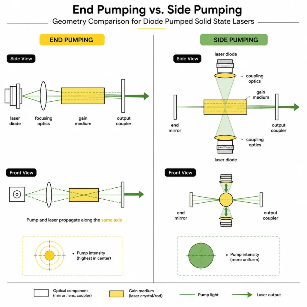
End pumping injects pump light along the resonator axis, so the pumped volume overlaps the laser mode closely, giving high efficiency and near-diffraction-limited beam quality but concentrating heat in a small volume. Side pumping fires diode bars radially into the rod, tolerating cheap low-brightness pumps and scaling to high power, at the cost of mode overlap and beam quality.
The two geometries, stated precisely
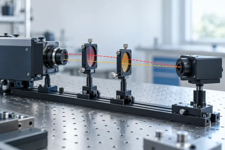
End pumping, also called longitudinal pumping, sends the pump beam in along the resonator axis, usually through a dichroic mirror that passes the pump and reflects the laser wavelength. Because you control where the pump goes, you can shape it to sit inside the resonator mode. Gain exists only where the laser mode is, so the mode competition that produces higher-order content never gets started.
Side pumping, or transverse pumping, injects light through the barrel of the rod, perpendicular to the axis. Pump beam quality stops mattering almost entirely, which means you can use bare diode bars and stacks with no coupling optics at all. Absorbed energy spreads along the full rod length instead of piling up at one face.
The classical guidance from the diode-pumped solid-state literature is to prefer end pumping below roughly 1 W of continuous output and to consider side pumping above roughly 10 W (Introduction to Laser Diode-Pumped Solid State Lasers). Notice the gap. Most OEM products live between 1 and 10 W, which is exactly the region that guidance declines to cover.
Why the crossover is not a fixed number
The 1 W and 10 W figures come from a specific set of assumptions: continuous operation, a Nd:YAG rod, commodity pump brightness, and a demand for good beam quality. Change any of those and the crossover moves.
Four things push it upward, meaning end pumping stays viable at higher power:
Pump brightness. A modern fiber-coupled module delivers around 30 W from a 200 µm core at 0.22 NA, enough to pump roughly 15 W out of a Nd:YAG or Nd:YVO₄ laser (RP Photonics). That is already well past the “consider side pumping” line.
In-band pumping. Moving from 808 nm to 885 or 888 nm cuts the heat you deposit per absorbed watt substantially, and stretches the crystal from 8 mm or less to 30 mm or longer, spreading the same heat over a longer volume.
Low duty cycle. A pulsed rangefinder pump running at a few percent duty cycle has an average thermal load an order of magnitude below a continuous marker at the same peak.
Composite crystals. An undoped end cap bonded to the doped section moves the peak heat density away from a free surface, which is where fracture starts.
Two things push the crossover down. A hard requirement for M² near 1 at full power leaves less thermal headroom before the resonator walks out of its stability zone. And a gain medium with low thermal conductivity or a large thermo-optic coefficient will lens earlier regardless of how well you pump it.
Treat the crossover as an output of your own thermal arithmetic, not an input.
Estimating the thermal lens before you build anything
The thermal lens is the single effect that ends most end-pumped designs, and you can bound it early.
The standard expression for dioptric power is 1/f = (∂n/∂T) · P_heat / (2κA), where A is the pumped area and κ the thermal conductivity (RP Photonics). Two details in that reference matter more than the formula itself. For a Gaussian pump profile the on-axis lens is about twice as strong as the uniform-area formula predicts, which is exactly the factor that makes a first build roll over earlier than the spreadsheet said. And Nd:YLF has a negative thermo-optic coefficient, so it produces a defocusing lens rather than a focusing one.
Rather than guessing material constants, work from a measured coefficient. A characterized end-pumped Nd:YVO₄ laser, pumped through a 200 µm 0.22 NA delivery fiber, showed a thermal lens of 0.24 m⁻¹ per watt of absorbed pump with a quasi-top-hat profile, and 0.17 m⁻¹ per watt when the pump was reshaped into a ring (University of Southampton).
Put numbers through it. At 20 W absorbed, the top-hat case gives 4.8 m⁻¹, a focal length near 21 cm. Reshaping to a ring gives 3.4 m⁻¹, about 29 cm. That difference is not cosmetic. A resonator designed for a 21 cm intracavity lens and a resonator designed for a 29 cm one have different stability margins, and one of them will still be in its stability zone at 30 W.
The same paper is worth reading for what it costs you: the top-hat configuration produced 9.8 W at 23.8 W absorbed with 57.3% slope efficiency and M² of 1.08, and beam quality degraded to roughly 1.3 as absorbed power approached 31 W. Beam quality does not fall off a cliff. It erodes, and it erodes with power.
The practical rule: compute the thermal lens at your maximum absorbed power, double it if your pump profile is Gaussian rather than flat, then check that the resonator remains stable at that value. If it does not, you have found your crossover point, and no amount of resonator tuning will move it.
Mode matching: the arithmetic nobody publishes
End pumping works because the pump volume sits inside the laser mode. Getting that right is a short calculation, and it is worth doing before you order optics.
Start from the resonator. A near-hemispherical cavity with a 10 cm mirror radius of curvature and 10 cm length gives a mode waist of roughly 75 µm in Nd:YAG (Introduction to Laser Diode-Pumped Solid State Lasers). That is your target.
Now the pump. A 200 µm core fiber relayed one-to-one puts a 200 µm diameter spot in the crystal, a 100 µm radius. Larger than the mode. Pump that sits outside the mode does two things, both bad: it wastes power, and it provides gain where higher-order modes live, which is how M² creeps up under load.
So you demagnify. A relay ratio near 0.7 brings the pump radius to roughly 70 µm, just inside the 75 µm mode waist. But demagnifying the spot magnifies the divergence by the same factor, so the pump now diverges faster and stays small over a shorter distance. If your crystal is longer than that distance, the pump expands beyond the mode in the back half of the crystal and you have recreated the original problem at the far end.
That coupling, between spot size, divergence and crystal length, is the real design constraint in end pumping. It is also why in-band pumping is awkward to retrofit: a 30 mm crystal needs the pump to stay collimated far longer than an 8 mm one does.
Confocal resonators produce mode waists too large for pump powers of several watts, which is why the near-hemispherical geometry keeps showing up in end-pumped designs.
Crystal length and doping are one decision, not two
Engineers routinely specify absorption fraction and crystal length independently, then wonder why the entrance face runs hot.
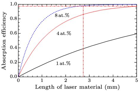
The numbers for Nd:YAG at 808 nm: peak absorption coefficient around 8 cm⁻¹, giving a 1.25 mm absorption length, and 98% absorption in 5 mm. At the half-maximum points of the absorption band the coefficient falls to roughly 4 cm⁻¹, and you need about 10 mm for better than 90% absorption. Standard doping to reach 8 cm⁻¹ is about 1.1%, and concentration quenching sets a practical ceiling near 1.5% (Introduction to Laser Diode-Pumped Solid State Lasers; IAAST DPSS overview).
Read those two absorption coefficients together. A crystal sized for 5 mm at the absorption peak will absorb far less if your diode drifts to the band edge, and the shortfall shows up as lost output that looks like a resonator problem. Sizing at 10 mm buys you tolerance to wavelength drift, at the cost of a longer path for the pump to stay confined.
Doping works the same way. Higher doping shortens the crystal and raises peak heat density at the entrance face. Lower doping spreads the heat but demands a longer crystal and tighter pump collimation. A published Nd:YVO₄ trade study across 1 to 5 at% and 1 to 5 mm lengths landed on 2 at% and 2 mm as optimum for its configuration, reaching 50.0% slope efficiency and 45.4% optical-to-optical. Notably, effective emission cross-section rose from 14.0 to 23.1 ×10⁻¹⁹ cm² between 1 and 3 at%, while upper-level lifetime fell from 105 to 85 µs. You buy gain and pay in storage.
The loop to run: target absorption fraction, then absorption coefficient, then doping, then length, then check peak heat density at the entrance face, then iterate.
Pump wavelength drift is a geometry decision
This is the connection almost nobody makes explicitly, and it may be the most useful thing in this article.
A diode’s emission wavelength moves with junction temperature at roughly 0.3 nm/°C, and holding a pump on the Nd:YAG band typically requires temperature control to better than about ±4 °C. Under pulsed operation the wavelength can shift transiently by around 5 nm, which exceeds the absorption linewidth of many gain media. The Nd:YAG absorption linewidth around 810 nm is roughly 2 nm (IAAST DPSS overview).
Now apply that to geometry. An end-pumped crystal sized at 5 mm for peak absorption has almost no margin: drift to the band edge halves your absorption coefficient and the 5 mm crystal no longer absorbs the pump. A side-pumped rod is 32 mm or longer with pump entering through the barrel, so the absorption path is generous and the same drift costs you far less.
Side pumping is more forgiving of wavelength drift, and that forgiveness is often worth more in a field-deployed product than the efficiency you give up. If your platform cannot carry a thermoelectric cooler, geometry and wavelength stability are the same conversation. Our 808 nm fiber-coupled pump modules and the longer-wavelength 888 nm series get specified differently for exactly this reason.
What each geometry actually costs
Published comparisons treat cost as if it were the diode price. It is not.
An end-pumped head carries: one fiber-coupled module, relay optics, a dichroic, a precision mount with angular adjustment, usually a temperature controller, and alignment labor on every unit. The parts count is low and the labor content is high. Yield losses concentrate in alignment and in crystal handling.
A side-pumped head carries: three or more diode bars or modules, a pump cavity or reflector, a cooling loop with seals and fittings, and very little pump optics. The parts count is higher, the alignment content is far lower, and the recurring risk moves into the cooling system. Coolant loops leak, corrode, and need service access.
For diode hardware itself, a single bar of the type used for side pumping runs about 1 cm long and delivers roughly 20 W continuous or 60 W pulsed, and two-dimensional stacks reach 300 to 1500 W/cm² at duty cycles between 3% and 20% (Laser Focus World).
If you are building tens of units a year, alignment labor is affordable and end pumping is attractive. At thousands of units, alignment labor is the dominant cost and anything that removes it wins.
Duty cycle changes the answer
A geometry choice made for continuous operation frequently does not survive contact with a pulsed product.
Side-pumped stack sources are routinely specified at 3% to 20% duty cycle. At 5% duty, average thermal load drops by a factor of 20, and the thermal lens with it. That can pull an end-pumped design back into feasibility at a peak power that would be impossible continuously, or make a side-pumped head far simpler to cool than its peak numbers imply.
Work your thermal arithmetic from average absorbed power, and your gain and extraction arithmetic from peak. Confusing the two is a common and expensive error.
When the answer is neither
Four options sit between the two geometries, and they deserve costing rather than a footnote.
In-band pumping at 885 or 888 nm. This is not only an efficiency play. Reducing the heat per absorbed watt is a way to *keep* end pumping at a power where you would otherwise have to abandon it. At 888 nm the a-axis and c-axis absorption in Nd:YVO₄ are nearly equal, which removes the polarization-handling optics that 878.6 nm and 885 nm designs need (Laser Focus World).
The bounce amplifier. A grazing-incidence geometry that side-pumps near a total-internal-reflection bounce, giving side-pump power levels with much better mode overlap. Underused, and worth evaluating before you accept side pumping’s beam quality.
Composite crystals. An undoped end cap diffusion-bonded to the doped section moves peak heat away from the free entrance face. It costs more per crystal and buys real thermal headroom in end-pumped designs.
Not building a rod laser at all. Fiber geometries are largely immune to thermal lensing until multi-kilowatt output (RP Photonics). If your specification is achievable in fiber, the honest answer is often that neither rod geometry is the right architecture. Our solid-state laser guide walks through where each architecture stops making sense.
Symptoms and what they usually mean
| What you observe | Most likely cause |
|---|---|
| Output rolls over above a certain drive current | Thermal lens has pushed the resonator out of its stability zone |
| M² degrades as power increases | Pump volume larger than mode volume; higher-order modes finding gain |
| Crystal entrance face cracks | Peak heat density too high; doping too high or pump spot too small |
| Power drops during the first minutes of operation | Pump wavelength drifting off the absorption peak as the diode warms |
| Polarization ratio degrades in a rod | Stress birefringence and depolarization loss |
| Beam is elliptical and astigmatic | Bifocusing; tangential and sagittal lens strengths differ |
How we approach geometry selection
Our engineering starts from the thermal budget rather than the catalog. Before recommending a pump module we want the absorbed power at the worst-case operating point, the beam quality the system actually needs (as opposed to the one the specification inherited), the duty cycle, and the ambient envelope. Those four numbers usually settle the geometry on their own.
On the manufacturing side, the reason we characterize delivered power at the fiber end rather than chip power is that end-pumped designs live or die on what actually arrives in the mode volume. Automated fiber coupling, hermetic sealing by parallel seam welding, burn-in screening, and full-window temperature cycling exist so that the number in your thermal model is the number you get in year three. That flow is the same whether you end up end pumping or side pumping, but end-pumped designs are far less tolerant of a supplier who quotes chip power.
Frequently asked questions
Is end pumping always more efficient than side pumping?
Usually, but not automatically. End pumping wins on efficiency because the pumped volume overlaps the laser mode closely. That advantage disappears if the pump spot is poorly matched to the mode, or if thermal lensing has moved the resonator toward the edge of its stability zone, where mode size changes with power.
At what power should I switch from end pumping to side pumping?
There is no universal number. Classical guidance suggests end pumping below about 1 W and side pumping above about 10 W continuous, but pump brightness, in-band pumping, low duty cycle and composite crystals all push the crossover higher. Compute the thermal lens at your maximum absorbed power and check resonator stability there.
Why is TEM₀₀ operation harder in a side-pumped laser?
Side pumping deposits gain across the whole rod cross-section, including the region outside the fundamental mode. Higher-order modes find gain there and start oscillating. End pumping confines gain to the mode volume, so the geometry itself acts as a mode filter.
How do I reduce thermal lensing in an end-pumped laser?
Spread the heat over a longer volume by pumping in-band at 885 or 888 nm with a longer crystal, lower the doping concentration, reshape the pump from Gaussian toward top-hat or ring, or bond an undoped end cap to move peak heat away from the entrance face. Each has a cost; none is free.
Does side pumping tolerate pump wavelength drift better?
Yes, and this is often the deciding factor for field equipment. Side-pumped rods present a much longer absorption path, so a diode drifting off the absorption peak costs proportionally less output than it would in a 5 mm end-pumped crystal.
Settle the geometry before the resonator
The order that saves time is: absorbed power at worst case, thermal lens estimate, resonator stability check, then geometry, then everything else. Reversing it produces a resonator that works on paper and rolls over on the bench.
Send us your gain medium, output requirement, duty cycle and environmental envelope, and our engineers will work the thermal arithmetic with you before anyone specifies a part number. Start a design review, or read the broader background on laser pumping if you are still mapping the options.
References
- Introduction to Laser Diode-Pumped Solid State Lasers — absorption coefficients, crossover guidance, resonator mode waist example
- RP Photonics Encyclopedia — Thermal Lensing, End Pumping, Side Pumping
- End-pumped Nd:YVO₄ laser with reduced thermal lensing — University of Southampton, measured dioptric power per watt
- Laser Focus World — Diode arrays boost efficiency of solid-state lasers and Enhance your Nd-doped DPSS laser with a longer-wavelength pump