

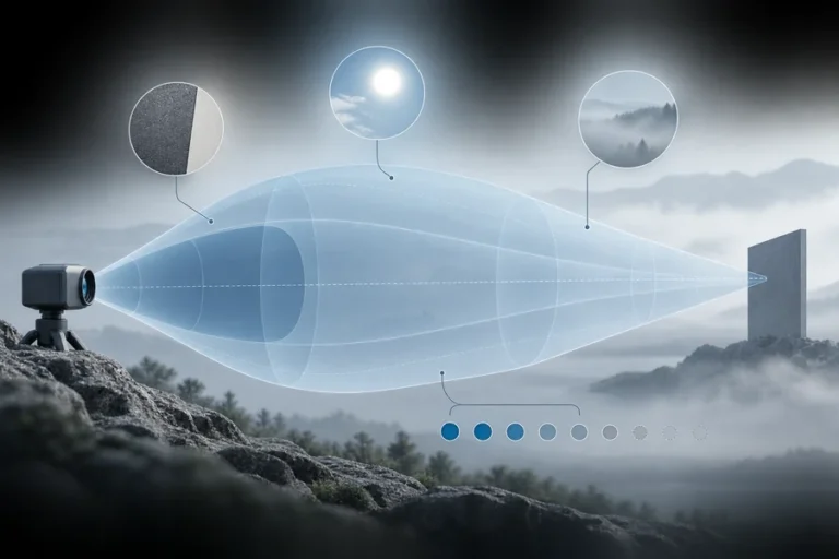

The thermoelectric cooler is the part of a pump module nobody wants and most designs end up carrying. It draws power you do not have on a UAV, occupies volume you do not have in a handheld unit, adds a control loop that can fail, and introduces solder joints that fatigue under thermal cycling on a vehicle.
So the question comes up in almost every design review: can we drop the TEC? And the answer is usually a shrug, because the published material splits into two camps that both avoid it. Encyclopedia pages state that diodes drift about 0.3 nm per degree and stop. Vendor pages explain the drift and then sell you a temperature controller. Neither tells you how to decide.
The decision is arithmetic. Add up every source of wavelength excursion in your system, compare the total against the width of the absorption feature you are pumping, and see whether what is left is a product or a problem. This article walks that calculation, then covers what to do when the number does not close.
Table of Contents
Pump diode emission wavelength shifts with junction temperature at roughly 0.2 to 0.35 nm/°C depending on the material system. TEC-less design works when the total wavelength excursion — ambient swing, self-heating, part-to-part binning and aging combined — stays within the gain medium’s absorption bandwidth, or when you deliberately accept output derating across temperature instead of controlling it.
Where the drift comes from
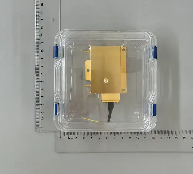
Two mechanisms move a diode’s emission wavelength as the junction heats: the semiconductor bandgap narrows, and the cavity expands. Both push the wavelength longer, and the combined coefficient is what appears on datasheets.
Typical laser diodes tune at approximately +0.3 nm/K (RP Photonics). A measured 940 nm device gave 0.335 nm/°C, linear from 20 to 70 °C (MKS/Newport AN30). A teaching-lab pump diode is documented at approximately 0.25 nm/K, with an additional current coefficient of about 0.05 nm/mA.
Coefficients vary by material system and cavity design. Fabry-Pérot broad-area emitters in the 900 to 1000 nm range sit around 0.28 to 0.33 nm/°C, AlGaAs devices in the 780 to 870 nm range around 0.20 to 0.30 nm/°C, while DFB and DBR structures come in far lower and grating-locked devices lower still. Treat those ranges as indicative and get the number for your specific part from its datasheet.
One point that gets lost: this is junction temperature, not case temperature and certainly not ambient. Junction sits above case by the dissipated power times the thermal resistance of everything between them.
The excursion budget nobody writes down
Most discussions treat drift as a single term. It is four, and they add.
Ambient or case temperature swing. Your specified operating range, multiplied by the coefficient.
Self-heating from threshold to full power. This is the term everyone forgets, and it is large. Measured on 180 W bars, wavelength shifts roughly 7 nm from threshold to full power, and single emitters can shift as much as 20 nm (Coherent, Diode Pump Requirements for High Power Fiber Lasers). That is bigger than many ambient budgets.
Part-to-part binning. Suppliers bin center wavelength within a stated window. Whatever that window is, it consumes budget on every unit you build.
Aging drift. QCW bar life tests recorded wavelength shifts from 0.01 to 3.15 nm over life (NASA GSFC). A design that closes on day one and not in year five has not closed.
Work a case. Suppose a modest 0 to 50 °C case range, an emitter at 0.3 nm/°C, a bar-class package, and a datasheet binning window of ±1.5 nm.
| Term | Contribution |
|---|---|
| Case temperature swing, 50 °C × 0.3 nm/°C | 15 nm |
| Self-heating, threshold to full power | ~7 nm |
| Binning window | 3 nm |
| Aging over life | up to ~3 nm |
| Total excursion | ~28 nm |
That is the honest number. Now it has to be compared with something.
Compare it against the absorption feature, not against a feeling
The comparison is what makes the decision, and it changes completely depending on which band you pump.
Nd:YAG at 808 nm has an absorption linewidth around 2 nm (IAAST DPSS overview). A neighboring peak near 805 nm extends the useful region, giving an effective absorption width of about 5.5 nm (Cutting Edge Optronics).
Set 28 nm of excursion against 5.5 nm of absorption width and the answer is unambiguous: a broad-temperature, unlocked, uncooled 808 nm pump into Nd:YAG does not work. No amount of clever biasing fixes a five-to-one mismatch. Anyone who tells you otherwise has not added up the terms.
That is not a reason to abandon TEC-less design. It is a reason to change one of the three inputs: narrow the temperature window, lock the wavelength, or pump a wider absorption feature.
Broad versus narrow absorption is a thermal decision
The literature frames pump wavelength choice almost entirely as an efficiency question. Reframe it as a thermal-control question and the ranking changes.
| Pump band | Gain medium | Absorption character | TEC-less friendliness |
|---|---|---|---|
| 808 nm | Nd:YAG, Nd:YVO₄ | Narrow, strong; ~5.5 nm effective width | Poor. Needs locking or tight temperature control |
| 885 / 888 nm | Nd:YAG, Nd:YVO₄ | Weak but broad and flat; 888 nm is nearly polarization-independent | Good. The main reason to accept a longer crystal |
| 915 nm | Yb-doped fiber | Broad, flat shoulder | Good. Commonly used unlocked |
| 976 nm | Yb, Er:Yb fiber | Narrow, very strong; peak absorption roughly 3× the 915 nm value in aluminosilicate fiber and about 5× in phosphosilicate | Poor without stabilization |
Absorption cross-sections in Nd:YVO₄ show how steep the trade is: 321 at 808 nm against 108 at 880 nm, 9.5 at 888 nm and 4.12 at 914 nm, in units of 10⁻²¹ cm² (NASA technical manuscript.pdf)). Weak absorption is the price of a forgiving band, and you pay it in crystal or fiber length. Moving from 808 nm to the 880 nm region takes a crystal from 8 mm or less to 30 mm or more (Laser Focus World).
For an uncooled design, that length is often a bargain. A 915 nm pump into ytterbium fiber tolerates the kind of excursion budget calculated above in a way a 976 nm pump simply does not. Our post on pump wavelength selection works the quantum-defect side of the same choice.
Wavelength biasing: aim at the corner that matters
If your excursion budget is close to the absorption width rather than five times it, biasing is the move.
Specify the nominal 25 °C wavelength deliberately *short*, so that the diode lands on the absorption peak at the hottest operating point you actually care about, and sits on the short-wavelength side of the band when cold. You are not eliminating drift. You are choosing where in the temperature range you spend your best absorption.
Which corner deserves the peak depends on the mission. A vehicle system that must hold range specification on a hot day biases hot. A system whose worst case is a cold start biases cold. A system that must meet the same specification at both ends needs locking, and finding that out during the budget exercise is far cheaper than finding it out during qualification.
State the bias explicitly in the purchase specification. A supplier asked for “808 nm” will give you 808 nm at 25 °C, which is almost never what you meant.
Grating locking and cooling, compared in the same units
The two engineered fixes rarely get compared honestly, because each is usually discussed by someone selling it.
Volume Bragg grating locking narrows the spectrum and pins it against temperature. On a kilowatt-class array, adding VBGs narrowed the wavelength distribution from 2.7 nm FWHM to 0.7 nm FWHM and reduced output power at 80 A by about 8% (Cutting Edge Optronics). The same source measured wavelength shift with drive current dropping from 0.05 nm/A unstabilized to 0.008 nm/A with gratings, so locking suppresses the current term as well as the temperature term.
So the grating costs roughly 8% of your optical power, plus part cost, plus an added alignment-sensitive element that has to survive vibration.
A TEC costs electrical power that scales badly with the temperature difference it must maintain, volume, mass, a control loop, and a component whose solder joints fatigue under exactly the thermal cycling your product experiences. On a UAV it must also reject heat into air that is already hot, which is the condition where a Peltier device performs worst.
The honest comparison is 8% optical power against the TEC’s power draw and reliability burden in your specific thermal environment. There is no universal winner. There is a calculation, and it is usually worth doing on paper before either part is selected.
Fiber Bragg grating stabilization achieves the same end in a fiber pigtail rather than free space. Uncooled, FBG-stabilized pump modules are commercially established: one telecom-class 980 nm module holds its wavelength within a 4 nm window across a case temperature range of −40 to +85 °C with no TEC and typical power consumption below 1 W (Coherent datasheet). That is a milliwatt-class telecom part rather than a high-power pump, so do not read across the numbers. Read across the principle: locked and uncooled across 125 °C is a shipping product category, not a research result.
IMAGE PLACEHOLDER — replace before publishing
IMAGE PLACEHOLDER #2
Product/asset to show: Stacked bar chart of the wavelength excursion budget (case swing, self-heating, binning, aging) with a horizontal band overlaid showing absorption width for 808 nm, 885/888 nm and 915 nm.
Design direction: Horizontal stacked bar, white background, LUMEXIS palette. One bar for total excursion. Three shaded horizontal bands to its right representing each absorption feature’s width, clearly labeled. Annotate “budget must fit inside the band”.
What it must communicate: The TEC-less decision is a single comparison between two numbers, and the pump band you choose moves one of them.
Suggested filename: lumexis-pump-diode-wavelength-drift-tec-less-2.webp
Alt text: Wavelength excursion budget compared against absorption bandwidth at 808, 888 and 915 nm
Derate instead of control
The option missing from most discussions: accept that output falls at the hot corner, and design the system to meet its requirement there anyway.
This is how field equipment actually gets built. Size the pump at the worst-case ambient, verify the system meets specification at that point, and let it overperform when cold. Publish an output-versus-ambient curve rather than a single number, and set the acceptance test at the corner rather than at 25 °C.
The reason it works is that most missions do not require constant output. A rangefinder needs to reach its specified range at 55 °C; it does not need to produce identical pulse energy at 55 °C and at −20 °C. Once you stop defending a constant number, a surprising amount of thermal hardware becomes unnecessary.
Duty cycle helps here more than anything else. A pulsed pump running at a few percent duty has an average dissipation an order of magnitude below a continuous one, which shrinks the self-heating term and the junction-to-case rise together. Low-duty-cycle systems such as UAV ranging and altimetry payloads are the easiest TEC-less problems there are.
Cold start is a separate problem
A design that closes in steady state can still fail in the first seconds.
Power on at −30 °C and the junction heats rapidly while the chassis stays cold. The emission wavelength sweeps through part of the absorption band during that transient, so output climbs, peaks, and settles somewhere else. For a rangefinder that must produce a valid measurement on the first trigger pull, this is a functional requirement, not a curiosity.
Three mitigations are worth designing in. A brief pre-bias current that warms the junction before the first shot. Firmware that derates or delays the first pulses based on a thermistor reading. Or simply specifying first-shot accuracy separately from steady-state accuracy, and testing it.
Current as a trim knob
Drive current shifts wavelength too, around 0.05 nm/mA on a single emitter and about 0.05 nm/A on an unstabilized array. That is a control input, not only an error source.
You can nudge wavelength onto the absorption peak by adjusting current, at the cost of output power. No moving parts, no Peltier, and it can be closed-loop from a thermistor in firmware. It will not cover 28 nm of excursion, but it will cover the last nanometre or two, which is often exactly what stands between a design that closes and one that does not.
When TEC-less is the wrong answer
Three cases where the honest recommendation is to keep the cooler or accept locking:
High-power 976 nm pumping where the narrow peak is the whole point, and moving to 915 nm would demand more fiber than the package allows. Systems with a hard spectral requirement, such as narrow-line pumping for a specific transition. And any design where the total excursion exceeds the absorption width by more than roughly a factor of two, where biasing and current trim together cannot close the gap.
Drawing that line early is cheaper than discovering it in qualification.
How to write the specification
Most uncooled pump programs fail at the purchase order, not at the physics. Specify it this way:
Center wavelength as a window guaranteed across the full case-temperature range, not a value at 25 °C. State the case temperature range and the thermal interface you will provide, including mounting flatness and interface material. State spectral width with the measurement convention named, since FWHM, 90% power content and −13 dB widths are not interchangeable. State minimum optical power at the hot corner, at the fiber end. State the pulse format and duty cycle. State whether wavelength locking is required, and what optical power penalty is acceptable if it is. Require the wavelength-versus-temperature and power-versus-temperature curves as deliverables, not just endpoint numbers.
A supplier who can quote against that specification has characterized the part across temperature. A supplier who can only quote a 25 °C number has not.
How we approach it
TEC-less operation is one of the competencies our team designs around, because the platforms we serve most often — UAV, vehicle-mounted and handheld — pay a real penalty for every watt and every cubic centimetre. The approach is the one described above: build the excursion budget first, choose the pump band to fit it, bias the nominal wavelength at the corner that matters for the mission, and derate deliberately rather than fighting to hold a constant number.
The manufacturing side supports that. High and low temperature cycling across the full operating window before final test is what turns a wavelength-versus-temperature curve from a modeling assumption into a measured deliverable. It is also the only way to know whether the fiber and its termination survive the same cycling the diode does.
Frequently asked questions
How much does laser diode wavelength shift per degree C?
Typically around 0.3 nm/°C for Fabry-Pérot pump diodes, with the range spanning roughly 0.2 to 0.35 nm/°C depending on material system. DFB, DBR and grating-locked devices are far lower. The coefficient applies to junction temperature, which sits above case temperature by the dissipated power times thermal resistance.
Can you run a pump diode without a TEC?
Yes, when the total wavelength excursion fits inside the gain medium’s absorption bandwidth, or when you accept output derating across temperature. It becomes straightforward with broad absorption features such as 915 nm into ytterbium or 885/888 nm into neodymium, and difficult at 808 nm or 976 nm without wavelength locking.
What is the absorption bandwidth of Nd:YAG at 808 nm?
The main absorption linewidth is around 2 nm, and a neighboring peak near 805 nm extends the useful region to an effective width of roughly 5.5 nm. That effective width is what your wavelength excursion budget must fit inside.
How much output power does a volume Bragg grating cost?
On a measured kilowatt-class array, adding VBGs reduced output at 80 A by about 8% while narrowing the spectrum from 2.7 nm to 0.7 nm FWHM. Expect a single-digit percentage penalty as a planning figure and confirm it for your specific device.
Does the diode’s wavelength also change with drive current?
Yes, roughly 0.05 nm/mA on a single emitter and about 0.05 nm/A on an unstabilized array, dropping to around 0.008 nm/A when grating-stabilized. Current can be used deliberately as a fine wavelength trim, trading a little output power for better absorption overlap.
Why is 915 nm easier to run uncooled than 976 nm?
The ytterbium absorption feature at 915 nm is broad and flat, while the 976 nm peak is narrow and roughly three to five times stronger depending on fiber composition. The narrow peak gives shorter fiber and better efficiency but leaves almost no room for wavelength excursion.
Build the budget before you buy the cooler
Add the four excursion terms, compare the total against the absorption width of the band you intend to pump, and only then decide between a TEC, a grating and a derating curve. Doing it in that order takes an afternoon and regularly removes a component from the bill of materials.
Send us your operating temperature range, duty cycle, gain medium and power requirement, and our engineers will work the excursion budget with you and tell you honestly whether TEC-less closes. Start that conversation, or read the wider context in our guide to laser pumping.
References
- RP Photonics Encyclopedia — Wavelength Tuning and Volume Bragg Gratings
- Coherent — Diode Pump Requirements for High Power Fiber Lasers
- kW-class Wavelength Stabilized Laser Diode Arrays — VBG narrowing and power penalty, Nd:YAG effective absorption width
- MKS / Newport Application Note 30 — Measuring High Power Laser Diode Junction Temperature and Package Thermal Impedance
- Stephen & Krainak, NASA Goddard — Quasi-CW Laser Diode Bar Life Tests — wavelength drift over device life