
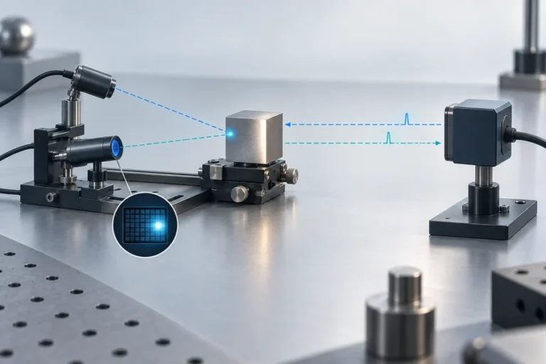

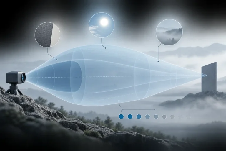
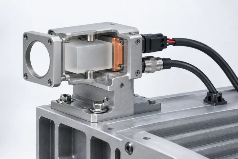
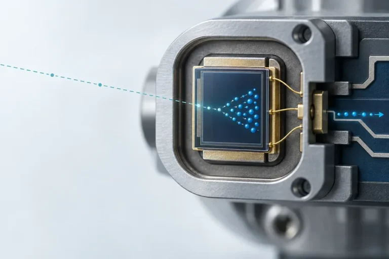



Optical crosstalk rangefinder errors occur when the receiver collects light that did not follow the intended target-return path. A cover window, internal surface, nearby optical channel, or poorly controlled enclosure reflection can create an early or extra signal that distorts a time-of-flight measurement.
Lumexis develops laser rangefinder modules for civil, industrial, and research integration. The module is only one part of the optical system; enclosure and window decisions can materially affect real-world measurement behavior.
Optical crosstalk rangefinder errors begin at integration
A rangefinder is designed to emit an optical pulse and process light returned from the intended target. In a finished instrument, the module may sit behind a protective window, near mechanical features, or beside other optical components. Any of these can introduce a short internal path to the receiver.
The result is not always an obvious communication fault. The host can receive a well-formed message containing a biased, unstable, or condition-dependent result. That is why optical crosstalk should be considered during mechanical and optical architecture, not only after software integration.
The most common contributors
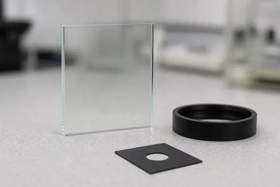
Potential contributors include a window surface placed in an unfavorable geometry, uncoated or contaminated internal surfaces, a reflective mechanical aperture, incomplete separation between transmit and receive paths, and unwanted light from nearby optical equipment. The specific risk depends on the module, wavelength, field of view, window material, and enclosure geometry.
Use a structured review rather than assuming a dark enclosure is sufficient:
| Area | Review question |
|---|---|
| Cover window | Does its angle, spacing, and finish create a path back to the receiver? |
| Apertures and baffles | Do they block unintended paths without clipping the intended field? |
| Interior finish | Are nearby surfaces controlled for low reflection and cleanliness? |
| Alignment | Are transmit and receive axes positioned as the system design expects? |
| Adjacent optics | Can another active channel reach the receiver during a measurement? |
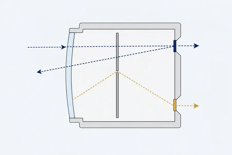
Test before and after adding the window
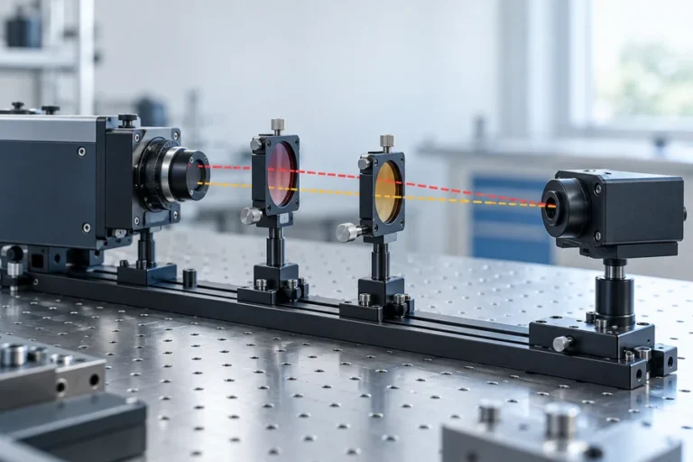
The clearest diagnostic is a controlled before/after comparison. Characterize the module in an open reference configuration, then repeat the same target and timing test with the planned window and enclosure. Change one variable at a time: window material, angle, spacing, aperture, surface finish, or nearby channel timing.
Record both the reported distance and any available signal-quality indicators. Test near and far conditions, target materials relevant to the application, and a dark or absorptive reference scene. A result that changes only after a window is installed is an important clue, but it still requires a disciplined investigation rather than a blanket correction.
For the baseline measurement principle, see time-of-flight distance measurement. For a wider system test sequence, read how to read a laser rangefinder module datasheet.
Design controls that help
The most durable remedy is to prevent unwanted light from reaching the receiver. Depending on the system, that can mean adjusting the window geometry, adding a controlled aperture or baffle, improving internal surface treatment, separating optical paths, or coordinating the timing of adjacent channels. Any proposed control should be verified on the actual mechanical stack-up.
Calibration can be useful when the optical arrangement is stable and the module’s documented behavior supports it. It should not be used to conceal an enclosure that changes after assembly, service, contamination, or temperature exposure. Production quality requires a design that remains predictable, not merely a correction that worked once on a bench.
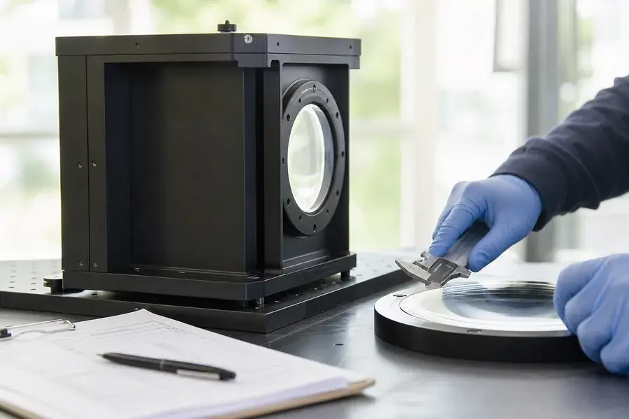
Bring optical review into the OEM workflow
Include the window and enclosure as controlled parts of the interface. Review mechanical drawings, prototypes, assembly tolerances, service cleaning, and final validation together. Our guide to laser rangefinder module datasheets can help teams identify the module conditions that need to be carried into system tests.
Lumexis engineers approach rangefinder integration as an optical, electrical, and manufacturing problem at once. Explore our applications or contact us to discuss a module and enclosure evaluation plan.
Control contamination and assembly variation
Optical behavior can change after assembly if a window is contaminated, a gasket is displaced, or a mechanical tolerance changes the gap and alignment. Define inspection points for these conditions and include a system-level check after final assembly. This requires a stable reference setup and a defined pass/fail method that represents the completed optical stack.
Use an optical crosstalk rangefinder review at design gates
Bring the optical, mechanical, and test owners together at each design gate. Review the window drawing, aperture stack, material finish, assembly tolerances, and test evidence as one system. Ask whether the same unwanted path could appear after normal production variation or service. If the answer is uncertain, create a small controlled experiment before committing to tooling. This approach is usually more efficient than searching for a firmware correction after the enclosure is complete.
Technical reading: ST’s cover-window guidance documents how cover-window reflections can distort ToF data; it is used here as technical reference only.
FAQ
What is optical crosstalk in a rangefinder?
It is unwanted light reaching the receiver through a path other than the intended target reflection. Internal window reflections, enclosure surfaces, nearby optical channels, and imperfect path separation can all contribute.
Can a protective window cause a distance bias?
Yes. A window can introduce reflections or change the optical path if its geometry, material, finish, spacing, or alignment is not compatible with the design. Test the complete optical stack rather than the bare module alone.
Is calibration enough to solve crosstalk?
Calibration can help in a stable, documented configuration, but it is not a substitute for preventing a strong or variable internal optical path. First reduce the source of unwanted light, then validate any calibration approach.
When should crosstalk testing happen?
Start during enclosure and window prototyping, then repeat with production-representative parts. Waiting until final integration makes the root cause harder and more expensive to isolate.