
خياران لمصادر 1.5 ميكرومتر لبنى ليدار واستشعار محددة.
منصة مصادر OEM بطول موجي 1535 نانومتر و1550 نانومتر
ليزر نبضي مقترن بالألياف لـ LiDAR
تطور لوميكسيس ألياف ليزر نابضة نانوية مدمجة لـ الليدار, الاستشعار عن بُعد، رسم الخرائط، الفحص الصناعي والأدوات العلمية. تشمل مجموعة المنتجات الحالية مصادر مدمجة بطول 1535 نانومتر و1550 نانومتر، وألياف ليزر عالية الذروة، ومصدر ضوء ليدار بثماني قنوات. تمتد المواصفات المنشورة من طاقة ذروة تتراوح بين 1.16 كيلوواط حتى 15 كيلوواط، وتكرار من 1 إلى 3000 كيلوهرتز، وعرض نبضة من 1 إلى 60 نانوثانية، وإخراج ضوئي عبر FC/APC أو FC/UPC أو ألياف متعددة الأوضاع.
طاقة الذروة، متوسط الطاقة، معدل التكرار وعرض النبضة تعتمد على التكوين. تأكد من ورقة بيانات النموذج المحدد قبل تثبيت التصميم البصري أو الكهربائي أو الحراري.
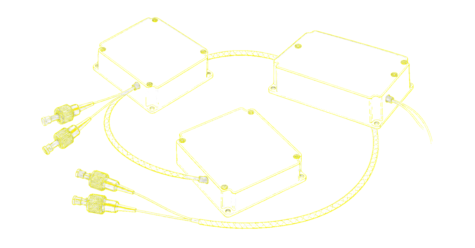
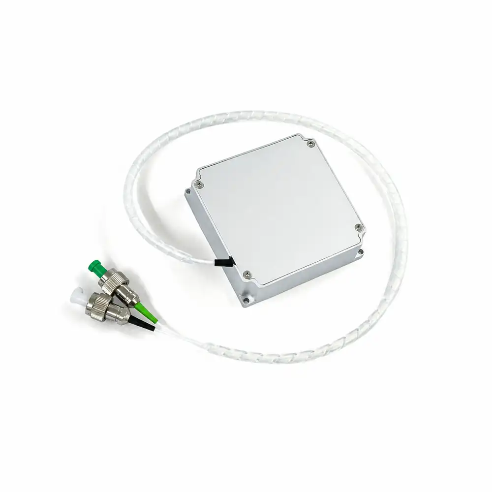 1535 نانومتر / 1.2 كيلوواط
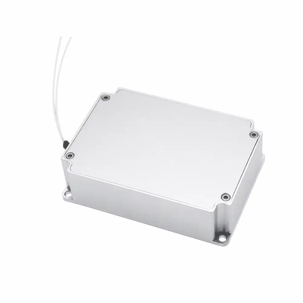 1550 نانومتر / 1.6 كيلوواط
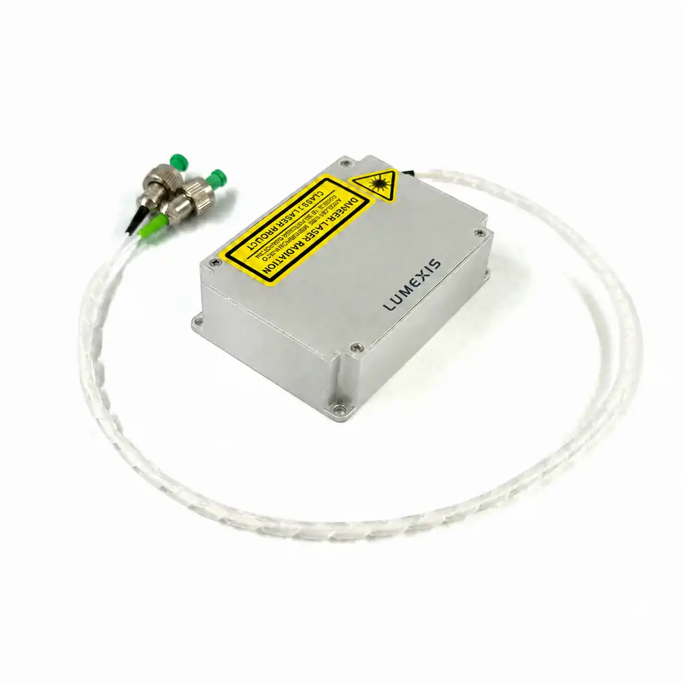 1550 نانومتر / 3 كيلوواط
فئات طاقة الذروة المنشورة من بنى مصادر مدمجة إلى عالية الطاقة.
إعدادات نبضة نانوية تعتمد على النموذج والتكوين.
نطاق التكرار المنشور عبر أرشيف المنتجات الحالي.
خيار الموصل يعتمد على النموذج؛ تحقق من المواصفات المحددة.
النطاق المنشور للسلسلة؛ تأكد من الحدود الحرارية الفعلية للمضيف.
مجموعة المنتجات الكاملة
اختر المصدر بناءً على ظروف النبضة وبنية الليدار النهائية.
طاقة الذروة وحدها لا تحدد أداء النظام. قارن الطول الموجي، عرض النبضة، معدل التكرار، ميزانية متوسط الطاقة، نوع الموصل والواجهات الميكانيكية/الحرارية قبل إصدار التصميم.
1535-LXMC1.2KW
ليزر ألياف نابض بقدرة 1.2 كيلوواط عند 1535 نانومتر
100 / 500 / 2000 كيلوهرتز؛ 2.5 / 3 / 3.5 نانوثانية؛ متوسط طاقة 1.2 واط؛ FC/APC + FC/UPC.
1550-LXMC1.6KW
ليزر ألياف نابض بقدرة 1.6 كيلوواط عند 1550 نانومتر
100 / 500 / 2000 كيلوهرتز؛ 2.5 / 3 / 3.5 نانوثانية؛ متوسط طاقة 2.1 واط؛ FC/APC.
1550-LXMC3KW
1550nm 3kW ليزر الألياف النبضي
50 / 500 / 2000 كيلوهرتز؛ 3 / 3 / 5 نانوثانية؛ متوسط طاقة 2.0 واط؛ FC/APC.
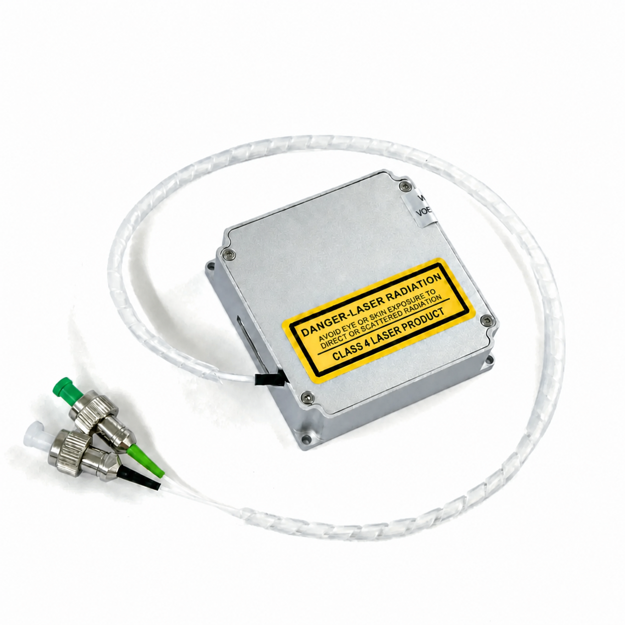
نبضي 1535 نانومتر
ليزر ألياف نابض عند 1535 نانومتر
3 نانوثانية نموذجي؛ 100–2000 كيلوهرتز قابل للتعديل؛ متوسط طاقة 0.7–1.1 واط؛ FC/APC + FC/UPC.
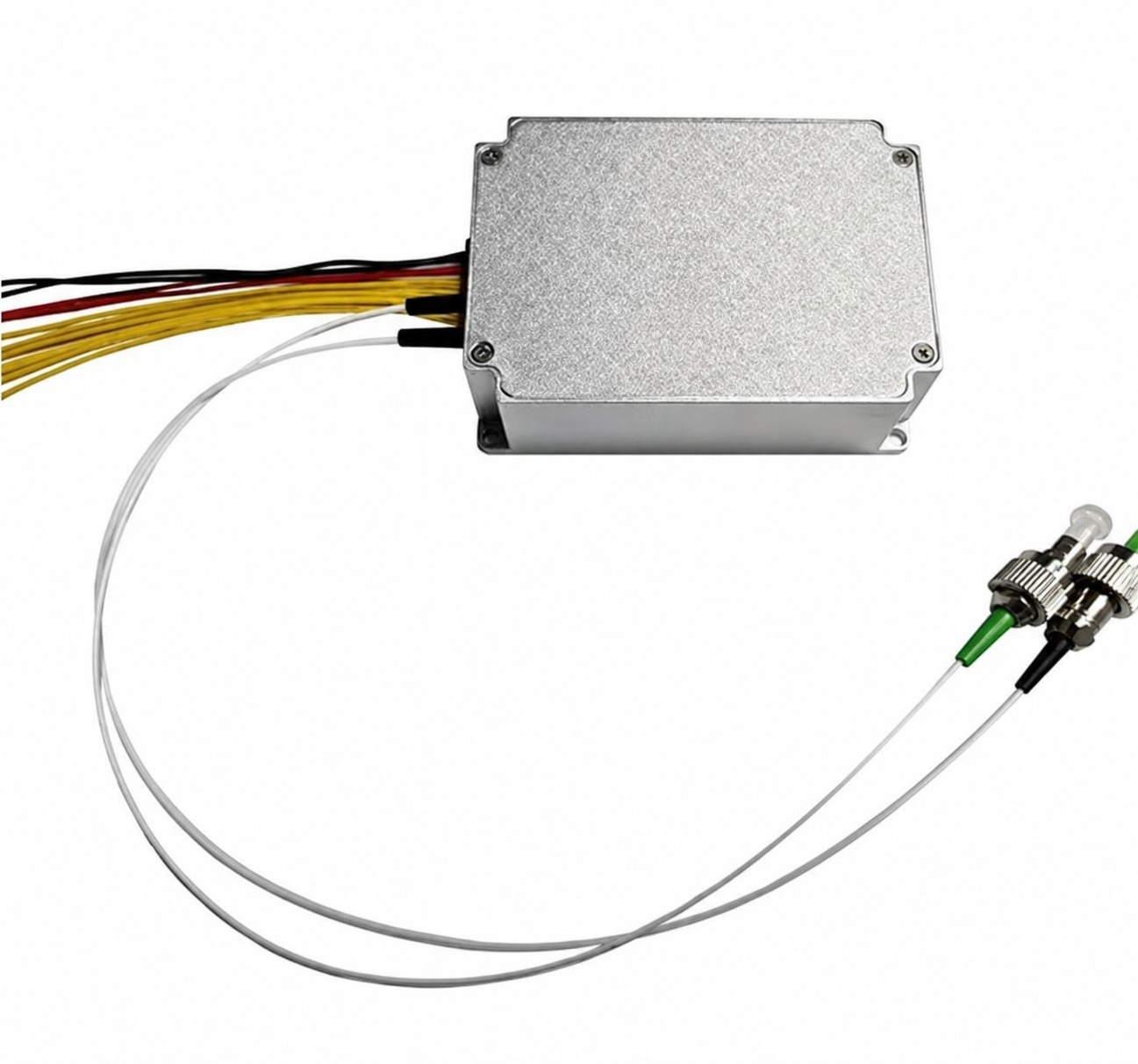
مدمج 1550
ليزر ألياف نابض مضغوط عند 1550 نانومتر
5 ميكروجول؛ 1–10 نانوثانية قابل للتعديل؛ 0.1–2 ميغاهرتز؛ FC/APC.
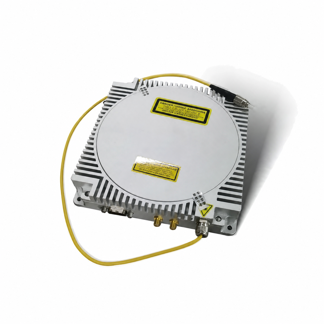
عالي الذروة 1550
ليزر ألياف عالي ذروة القدرة عند 1550 نانومتر
4 نانوثانية؛ 30–100 كيلوهرتز؛ متوسط طاقة 3–6 واط؛ إخراج ألياف متعددة الأوضاع.
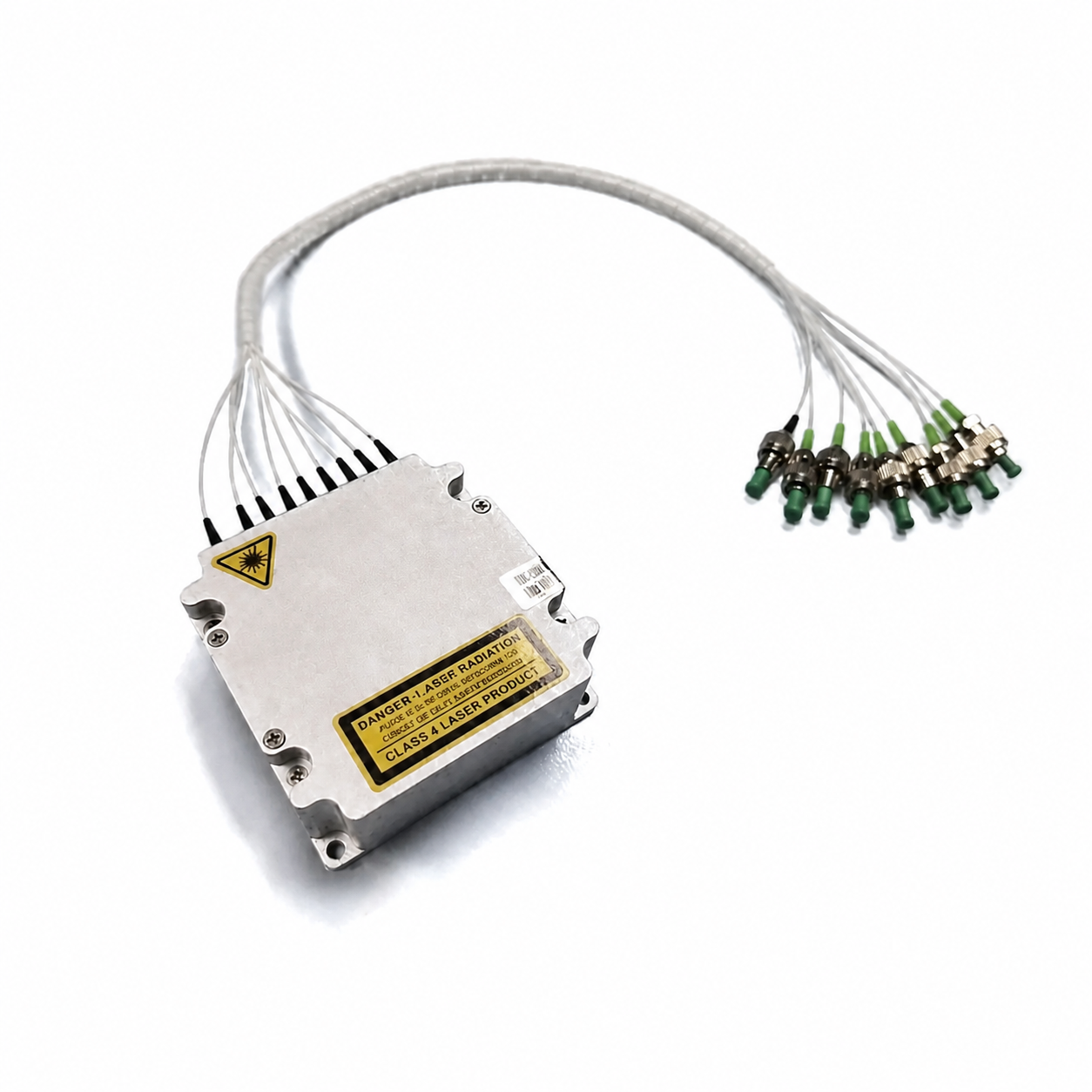
1550 8-في-1
مصدر ضوء LiDAR 8 في 1 عند 1550 نانومتر
بنية مصدر متكاملة متعددة القنوات؛ معدل التكرار والواجهة يُراجعان حسب التطبيق.
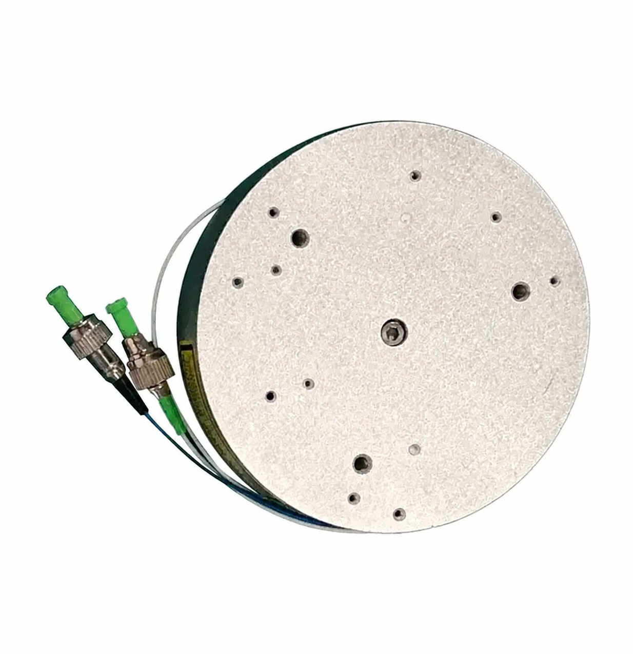
إربيوم 1550
ليزر ألياف الإربيوم النابض عند 1550 نانومتر
5 ميكروجول عند 100 كيلوهرتز / 3 نانوثانية؛ 1–60 نانوثانية؛ 1–3000 كيلوهرتز؛ FC/APC.
مقارنة النماذج
قارن المعلمات التقنية المنشورة في جدول واحد.
الأرقام أدناه هي قيم الاختيار المنشورة محليًا. تحدد المواصفات التقنية الخاصة بالطلب نقطة التشغيل النهائية والواجهة وشروط القبول.
| النموذج | الطول الموجي | ذروة القدرة | إعدادات التكرار | إعدادات عرض النبضة | متوسط القدرة | الإخراج البصري | الأبعاد | درجة حرارة التشغيل. |
|---|---|---|---|---|---|---|---|---|
| 1535-LXMC1.2KW | 1535 نانومتر | 2 كيلوواط | 100 / 500 / 2000 كيلوهرتز | 5 / 3 / 3.5 نانوثانية | 2 واط | FC/APC + FC/UPC | 55 × 55 × 16 مم | من -40 إلى +75 درجة مئوية |
| 1550-LXMC1.6KW | 1550 نانومتر | 6 كيلوواط | 100 / 500 / 2000 كيلوهرتز | 5 / 3 / 3.5 نانوثانية | 1 واط | FC/APC | 50 × 70 × 19 ملم | من -40 إلى +75 درجة مئوية |
| 1550-LXMC3KW | 1550 نانومتر | 3 كيلوواط | 50 / 500 / 2000 كيلوهرتز | 3 / 3 / 5 نانوثانية | 0 واط | FC/APC | 50 × 70 × 19 ملم | من -40 إلى +75 درجة مئوية |
| 1535 نانومتر نابض | 1532–1537 نانومتر | 1160 واط | 100–2000 كيلوهرتز | 3 نانو ثانية نموذجي | 7–1.1 واط | FC/APC + FC/UPC | 55 × 55 × 16 مم | −40 إلى +85 درجة مئوية |
| 1550 نانومتر مدمج | 1547–1553 نانومتر | 1–2 كيلوواط | 1–2 ميغاهرتز | 1–10 نانوثانية | 95–1.05 واط | FC/APC | 50 × 70 × 19 ملم | −40 إلى +70°م |
| 1550 نانومتر ذروة عالية | 1545–1555 نانومتر | 12 كيلوواط نموذجي؛ حتى 15 كيلوواط | 30–100 كيلوهرتز | 4 نانو ثانية | 3–6 واط | ألياف متعددة الأنماط | 160 × 160 × 30 مم | −40 إلى +60°م |
| 1550 نانومتر إربيوم | 1545–1555 نانومتر | 2 كيلوواط | 1–3000 كيلوهرتز | 1–60 نانوثانية | 8 واط | FC/APC | Ø90 × 24.5 ملم | −40 إلى +70°م |
ملاحظة المواصفات: الإمداد هو 9 / 12 / 13 فولت لجميع الطرازات الثلاثة المدرجة. تمثل قيم النبض والتكرار إعدادات التكوين المدرجة، وليست ضمانًا بأن كل مجموعة متاحة. قم بتأكيد الاختيار مع هندسة Lumexis.
نبضة بصرية نانوثانية
نبضة البذرةمضخم أليافتشكيل النبضةمخرج ألياف
أساسيات ليزر الألياف النابض
من نبضة البذرة إلى مخرج ليدار عبر الألياف.
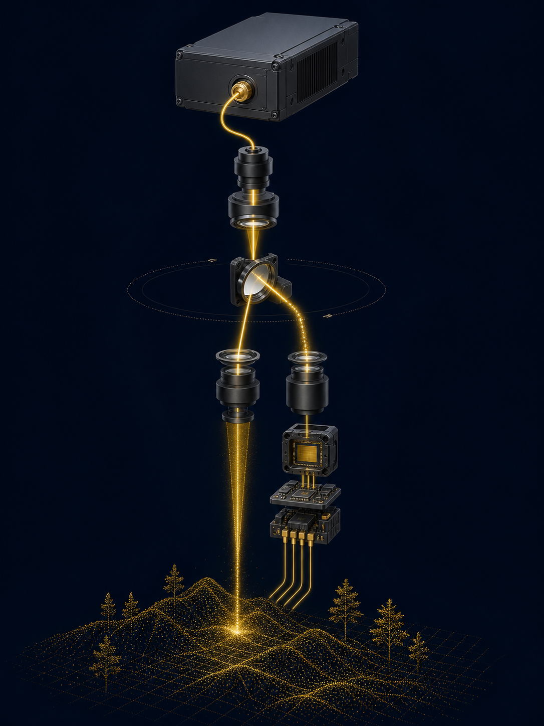
ينشئ ليزر الألياف النابض شكل موجة بذرة محكمًا ويضخمه عبر مسار كسب قائم على الألياف. يجب اختيار عرض نبضة الخرج، وقوة الذروة، ومعدل التكرار، ومتوسط الطاقة معًا لأنها تحدد توصيل الطاقة الضوئية، والحمل الحراري، وهامش التوقيت لنظام الاستشعار النهائي.
توقيت النبضة
تحدد البذرة المرجع الزمني وشكل النبضة الابتدائي للنظام.
مسار كسب الألياف
يرفع التضخيم النبضة الضوئية إلى فئة قوة الذروة المطلوبة.
واجهة الموصل
يجب أن يتطابق اختيار موصل الألياف مع بصريات المضيف، والتحكم في التلوث، واحتياجات الخدمة.
تشغيل خارجي
يجب التحقق من توقيت المضيف، والتأريض الكهربائي، وسلوك المشغل معًا.
معرفة الاختيار
تحدد أربع معلمات مترابطة غلاف النبضة القابل للاستخدام.
يتم اختيار هذه المصادر كجزء من نظام بصري. استخدم المستقبل الفعلي، وهندسة المسح، وفقدان البصريات، والمسار الحراري، وتوقيت اكتساب البيانات عند اختيار طراز ونقطة تشغيله.
هامش الإشارة
تؤثر قوة الذروة على الكثافة الضوئية المتاحة أثناء النبضة. قم بتقييمها مع حساسية المستقبل، وفقدان البصريات، وتقييم سلامة المضيف.
دقة التوقيت
يساهم عرض النبضة في دقة زمن الطيران، بينما تعتمد النتيجة العملية للنظام أيضًا على الكاشف والإلكترونيات ومعالجة الإشارات.
كثافة النقاط
يؤثر معدل التكرار على إيقاع القياس، وكثافة العينات، وإنتاجية البيانات، والحمل الحراري الكلي في الأداة النهائية.
الميزانية الحرارية
متوسط القدرة الضوئية والمدخلات الكهربائية يحددان متطلبات التبريد وإمداد الطاقة. لا تقم بحجم المسار الحراري بناءً على القدرة القصوى وحدها.
طاقة النبضة ≈ القدرة القصوى × عرض النبضة
استخدم وحدات متسقة: 1 كيلوواط × 1 نانوثانية ≈ 1 ميكروجول. هذه علاقة اختيار من الدرجة الأولى؛ يجب أخذ طاقة النبضة الفعلية المسلّمة ومجموعات التشغيل المتاحة من المواصفات الفنية للنموذج المختار.
حلول التطبيقات
مصمم لبنى LiDAR المدنية والصناعية والعلمية.
يأتي أداء التطبيق من الجهاز بأكمله: المصدر، بصريات الإرسال، الماسح الضوئي، المستقبل، إلكترونيات التوقيت، المعايرة وبيئة التشغيل. نحن ندعم اختيار النموذج حول تلك السلسلة الكاملة.
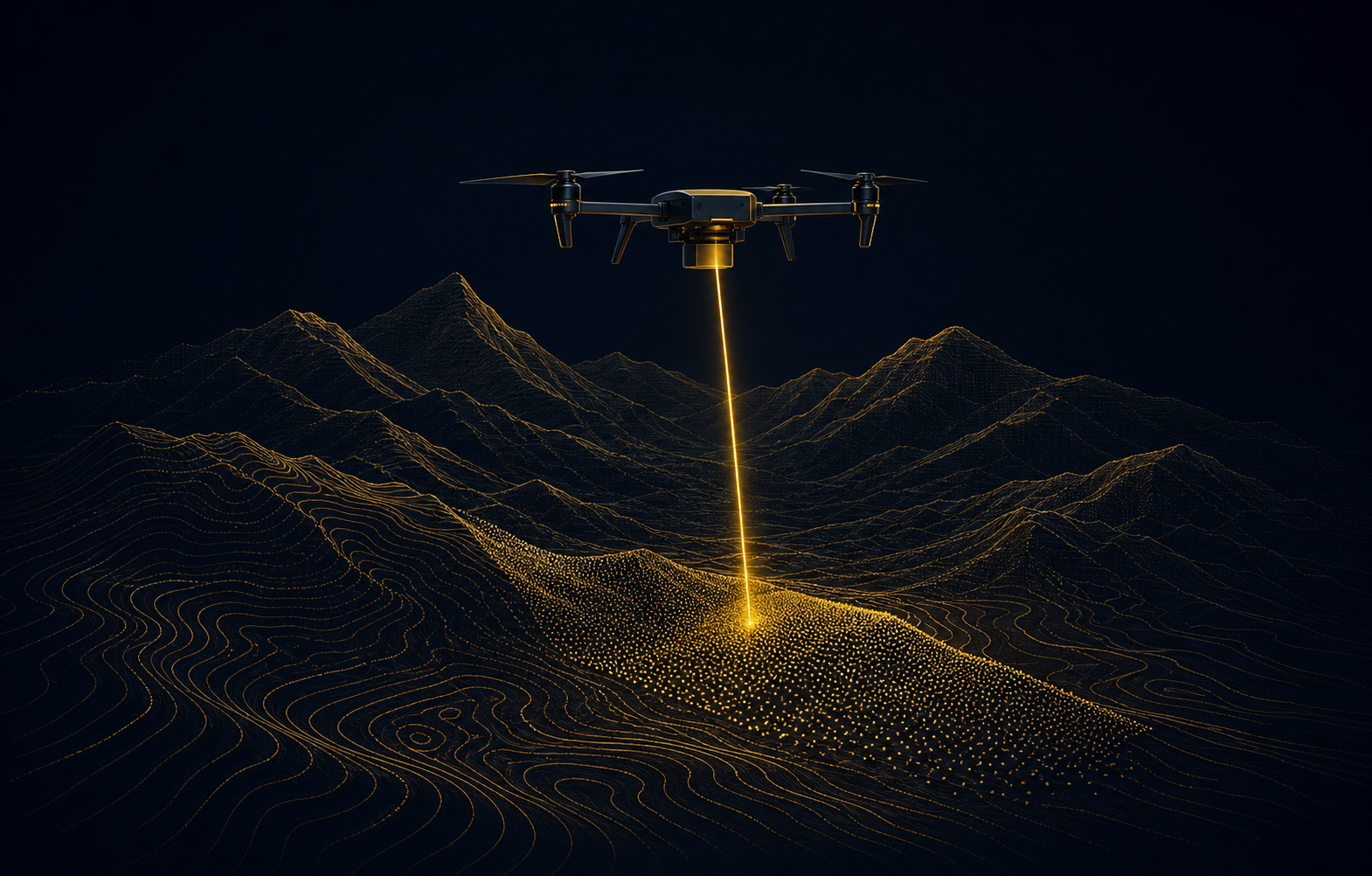
01 / رسم خرائط التضاريس
رسم خرائط التضاريس
دمج مصدر LiDAR المحمول جوًا للمسح الطبوغرافي وتوليد نماذج التضاريس.
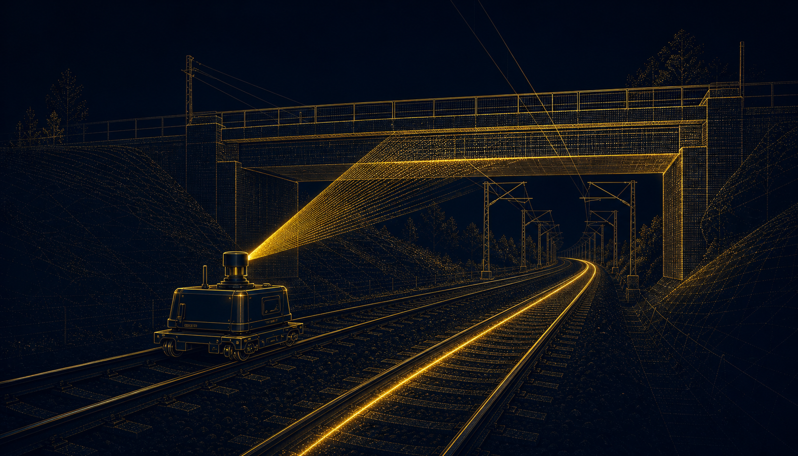
02 / البنية التحتية
ممرات السكك الحديدية والبنية التحتية
بنى المصدر النبضي للسكك الحديدية والطرق والقياسالتحتية الخطي.

03 / الصناعي
رسم الخرائط المتنقلة الصناعية
مصادر بصرية مدمجة للمسح المتنقل والقياس المكاني الصناعي.
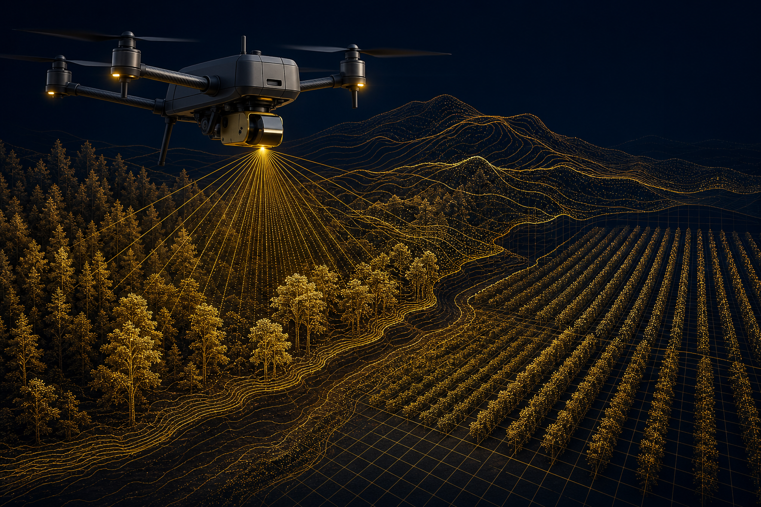
04 / الغابات والزراعة
الغابات والزراعة
سير عمل LiDAR المحمول جوًا لبنية المظلة وأشكال الأرض ورسم الخرائط الزراعية.
التكامل الميكانيكي والكهربائي
قم بحل واجهات الألياف والمشغل والطاقة والحرارية قبل تثبيت الهيكل المضيف.
استخدم الرسم الخاص بالنموذج وتعريف الموصل وحدود التشغيل كأساس للتصميم. تحقق من صحة النظام المضيف المُجمّع—بما في ذلك توجيه الألياف وإدارة الانحناء والضوضاء الكهربائية والنقل الحراري والوصول للصيانة—بدلاً من الليزر العاري بمعزل.
نظف، احمِ، حاذِ
طابق واجهة FC/APC أو FC/UPC مع بصريات المضيف واحمِ الأسطح الطرفية من التلوث.
توقيت النظام
أكد قطبية المشغل والتأخير والارتعاش والتأريض مع وثائق النموذج المختار.
إمداد 9–13 فولت
تحقق من بدء التشغيل والسعة الحالية والتموج وانخفاض الكابل—وليس الجهد فقط.
بناء مسار الحرارة
وفر تلامسًا متحكمًا مع الهيكل واختبر درجة الحرارة عند نقطة التشغيل المثبتة الفعلية.
الاختبار ومراقبة الجودة
تركز فحوصات مستوى المصدر على النبضة والتوصيل البصري والموثوقية ذات الصلة بالتكامل.
يتم تعريف خطة القبول التفصيلية والتأهيل البيئي للتكوين المحدد. اطلب السجل ذي الصلة ونطاق الاختبار عند التخطيط للعينات أو التسليم بالجملة.
الطول الموجي
تحقق من مخرجات المصدر مقابل مواصفات النموذج المختار 1535 نانومتر أو 1550 نانومتر.
مخرجات النبضة
تحقق من قدرة النبضة ومتوسط الإخراج عند نقطة التشغيل المحددة.
سلوك التوقيت
تحقق من عرض النبضة وعلاقة المشغل وسلوك التكرار حسب الاقتضاء.
توصيل الألياف
افحص حالة الموصل البصري واستقرار الإخراج عند واجهة الألياف.
الفحص البيئي
يتم تعريف نطاق درجة الحرارة والاهتزاز والشيخوخة بواسطة خطة التأهيل للمشروع.
تسليم قابل للتتبع
يمكن أن يرافق الشحنة تحديد النموذج والتتبع التسلسلي ومعلومات الفحص الصادر.
السلامة والامتثال: ليزر الألياف النبضي هو مصدر OEM. الجهاز المكتمل مسؤول عن التصنيف النهائي لسلامة الليزر وأي موافقات قابلة للتطبيق في تكوينه البصري والتشغيلي النهائي.
الأسئلة الشائعة قبل البيع
وضح مدخلات النظام قبل طلب العينات.
هذه الأسئلة تجعل النقاش الفني أكثر إنتاجية وتسمح لنا بالتوصية بتكوين المصدر الصحيح ووثائق التكامل ومسار التحقق.
كيف أختار بين 1535 نانومتر و1550 نانومتر؟
ابدأ بحساسية المستقبل وبصريات الإرسال واختيار الكاشف والمسار الجوي وتقييم السلامة النهائي وبنية النظام الحالية. يجب اختيار الطول الموجي للنظام الكامل بدلاً من رقم القدرة القصوى وحدها.
ماذا تخبرني القدرة القصوى؟
It indicates the instantaneous optical power during the pulse. It must be read together with pulse width, repetition rate, average power, fiber delivery and the receiver’s signal margin. It is not a stand-alone measure of final system range or point-cloud quality.
Can I select any pulse-width and repetition-rate combination?
No. The values on this page identify published configuration settings. Available combinations, triggering behavior and performance limits are confirmed in the selected model’s technical specification.
Which fiber output should I use?
The 1535 nm 1.2 kW model lists FC/APC + FC/UPC; the two 1550 nm models list FC/APC. Connector, fiber routing, bend radius, cleanliness and downstream optical compatibility should all be verified during design-in.
What host information is needed for a sample recommendation?
Provide target application, wavelength preference, desired pulse and repetition regime, host optical layout, receiver type, supply rail, available thermal path, enclosure volume, operating temperature and planned evaluation date.
Can Lumexis support customised integration?
We can evaluate OEM requests around optical output, mechanical interface, electrical connection, trigger configuration and programme documentation. Feasibility depends on the requested performance, validation scope and production requirement.
Start an OEM source review
Select the pulsed source with the complete LiDAR system in view.
Send your required wavelength, pulse regime, receiver and optical layout, mechanical envelope, electrical supply and thermal conditions. We will identify the relevant models and engineering documents for evaluation.