









An RFQ arrives asking for a “single mode 976 nm fiber coupled diode, 30 W.” That specification cannot be built. Not by us, not by anyone — it asks for roughly a thousand times more power than a single-mode emitter can produce.
The engineer who wrote it was not careless. They needed narrow linewidth for a spectroscopy front end and 30 W for a pump stage, and the word “single mode” quietly means two different things depending on which of those you are thinking about.
That ambiguity is the single most expensive misunderstanding in diode laser specification. This guide separates the two meanings, then works through the real selection axis: beam quality against deliverable power, and what each choice locks in downstream.
Table of Contents
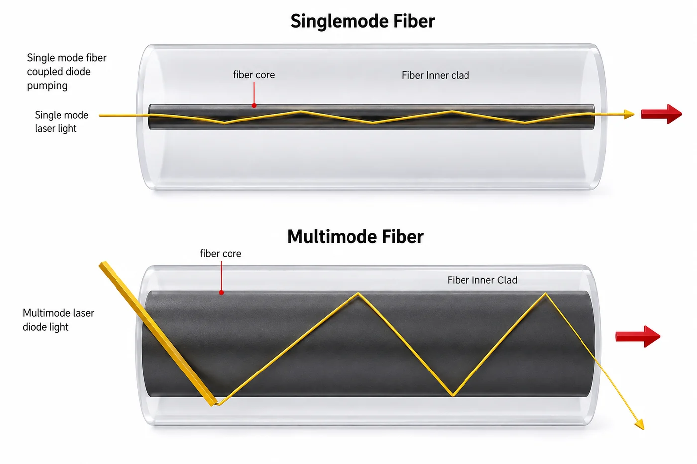
Single-mode fiber confines light to a core of a few micrometres; multimode fiber uses a far larger core that accepts many propagation paths.
First: which “single mode” do you mean?
The term is overloaded, and the two meanings are independent. A diode can be either, both, or neither.
Single transverse mode is a spatial property. The emitter is narrow enough — typically a waveguide below about 3–5 µm — that only one spatial mode propagates. The output is a clean, near-Gaussian TEM₀₀ beam that can be focused to a diffraction-limited spot and launched into single-mode fiber. This is what “single mode” means when someone is talking about beam quality, spot size, or fiber type.
Single longitudinal mode is a spectral property. The laser oscillates on one cavity mode, giving one narrow optical frequency rather than a comb of lines. This is what “single mode” means when someone is talking about linewidth, coherence length, or interferometry.
A plain Fabry-Pérot diode illustrates why the distinction matters. It can be perfectly single-transverse-mode — beautiful beam, couples straight into SMF — while emitting a dozen longitudinal lines spread over a nanometre or more, and hopping between them as temperature or current shifts. Great beam, useless coherence.
Getting single longitudinal mode requires a wavelength-selective element inside the cavity. That is what DFB and DBR structures do.
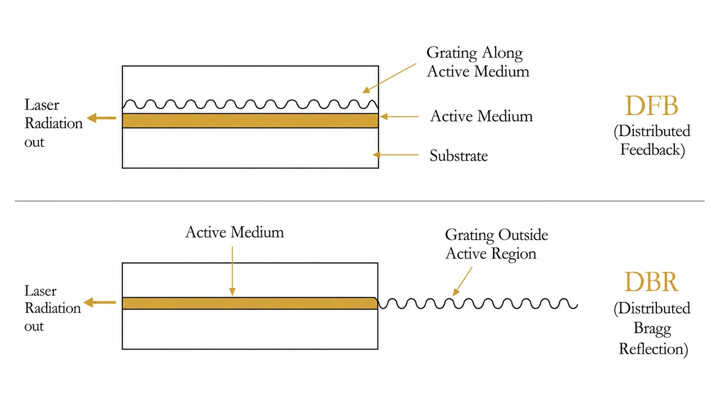
DFB (distributed feedback) writes a Bragg grating along the active medium itself. Selection happens continuously through the gain region, giving very narrow linewidth and a wavelength that moves only slightly with temperature — roughly 0.06 nm/°C rather than the ~0.3 nm/°C of a plain FP diode.
DBR (distributed Bragg reflector) places the grating outside the active region, acting as a wavelength-selective mirror. Similar effect, different fabrication trade-offs.
So when a specification says “single mode,” ask which axis it means. If the answer is “both,” you are looking at a DFB in a single-mode package — and you are firmly in the milliwatt-to-watt regime, no matter what the power line of the RFQ says.
Why power and beam quality cannot both be maximized
This is not a manufacturing limitation that better engineering will eventually remove. It is a conservation law.
A single transverse mode requires a narrow waveguide. A narrow waveguide has a small emitting aperture. A small aperture can only carry so much optical power before the facet damages. That chain caps single-mode output at roughly 1 W, with most devices well below it.
To get more power you widen the emitter. A broad-area diode with a 100 µm-wide stripe carries far more power — but it now supports many transverse modes across that width, and the beam degrades accordingly.
The quantity that tracks this is beam parameter product (BPP), or equivalently M²:
| Single mode | Multimode | |
|---|---|---|
| M² | ≈1.0–1.3 | 5 to 100+ |
| Typical power | mW to ~1 W | Watts to kilowatts |
| Emitter width | Below ~3–5 µm | 50–200 µm and wider |
| Far field | Smooth, bell-shaped | Structured, often “rabbit-ear” double-peaked |
| Fiber core | 6–9 µm | 105, 200, 400 µm and larger |
| Coherence length | Millimetres to metres | Micrometres to millimetres |
| Spot achievable | Diffraction-limited, <5 µm | Tens of µm and up |
| Cost structure | High per device | Low per watt |
Between those extremes sit quasi-single-mode devices with M² around 2–4 — broad-area emitters running in a small number of modes. They are genuinely useful when your spot budget has some slack and you need more than a watt, and they are worth asking about rather than jumping straight to a full multimode part.
The rule that follows from all this: brightness cannot be recovered downstream. Optics reshape a beam; they cannot reduce the product of size and divergence. You can turn a good beam into a bad one at any time. You can never go the other way. Every decision after the emitter inherits the beam quality the emitter produced.
That is why the RFQ at the top of this article is unbuildable, and why “we’ll fix it with better coupling optics” never works.
How multimode modules actually reach high power
If a single broad-area emitter tops out at tens of watts, how does a 300 W fiber-coupled module exist? By combining many emitters and accepting the beam quality penalty deliberately.
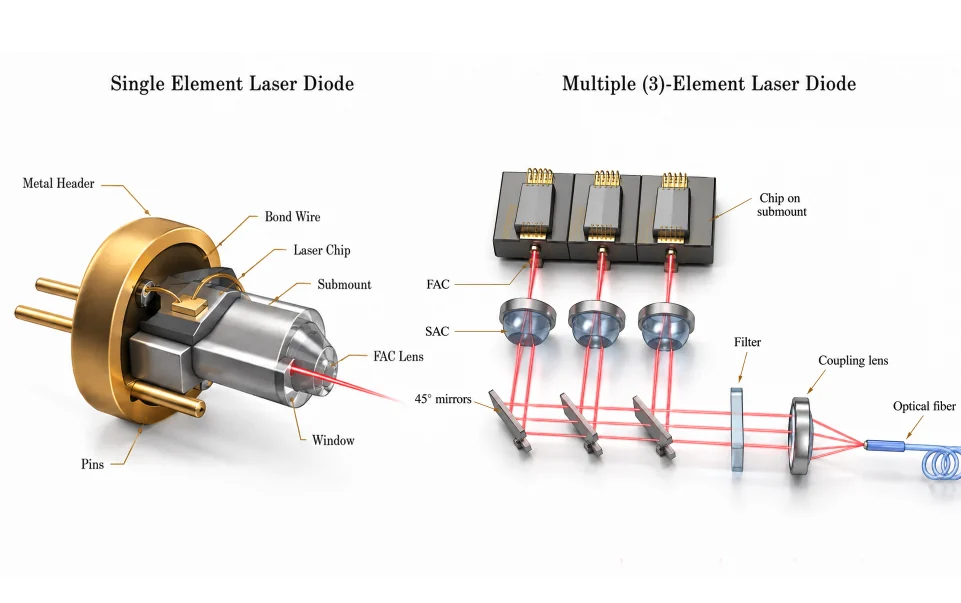
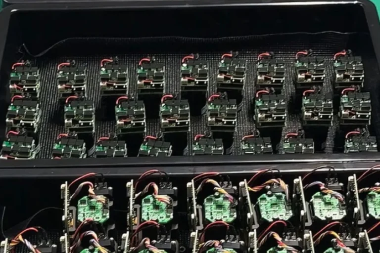
The optical chain in a multi-emitter module runs roughly like this. Each chip sits on its own submount. A fast-axis collimator (FAC) tames the highly divergent fast axis first, because that axis diverges fastest and gets ugliest if you wait. A slow-axis collimator (SAC) handles the other axis. 45° folding mirrors then stack the individual collimated beams into a compact bundle — this is spatial beam combining, and it is where most of the module’s brightness is decided. An optional filter and a coupling lens focus the stack into the delivery fiber.
Two more combining techniques usually ride along: polarization multiplexing, which overlaps two beams of orthogonal polarization at a beamsplitter and doubles power at no étendue cost, and wavelength multiplexing, which combines slightly different wavelengths dichroically. Both are ways of adding power without adding beam parameter product, which is exactly the currency that matters.
Three practical consequences fall out of this construction, and none of them appear on a datasheet’s front page.
Alignment is the product. A multi-emitter module’s coupled power is the result of dozens of individually aligned optical elements. That is why coupled power at the connector — not chip power, not pre-coupling power — is the only number worth comparing, and why alignment stability over temperature and vibration deserves a question in your RFQ.
Failure is graceful, but only in this architecture. Lose one emitter in a 20-emitter module and you lose roughly 5% of the power; the system keeps running. On a monolithic bar, where many emitters share one chip, a single emitter failure can propagate. For unattended or field-deployed systems this reliability difference often outweighs a few percent of efficiency.
More emitters means lower brightness, always. Every beam you stack adds to the total étendue. A 300 W module and a 15 W single-emitter module can share a 105 µm fiber spec and still behave very differently in your system, because the 300 W part will need a higher NA or a bigger core to get there.
Fiber: the choice that locks everything else
The delivery fiber is where the emitter’s beam quality becomes a hard system constraint.
Single-mode fiber has a core of roughly 6 µm at 1 µm wavelength, 9 µm at 1.5 µm. Only one spatial mode propagates, so whatever goes in comes out as a clean mode — the fiber acts as a spatial filter. Coupling into it demands a genuinely single-mode source and precise alignment with an aspheric lens; a multimode source simply cannot be launched into it with useful efficiency.
Multimode fiber uses cores of 105, 200, 400 µm and larger. Many paths propagate, which is what allows it to accept a high-divergence, poor-M² source. The trade is that spatial mode information is lost and modal dispersion sets in over distance — irrelevant for a metre of pump delivery, significant for long links.
Two numbers govern whether the launch works at all: core diameter and numerical aperture. NA sets the angular acceptance. Mismatch it and coupling efficiency falls fast — an NA shortfall of 0.05 can cost around 20% of the coupled power, and that lost light becomes heat right at the launch.
This is why a power figure without core and NA attached is not a specification. “50 W” in a 105 µm / 0.22 NA fiber and “50 W” in a 400 µm / 0.22 NA fiber are different products with different downstream options, and only one of them will feed a small inner cladding.
Wavelength stabilization: an axis of its own
Beam quality and spectral behaviour are separate choices, and this is where many designs quietly go wrong.
A plain FP diode drifts roughly 0.3 nm per °C of junction temperature and also shifts with drive current. If your system depends on the emission staying inside a narrow absorption band or a narrow receiver filter, that drift is a real problem — regardless of whether the diode is single or multimode spatially.
For multimode pump diodes, the standard fix is a fiber Bragg grating written into the delivery pigtail.
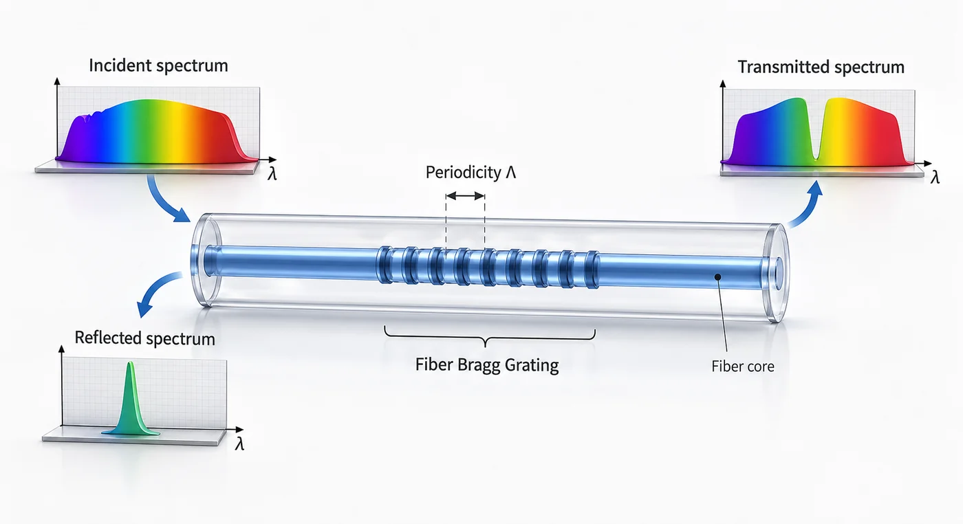
The grating reflects a narrow band determined by its periodicity back into the diode, forcing it to lase there. Emission typically narrows below 0.5 nm and becomes largely independent of temperature and current. A volume Bragg grating achieves the same at the module level with a bulk element rather than in the fiber.
Two details worth knowing before specifying a locked device. The grating wavelength must sit close to the chip’s natural peak — within roughly ±5 nm — or locking becomes unreliable across the operating range. And locking is not instantaneous: light must make a round trip to the grating, so in pulsed or fast-modulated operation the first part of each pulse can emit unlocked and spectrally broad.
Choosing: work backwards from the constraint
Pick whichever of these binds hardest in your system. It usually decides the answer on its own.
Spot size. Need below about 5 µm, or a diffraction-limited focus? Single mode, and the power ceiling is what it is. Working at tens of micrometres or larger? Multimode is available and far cheaper per watt.
Coherence. Interferometry, OCT, holography, coherent LiDAR, heterodyne detection, or narrow-line spectroscopy all need long coherence — which means single longitudinal mode, so DFB or DBR, and therefore low power. If coherence does not appear in your requirements at all, do not pay for it.
Power. Above a few watts the question is settled: multimode. Fiber laser and DPSS pumping, direct-diode material processing, and illumination all live here, and all of them tolerate poor beam quality by design — cladding pumping exists precisely to convert low-brightness diode light into a high-brightness fiber laser output.
Fiber already fixed by the rest of the system. If the fiber is given, the emitter is largely given too. Work from the core and NA back to the source, not the other way round.
Thermal budget. Single-mode devices often run on passive heatsinking. High-power multimode parts need a specified case temperature with conduction cooling, and water cooling above a few hundred watts. If wavelength stability matters, add a TEC or a stabilized device — and account for both in the power budget.
Leave roughly 30% headroom on the power requirement. Coupling losses, connector losses, and end-of-life derating all consume margin that looked comfortable on paper.
What separates two modules with the same datasheet
Coupled power at the connector is produced by alignment, and it holds its value only if the alignment and the emitter hold theirs.
Our own flow for fiber-coupled diode sources runs incoming inspection, chip test, die bonding and chip-on-submount assembly, automated fiber coupling and alignment, hermetic sealing by parallel seam welding, then burn-in and high/low temperature cycling before final test. Burn-in exists to find early-life failures before shipment. Temperature cycling exists because a module that meets spec at 25 °C and drifts at −20 °C was never really in spec — it was measured once, in the easy condition.
Worth asking any supplier: is coupled power specified at the connector or before it; is the centre wavelength given with a tolerance and a reference case temperature; was every unit burn-in screened or a sample; is the package hermetic; and can you see wavelength and power data at the temperature extremes rather than at ambient. You can review the test and qualification equipment behind those answers, or browse available laser source modules when you are scoping a specific wavelength and power.
If fiber coupling itself is the part you want to understand more deeply — coupling efficiency, terminations, delivery-path specification — our guide to what a fiber coupled laser is covers that ground.
Common mistakes
Writing “single mode” without saying which kind. Specify transverse, longitudinal, or both. This one ambiguity produces more unbuildable RFQs than any other.
Asking for single-mode beam quality at multi-watt power. Physically unavailable. If both are genuinely required, the answer is a fiber laser or amplifier stage, not a diode.
Comparing modules on watts alone. Without core diameter and NA, the number says nothing about whether it fits your system.
Assuming optics can clean up a multimode beam. Étendue only grows. Spatial filtering can improve the beam, but only by throwing away the power that made it multimode.
Ignoring wavelength drift because the diode is “stabilized.” Check the linewidth, the locking wavelength tolerance, and whether locking is established fast enough for your pulse format.
Qualifying at ambient only. Wavelength, coupled power, and threshold all move with temperature.
Frequently asked questions
What is the difference between a single mode and multimode laser diode?
A single mode diode emits one transverse spatial mode with M² near 1, giving a clean focusable beam but limited to roughly 1 W. A multimode diode uses a wide emitter supporting many spatial modes, with M² from 5 to over 100, reaching watts to kilowatts. Beam quality and power trade directly.
Can a laser diode be single mode and high power?
Not at the same time. Single transverse mode requires a narrow emitter, and a narrow emitter caps power at around 1 W before facet damage. High power requires a wide emitter, which supports many modes. Combining both needs a fiber laser or amplifier downstream of a single-mode seed.
What is the difference between single transverse mode and single longitudinal mode?
Transverse mode is spatial — it describes the beam shape and whether it can focus to a diffraction-limited spot. Longitudinal mode is spectral — it describes how many optical frequencies oscillate. A Fabry-Pérot diode can be single transverse mode while emitting many longitudinal lines.
Which fiber core size do I need?
Single-mode sources go into 6–9 µm single-mode fiber. Multimode sources use 105, 200, or 400 µm cores depending on power and the module’s brightness. Always match numerical aperture as well — an NA shortfall of 0.05 can cost about 20% of coupled power as heat at the launch.
Why do fiber laser pumps use multimode diodes?
Because cladding pumping does not need beam quality. Pump light is launched into a large multimode inner cladding and absorbed gradually along the fiber, so cheap high-power multimode diodes can drive a single-mode fiber laser output. Beam quality is created by the fiber, not the pump.
What does M² tell me that power does not?
M² describes how far the beam is from diffraction-limited, which determines the smallest spot it can be focused to and whether it can enter a given fiber. Two diodes with identical power and very different M² are not interchangeable in any system with a spot-size or coupling constraint.
Specifying the source alongside the delivery path
Decide the binding constraint first — spot size, coherence, power, or an already-fixed fiber — then let it choose the mode type. Trying to optimize beam quality and power at once produces a specification nobody can quote.
Send us your spot or coupling requirement, power target, wavelength, and temperature envelope, and our engineers will work through the options with you — including whether a quasi-single-mode part closes the gap, and what the coupled-power and wavelength data needs to show across your operating range.
References
- Optics & Laser Technology — Coupling multi-beam laser diode to multimode fiber by wedge prism combiner
- Results in Physics — Design of a 36-W fiber-coupled green laser diode by Zemax
- SPIE — Basic Concepts: modes and beam quality