



Llega una RFQ solicitando un “diodo monomodo de 976 nm acoplado a fibra, 30 W.” Esa especificación no se puede construir. Ni por nosotros, ni por nadie: pide aproximadamente mil veces más potencia de la que un emisor monomodo puede producir.
El ingeniero que la redactó no fue descuidado. Necesitaba un ancho de línea estrecho para un front-end de espectroscopía y 30 W para una etapa de bombeo, y la palabra “monomodo” significa silenciosamente dos cosas diferentes según cuál de esas estés considerando.
Esa ambigüedad es el malentendido más costoso en la especificación de diodos láser. Esta guía separa los dos significados y luego recorre el eje de selección real: calidad del haz frente a potencia entregable, y qué bloquea cada elección aguas abajo.
Tabla de Contenidos
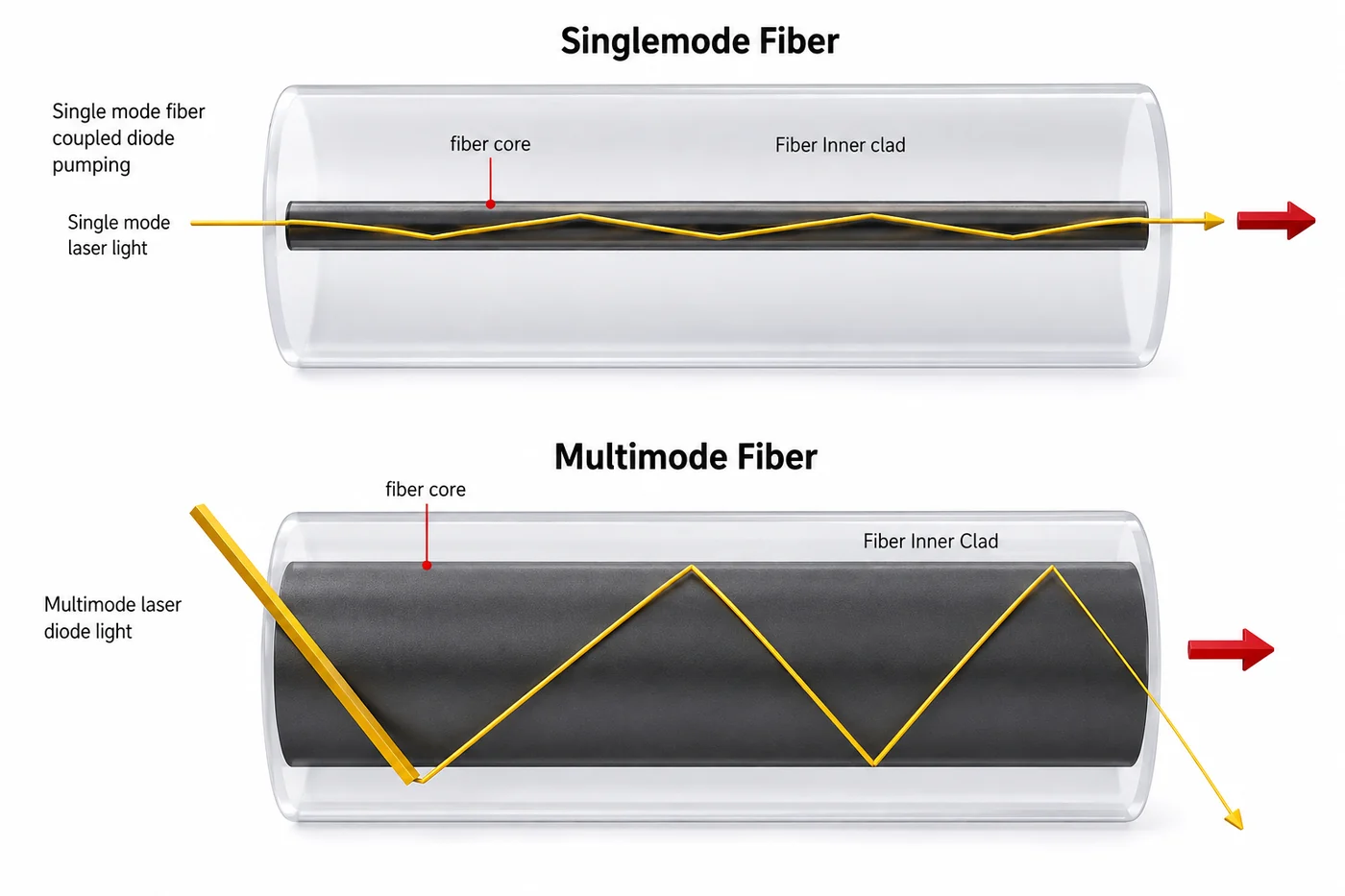
La fibra monomodo confina la luz a un núcleo de unos pocos micrómetros; la fibra multimodo usa un núcleo mucho más grande que acepta muchas rutas de propagación.
Primero: ¿qué “monomodo” quieres decir?
El término está sobrecargado, y los dos significados son independientes. Un diodo puede ser cualquiera, ambos o ninguno.
Modo transversal único es una propiedad espacial. El emisor es lo suficientemente estrecho — típicamente una guía de ondas por debajo de unos 3–5 µm — que solo se propaga un modo espacial. La salida es un haz limpio, casi gaussiano TEM₀₀ que puede enfocarse a un punto limitado por difracción y lanzarse en fibra monomodo. Esto es lo que “monomodo” significa cuando alguien habla de calidad del haz, tamaño del punto o tipo de fibra.
Modo longitudinal único es una propiedad espectral. El láser oscila en un modo de cavidad único, dando una frecuencia óptica estrecha en lugar de un peine de líneas. Esto es lo que “monomodo” significa cuando alguien habla de ancho de línea, longitud de coherencia o interferometría.
Un diodo Fabry-Pérot simple ilustra por qué la distinción importa. Puede ser perfectamente de modotransversalúnico — haz hermoso, se acopla directamente en SMF — mientras emite una docena de líneas longitudinales distribuidas en un nanómetro o más, y saltando entre ellas a medida que la temperatura o la corriente cambian. Gran haz, coherencia inútil.
Obtener un modo longitudinal único requiere un elemento selectivo de longitud de onda dentro de la cavidad. Eso es lo que hacen las estructuras DFB y DBR.
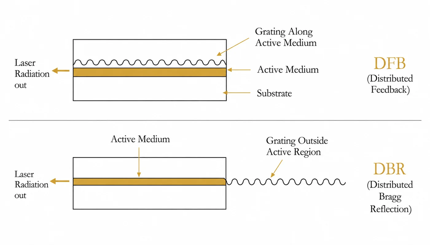
DFB (retroalimentación distribuida) escribe una rejilla de Bragg a lo largo del medio activo mismo. La selección ocurre continuamente a través de la región de ganancia, dando un ancho de línea muy estrecho y una longitud de onda que se mueve solo ligeramente con la temperatura — aproximadamente 0.06 nm/°C en lugar de los ~0.3 nm/°C de un diodo FP simple.
DBR (reflector de Bragg distribuido) coloca la rejilla fuera de la región activa, actuando como un espejo selectivo de longitud de onda. Efecto similar, diferentes compensaciones de fabricación.
Entonces, cuando una especificación dice “monomodo”, pregunta qué eje significa. Si la respuesta es “ambos”, estás mirando un DFB en un paquete monomodo — y estás firmemente en el régimen de milivatios a vatios, sin importar lo que diga la línea de potencia de la RFQ.
Por qué la potencia y la calidad del haz no pueden maximizarse ambas
Esto no es una limitación de fabricación que una mejor ingeniería eventualmente eliminará. Es una ley de conservación.
Un modo transversal único requiere una guía de ondas estrecha. Una guía de ondas estrecha tiene una apertura de emisión pequeña. Una apertura pequeña solo puede llevar tanta potencia óptica antes de que la faceta se dañe. Esa cadena limita la salida monomodo a aproximadamente 1 W, con la mayoría de los dispositivos muy por debajo de eso.
Para obtener más potencia, ensanchas el emisor. Un diodo de área amplia con una franja de 100 µm de ancho lleva mucho más potencia — pero ahora soporta muchos modos transversales a través de ese ancho, y el haz se degrada en consecuencia.
La cantidad que rastrea esto es el producto de parámetros de haz (BPP), o equivalentemente M²:
| Monomodo | Multimodo | |
|---|---|---|
| M² | ≈1.0–1.3 | 5 a 100+ |
| Potencia típica | mW a ~1 W | Vatios a kilovatios |
| Ancho del emisor | Por debajo de ~3–5 µm | 50–200 µm y más ancho |
| Campo lejano | Suave, en forma de campana | Estructurado, a menudo con “orejas de conejo” de doble pico |
| Núcleo de fibra | 6–9 µm | 105, 200, 400 µm y más grande |
| Longitud de coherencia | Milímetros a metros | Micrómetros a milímetros |
| Punto alcanzable | Diffraction-limited, <5 µm | Tens of µm and up |
| Cost structure | High per device | Low per watt |
Between those extremes sit quasi-single-mode devices with M² around 2–4 — broad-area emitters running in a small number of modes. They are genuinely useful when your spot budget has some slack and you need more than a watt, and they are worth asking about rather than jumping straight to a full multimode part.
The rule that follows from all this: brightness cannot be recovered downstream. Optics reshape a beam; they cannot reduce the product of size and divergence. You can turn a good beam into a bad one at any time. You can never go the other way. Every decision after the emitter inherits the beam quality the emitter produced.
That is why the RFQ at the top of this article is unbuildable, and why “we’ll fix it with better coupling optics” never works.
Cómo los módulos multimodo realmente alcanzan alta potencia
If a single broad-area emitter tops out at tens of watts, how does a 300 W fiber-coupled module exist? By combining many emitters and accepting the beam quality penalty deliberately.
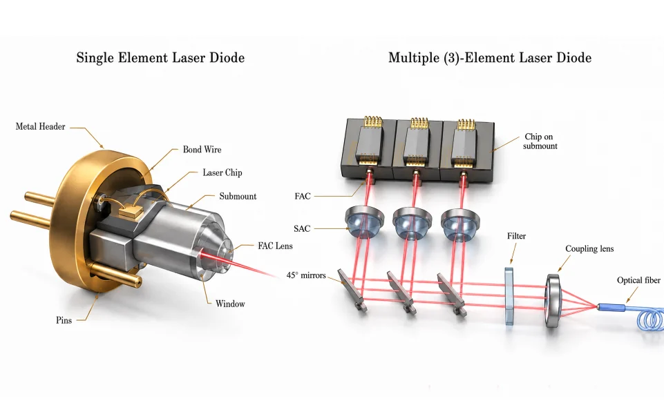
The optical chain in a multi-emitter module runs roughly like this. Each chip sits on its own submount. A fast-axis collimator (FAC) tames the highly divergent fast axis first, because that axis diverges fastest and gets ugliest if you wait. A slow-axis collimator (SAC) handles the other axis. 45° folding mirrors then stack the individual collimated beams into a compact bundle — this is spatial beam combining, and it is where most of the module’s brightness is decided. An optional filter and a coupling lens focus the stack into the delivery fiber.
Two more combining techniques usually ride along: polarization multiplexing, which overlaps two beams of orthogonal polarization at a beamsplitter and doubles power at no étendue cost, and wavelength multiplexing, which combines slightly different wavelengths dichroically. Both are ways of adding power without adding beam parameter product, which is exactly the currency that matters.
Three practical consequences fall out of this construction, and none of them appear on a datasheet’s front page.
Alignment is the product. A multi-emitter module’s coupled power is the result of dozens of individually aligned optical elements. That is why coupled power at the connector — not chip power, not pre-coupling power — is the only number worth comparing, and why alignment stability over temperature and vibration deserves a question in your RFQ.
Failure is graceful, but only in this architecture. Lose one emitter in a 20-emitter module and you lose roughly 5% of the power; the system keeps running. On a monolithic bar, where many emitters share one chip, a single emitter failure can propagate. For unattended or field-deployed systems this reliability difference often outweighs a few percent of efficiency.
More emitters means lower brightness, always. Every beam you stack adds to the total étendue. A 300 W module and a 15 W single-emitter module can share a 105 µm fiber spec and still behave very differently in your system, because the 300 W part will need a higher NA or a bigger core to get there.
Fibra: la elección que lo asegura todo
The delivery fiber is where the emitter’s beam quality becomes a hard system constraint.
Single-mode fiber has a core of roughly 6 µm at 1 µm wavelength, 9 µm at 1.5 µm. Only one spatial mode propagates, so whatever goes in comes out as a clean mode — the fiber acts as a spatial filter. Coupling into it demands a genuinely single-mode source and precise alignment with an aspheric lens; a multimode source simply cannot be launched into it with useful efficiency.
Fibra multimodo uses cores of 105, 200, 400 µm and larger. Many paths propagate, which is what allows it to accept a high-divergence, poor-M² source. The trade is that spatial mode information is lost and modal dispersion sets in over distance — irrelevant for a metre of pump delivery, significant for long links.
Two numbers govern whether the launch works at all: core diameter and numerical aperture. NA sets the angular acceptance. Mismatch it and coupling efficiency falls fast — an NA shortfall of 0.05 can cost around 20% of the coupled power, and that lost light becomes heat right at the launch.
This is why a power figure without core and NA attached is not a specification. “50 W” in a 105 µm / 0.22 NA fiber and “50 W” in a 400 µm / 0.22 NA fiber are different products with different downstream options, and only one of them will feed a small inner cladding.
Estabilización de longitud de onda: un eje propio
Beam quality and spectral behaviour are separate choices, and this is where many designs quietly go wrong.
A plain FP diode drifts roughly 0.3 nm per °C of junction temperature and also shifts with drive current. If your system depends on the emission staying inside a narrow absorption band or a narrow receiver filter, that drift is a real problem — regardless of whether the diode is single or multimode spatially.
For multimode pump diodes, the standard fix is a fiber Bragg grating written into the delivery pigtail.
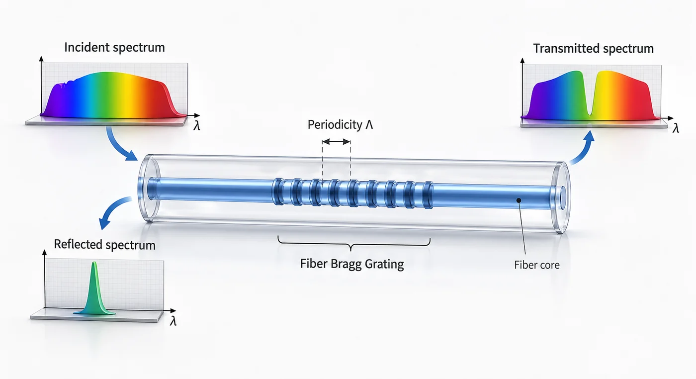
The grating reflects a narrow band determined by its periodicity back into the diode, forcing it to lase there. Emission typically narrows below 0.5 nm and becomes largely independent of temperature and current. A volume Bragg grating achieves the same at the module level with a bulk element rather than in the fiber.
Two details worth knowing before specifying a locked device. The grating wavelength must sit close to the chip’s natural peak — within roughly ±5 nm — or locking becomes unreliable across the operating range. And locking is not instantaneous: light must make a round trip to the grating, so in pulsed or fast-modulated operation the first part of each pulse can emit unlocked and spectrally broad.
Elegir: trabajar hacia atrás desde la restricción
Pick whichever of these binds hardest in your system. It usually decides the answer on its own.
Spot size. Need below about 5 µm, or a diffraction-limited focus? Single mode, and the power ceiling is what it is. Working at tens of micrometres or larger? Multimode is available and far cheaper per watt.
Coherence. Interferometry, OCT, holography, coherent LiDAR, heterodyne detection, or narrow-line spectroscopy all need long coherence — which means single longitudinal mode, so DFB or DBR, and therefore low power. If coherence does not appear in your requirements at all, do not pay for it.
Power. Above a few watts the question is settled: multimode. Fiber laser and DPSS pumping, direct-diode material processing, and illumination all live here, and all of them tolerate poor beam quality by design — cladding pumping exists precisely to convert low-brightness diode light into a high-brightness fiber laser output.
Fiber already fixed by the rest of the system. If the fiber is given, the emitter is largely given too. Work from the core and NA back to the source, not the other way round.
Thermal budget. Single-mode devices often run on passive heatsinking. High-power multimode parts need a specified case temperature with conduction cooling, and water cooling above a few hundred watts. If wavelength stability matters, add a TEC or a stabilized device — and account for both in the power budget.
Leave roughly 30% headroom on the power requirement. Coupling losses, connector losses, and end-of-life derating all consume margin that looked comfortable on paper.
¿Qué separa a dos módulos con la misma hoja de datos
Coupled power at the connector is produced by alignment, and it holds its value only if the alignment and the emitter hold theirs.
Nuestro propio flujo para fiber-coupled diode sources runs incoming inspection, chip test, die bonding and chip-on-submount assembly, automated fiber coupling and alignment, hermetic sealing by parallel seam welding, then burn-in and high/low temperature cycling before final test. Burn-in exists to find early-life failures before shipment. Temperature cycling exists because a module that meets spec at 25 °C and drifts at −20 °C was never really in spec — it was measured once, in the easy condition.
Worth asking any supplier: is coupled power specified at the connector or before it; is the centre wavelength given with a tolerance y a reference case temperature; was every unit burn-in screened or a sample; is the package hermetic; and can you see wavelength and power data at the temperature extremes rather than at ambient. You can review the test and qualification equipment behind those answers, or browse módulos de fuente láser disponibles when you are scoping a specific wavelength and power.
If fiber coupling itself is the part you want to understand more deeply — coupling efficiency, terminations, delivery-path specification — our guide to what a fiber coupled laser is covers that ground.
Errores comunes
Writing “single mode” without saying which kind. Specify transverse, longitudinal, or both. This one ambiguity produces more unbuildable RFQs than any other.
Asking for single-mode beam quality at multi-watt power. Physically unavailable. If both are genuinely required, the answer is a fiber laser or amplifier stage, not a diode.
Comparing modules on watts alone. Without core diameter and NA, the number says nothing about whether it fits your system.
Assuming optics can clean up a multimode beam. Étendue only grows. Spatial filtering can improve the beam, but only by throwing away the power that made it multimode.
Ignoring wavelength drift because the diode is “stabilized.” Check the linewidth, the locking wavelength tolerance, and whether locking is established fast enough for your pulse format.
Qualifying at ambient only. Wavelength, coupled power, and threshold all move with temperature.
Preguntas frecuentes
What is the difference between a single mode and multimode laser diode?
A single mode diode emits one transverse spatial mode with M² near 1, giving a clean focusable beam but limited to roughly 1 W. A multimode diode uses a wide emitter supporting many spatial modes, with M² from 5 to over 100, reaching watts to kilowatts. Beam quality and power trade directly.
Can a laser diode be single mode and high power?
Not at the same time. Single transverse mode requires a narrow emitter, and a narrow emitter caps power at around 1 W before facet damage. High power requires a wide emitter, which supports many modes. Combining both needs a fiber laser or amplifier downstream of a single-mode seed.
What is the difference between single transverse mode and single longitudinal mode?
Transverse mode is spatial — it describes the beam shape and whether it can focus to a diffraction-limited spot. Longitudinal mode is spectral — it describes how many optical frequencies oscillate. A Fabry-Pérot diode can be single transverse mode while emitting many longitudinal lines.
Which fiber core size do I need?
Single-mode sources go into 6–9 µm single-mode fiber. Multimode sources use 105, 200, or 400 µm cores depending on power and the module’s brightness. Always match numerical aperture as well — an NA shortfall of 0.05 can cost about 20% of coupled power as heat at the launch.
Why do fiber laser pumps use multimode diodes?
Because cladding pumping does not need beam quality. Pump light is launched into a large multimode inner cladding and absorbed gradually along the fiber, so cheap high-power multimode diodes can drive a single-mode fiber laser output. Beam quality is created by the fiber, not the pump.
What does M² tell me that power does not?
M² describes how far the beam is from diffraction-limited, which determines the smallest spot it can be focused to and whether it can enter a given fiber. Two diodes with identical power and very different M² are not interchangeable in any system with a spot-size or coupling constraint.
Especificando la fuente junto con la ruta de entrega
Decide the binding constraint first — spot size, coherence, power, or an already-fixed fiber — then let it choose the mode type. Trying to optimize beam quality and power at once produces a specification nobody can quote.
Send us your spot or coupling requirement, power target, wavelength, and temperature envelope, and our engineers will work through the options with you — including whether a quasi-single-mode part closes the gap, and what the coupled-power and wavelength data needs to show across your operating range.
Referencias
- Optics & Laser Technology — Coupling multi-beam laser diode to multimode fiber by wedge prism combiner
- Results in Physics — Design of a 36-W fiber-coupled green laser diode by Zemax
- SPIE — Basic Concepts: modes and beam quality