
تقنية مصدر الليزرللأنظمة الأصلية (OEM).
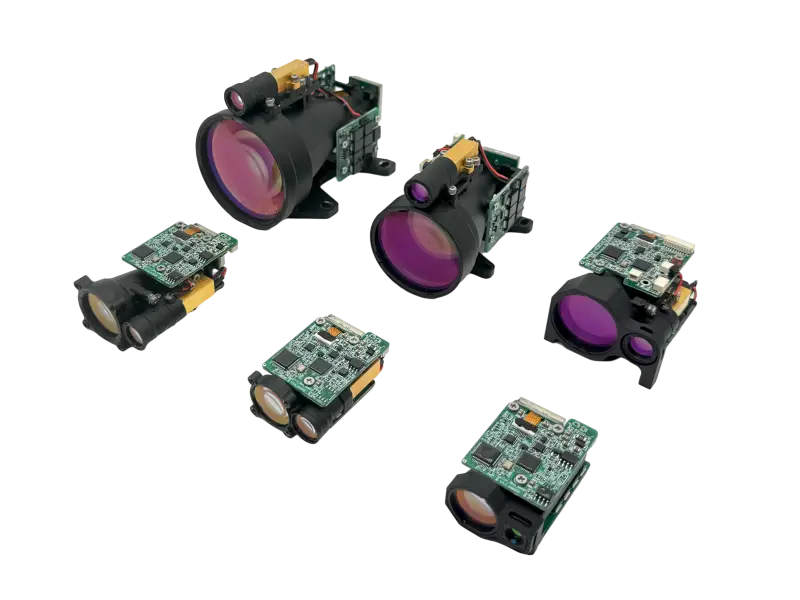
تطور لوميكسيس التقنيات البصرية والإلكترونية والحرارية والتصنيعية الكامنة وراء وحدات قياس مدى الليزر, ليزرات مقترنة بالألياف, مصادر ليزر ليدار (LiDAR) و مصادر ليزر زجاج الإربيوم. نحن نربط فيزياء المصدر بتكامل النظام والإنتاج القابل للتكرار.
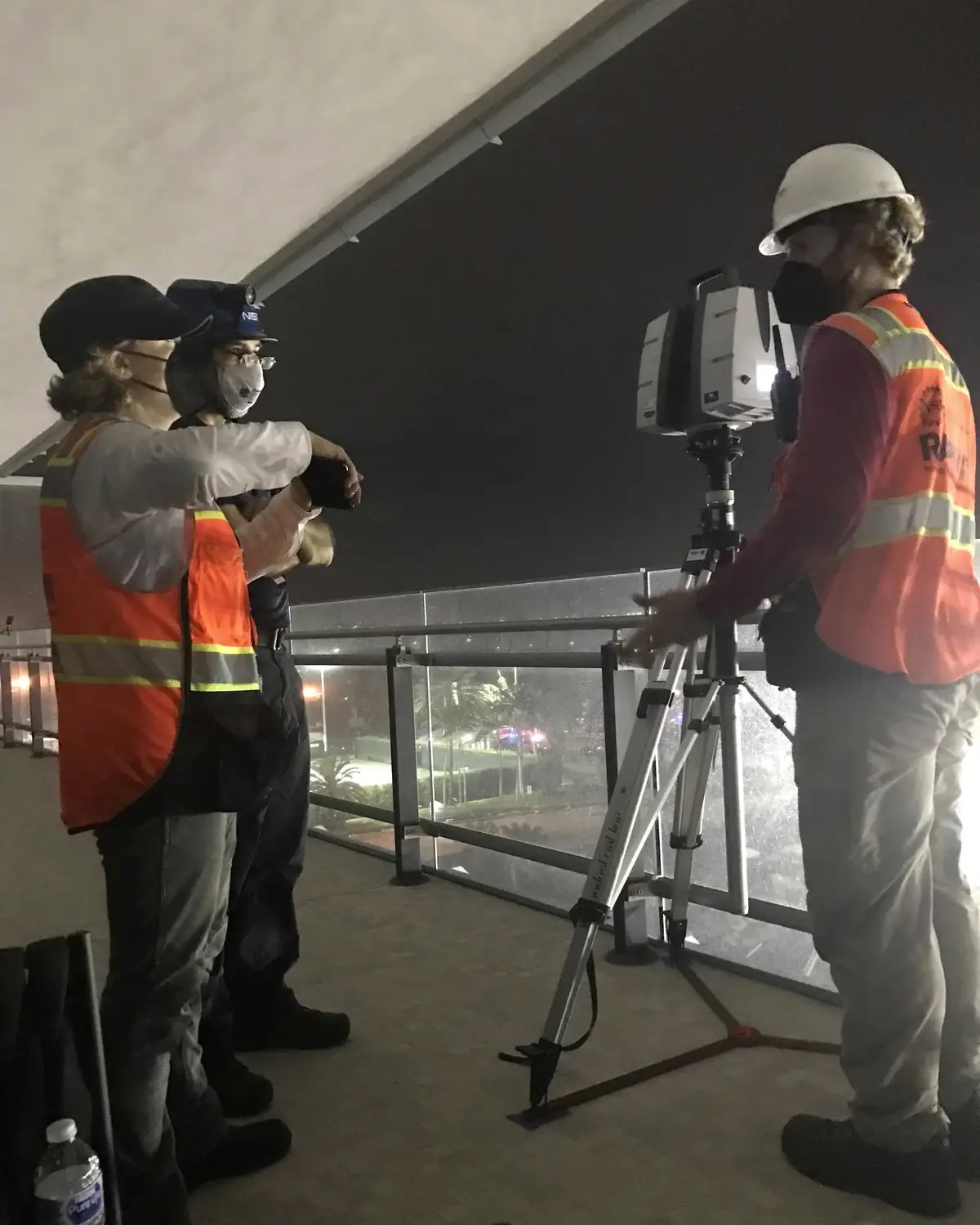 ليدار (LiDAR) · قياسات البنية التحتية
تقنية الليزر لأنظمة الفوتونيات الأصلية (OEM).
مصدر الليزر المفيد هو أكثر من مجرد طول موجي وقيمة طاقة. يجب أن تعمل سلوكيات نبضته، وتوصيل الحزمة، وسلسلة الاستقبال، والواجهات، والمسار الحراري، والتغليف معًا داخل نظام العميل.
تحديد المدى النبضي بزمن الطيران (TOF)
توقيت النبضة بالنانو ثانية، ومسارات الإرسال والاستقبال البصرية، واكتشاف الصدى، وحساب المدى.
اقرأ المبدأ ← 02 / توليدمصادر نبض زجاج الإربيوم
مصادر مدمجة تعمل بالضخ بالديود وحالة صلبة مصممة حول إخراج نانو ثانية بطول 1535 نانومتر.
استكشف المصدر ← 03 / توصيلالاقتران بالألياف والتحكم في الطول الموجي
تهيئة الحزمة، والمحاذاة النشطة، والتحكم في واجهة الألياف، وتثبيت طيفي اختياري.
اتبع المسار البصري ← 04 / تضخيممصادر ليزر نبضية بالألياف بطول 1.5 ميكرومتر
توليد نبضات قصيرة، ومعدل تكرار محكوم، وتوصيل بالألياف، وتكامل مرجع التوقيت.
شاهد البنية ← 05 / كشفإلكترونيات الاستقبال والتحكم
استقبال الصدى القائم على كاشف APD، وتضخيم منخفض الضوضاء، ومنطق التوقيت، والتواصل مع النظام المضيف.
تتبع الإشارة ← 06 / حفظالتغليف والتحقق
التصميم الحراري، والتجميع الدقيق، والإغلاق، والتقادم، وفحوصات الأداء البيئي.
شاهد العملية ←تقنية زمن الطيران النبضي لوحدات قياس مدى الليزر.
نبضة جهاز تحديد المدى بالليزر يقيس زمن رحلة الضوء ذهابًا وإيابًا. المعادلة بسيطة. إنتاج إجابة مفيدة عبر أهداف وبيئات متغيرة هو المهمة الهندسية الحقيقية.
المدى = سرعة الضوء × زمن الرحلة ذهابًا وإيابًا / 2يطلق المرسل نبضة ضوئية قصيرة. تجمع بصريات المستقبل جزءًا صغيرًا من الطاقة المنعكسة، ويحوّلها ثنائي ضوئي انهياري إلى إشارة كهربائية، وتقدّر إلكترونيات التوقيت عالية السرعة الفاصل بين الإرسال والعودة.
الطاقة وعرض النبضة
لطاقة نبضة معينة، تنتج النبضات الأقصر طاقة ذروة أعلى. التوازن المفيد يعتمد على الهدف، وعرض نطاق المستقبل، واستراتيجية التكرار، وقيود النظام.
التباعد وتغطية الهدف
يتحكم تباعد الحزمة في حجم البقعة مع المسافة. بقعة أصغر يمكن أن تحسن كثافة الطاقة على الأهداف المدمجة، لكن التسديد والمحاذاة وتفاوتات مجال الرؤية يجب أن تبقى عملية.
فتحة المستقبل والضوضاء
فتحة فعالة أكبر تجمع ضوء عودة أكثر. أداء الكشف لا يزال يعتمد على النقل البصري، وكسب الكاشف، وعرض النطاق التناظري، والخلفية المحيطة، واستراتيجية العتبة.
الغلاف الجوي وانعكاسية الهدف
الرؤية، والتوهين المعتمد على الطول الموجي، وحجم الهدف، وانعكاسية السطح، وزاوية السقوط كلها تؤثر على الصدى الذي يصل إلى المستقبل.
المدى الأقصى ليس خاصية لمكوّن واحد. إنه نتيجة لميزانية الوصلة الكاملة، بما في ذلك المصدر، والحزمة، والهدف، والغلاف الجوي، والمستقبل، وسلسلة معالجة الإشارات.
تقنية ليزر زجاج الإربيوم بطول موجة 1535 نانومتر.
يوفر الزجاج المشوب بالإربيوم وسط كسب صلب في المنطقة الطيفية 1.5 ميكرومتر. تدمج Lumexis مصدر الضخ، ووسط الكسب، والرنان، والتغليف، وظروف التشغيل كمنصة مصدر نبضي مدمجة واحدة.
ضخ ديود · زجاج إربيوم · خرج نانوثانيةالهدف الهندسي هو تحويل نبضة تشغيل كهربائية مضبوطة إلى طاقة ضوئية قابلة للتكرار مع إبقاء المصدر مدمجًا بما يكفي للدمج في وحدة جهاز تحديد المدى بالليزر أو أداة علمية.
مطابقة الضخ والكسب
يجب مطابقة مضخة أشباه الموصلات، وامتصاص زجاج الإربيوم، ونبضة التشغيل بحيث تُبنى الطاقة المخزنة بكفاءة دون حمل حراري غير ضروري.
تشكيل نبضة النانوثانية
تصميم الرنان والتحكم في الفقد يطلقان الطاقة المخزنة كنبضة قصيرة. طاقة النبضة، والعرض، ومعدل التكرار، وجودة الحزمة تُعامل كمعلمات مترابطة.
الاستقرار البصري الميكانيكي
العناصر والواجهات البصرية دون المليمترية تحتاج إلى وضع مضبوط، وربط، وإدارة تلوث للحفاظ على المحاذاة واتساق الخرج.
الحماية الكهربائية والتحكم في التشغيل
يجب التحكم في تيار ديود الليزر دون تجاوز أو اندفاع. التعامل الكهروستاتيكي، والأسطح البصرية النظيفة، ونقل الحرارة الموثوق تبقى جزءًا من تصميم المصدر.
الطول الموجي، وطاقة النبضة، وعرض النبضة، ومعدل التكرار، وجودة الحزمة، والتباعد، والتشغيل الكهربائي، والغلاف الميكانيكي كلها متوازنة مقابل متطلبات النظام النهائي.
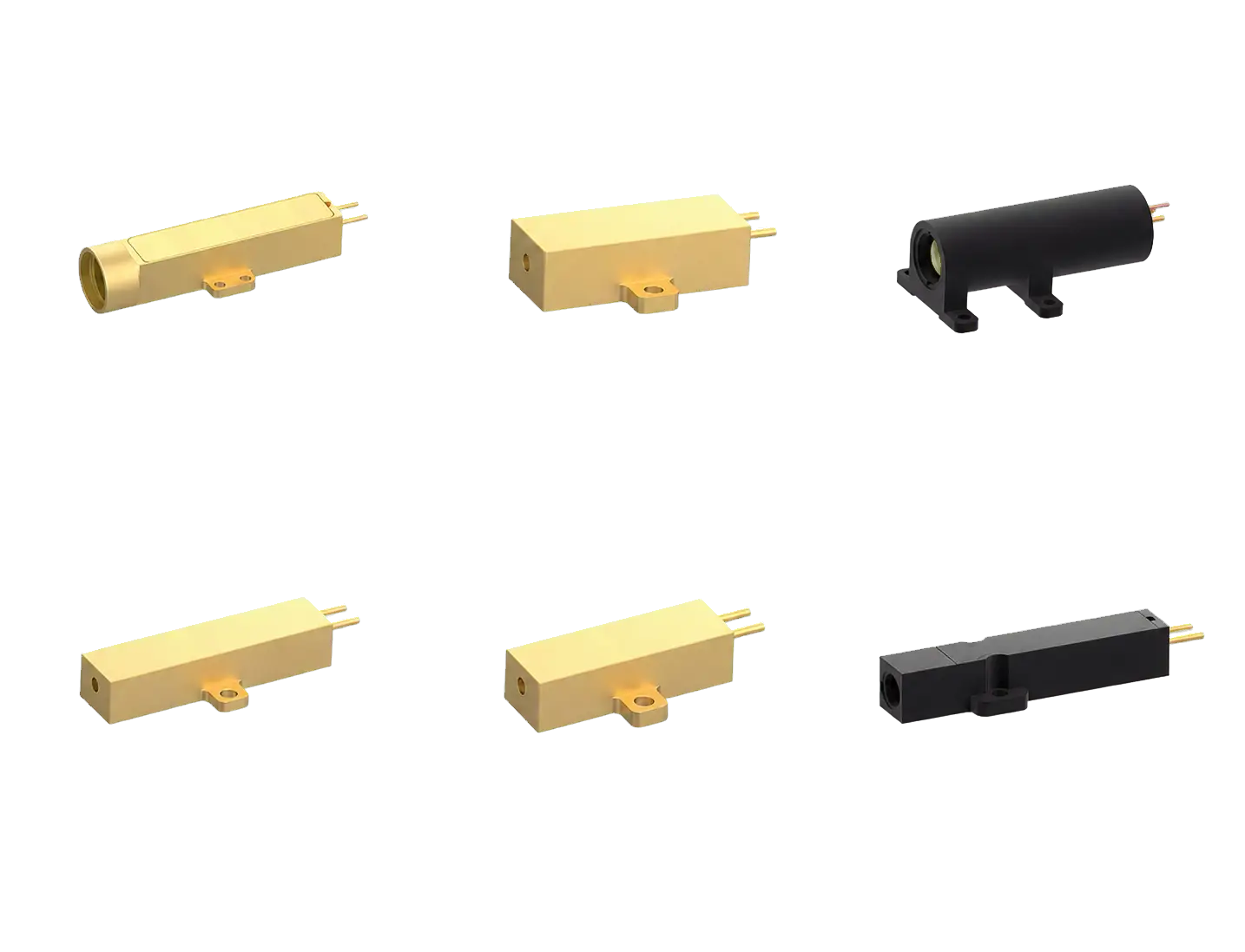
اقتران الألياف والتحكم في الطول الموجي لليزر الثنائي.
اقتران الألياف يحول الخرج غير المتماثل لواحد أو أكثر من بواعث الديود إلى واجهة ألياف محددة. النتيجة هي مصدر يمكن توجيهه ودمجه وصيانته بشكل أكثر قابلية للتنبؤ.
تهيئة الحزمة · محاذاة نشطة · توصيل الأليافكفاءة اقتران عالية تعتمد على مطابقة الفضاء البصري للباعث مع قلب الألياف وفتحتها العددية. يتطلب ذلك تشكيل الحزمة، والتحكم في المحاذاة، والتثبيت المستقر، وهيكل حراري لا يسحب المسار البصري من موضعه.
قطر النواة والفتحة العددية
تحدد نواة الألياف والفتحة العددية مساحة الاستقبال للحزمة المركّزة. كما تؤثر على السطوع المُسلَّم، وحساسية الانحناء، والبصريات اللاحقة.
المحاذاة النشطة
يتم تحسين الاقتران أثناء مراقبة القدرة الضوئية. تساعد المحاذاة الآلية في العثور على أعلى موضع قيمة والاحتفاظ به قبل تثبيت التجميع.
تثبيت الطول الموجي الاختياري
تستخدم تكوينات مصدر الضخ المحددة قفلًا طيفيًا لتضييق الإخراج وتقليل حركة الطول الموجي مع التيار أو درجة الحرارة، مما يدعم الضخ الحساس للامتصاص.
إدارة الانعكاس الخلفي والواجهة
تتم مراجعة حالة الموصل، ونظافة سطح النهاية، والتعرض للضوء المرتجع، ونصف قطر الانحناء، والتبريد الموصل كجزء من المسار البصري المثبت.
تقلل واجهة الألياف المتحكم بها من أعمال المحاذاة في الفضاء الحر داخل أداة العميل وتجعل اختيارات الطول الموجي، والقدرة، ونواة الألياف، والموصل، والحزمة أسهل في التحديد معًا.
تقنية ليزر الألياف النبضية 1.5 ميكرومتر لـ LiDAR.
لوميكسيس ليزر الألياف النبضية 1.5 ميكرومتر تجمع المنصات بين توليد النبض، وتضخيم الألياف، والمراقبة، والتحكم في التشغيل، والتصميم الحراري في تنسيقات مدمجة جاهزة للتكامل.
نطاق 1.5 ميكرومتر · تشغيل خارجي · إخراج مرجعييفصل مصدر الألياف النبضي تعريف النبضة عن توسيع القدرة. تتشكل النبضة عند قدرة منخفضة، وتُضخَّم عبر مسار ألياف متحكم به، وتُسلَّم عبر واجهة إخراج مستقرة. يتم اختيار الطوبولوجيا البصرية الفعلية حسب الطراز وهدف الأداء.
القدرة القصوى ومتوسط القدرة
يحدد عرض النبضة، ومعدل التكرار، وطاقة النبضة معًا القدرة القصوى ومتوسط القدرة. رفع معلمة واحدة يمكن أن يغير الحمل الحراري، وتشبع الكسب، والسلوك غير الخطي في أماكن أخرى.
التحكم الطيفي وغير الخطي
يتم هندسة توزيع الكسب، وطول الألياف، ونقطة التشغيل للحفاظ على الانبعاث التلقائي المضخم والتشويه غير الخطي ضمن الحدود المحددة للطراز.
التشغيل ومرجع التوقيت
يمكن للتشغيل التفاضلي الخارجي وإخراج بصري مرجعي مواءمة الانبعاث مع إلكترونيات المسح أو الالتقاط أو قياس المدى مع دعم توصيف التأخير.
المسار الحراري الموصل
يتطلب الإخراج المستقر سطح تركيب محددًا، وقوة تثبيت متساوية، ومسارًا حراريًا منخفض المقاومة إلى غلاف العميل أو اللوحة الباردة.
يقلل تسليم الألياف، والتحكم الإلكتروني، والتوقيت المرجعي من عدد الوظائف المنفصلة التي يجب على فريق OEM تجميعها حول المصدر البصري.
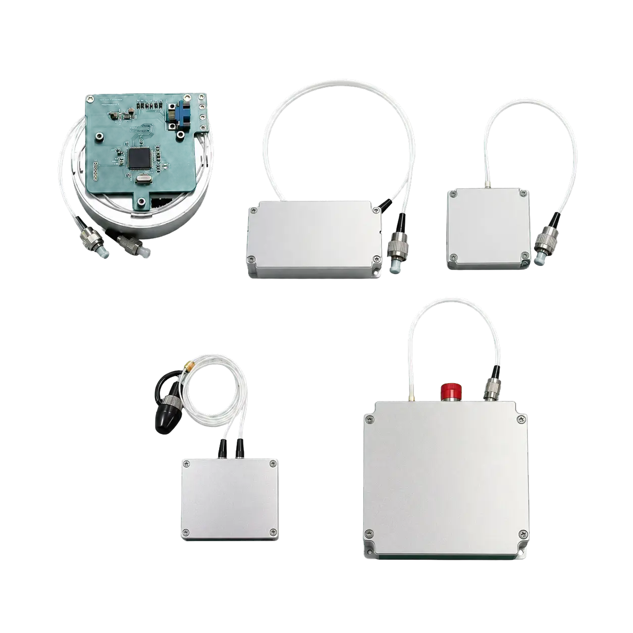
إلكترونيات وواجهات مستقبل جهاز قياس المدى بالليزر.
تربط سلسلة المستقبل والتحكم الأداء البصري بالنظام المضيف. يجب أن تحل الإشارات الضعيفة، وتتحمل العوائد القوية، وتتواصل بشكل متوقع تحت ظروف التشغيل الحقيقية.
APD · الواجهة الأمامية التناظرية · التوقيت · UART / TTL / RS422في جهاز قياس المدى، تحدد الإلكترونيات متى يتم إطلاق النبضة، وكيف يتم التعرف على العائد، وكيف يتم الإبلاغ عن قيمة المدى. يتم هندسة كسب الكاشف، وعرض نطاق الواجهة الأمامية، ودقة التوقيت، ومنطق العتبة كسلسلة إشارة واحدة.
استقبال صدى APD
يوفر الصمام الثنائي الضوئي الانهياري كسبًا داخليًا للإشارات الضوئية الضعيفة العائدة. يجب أن تراعي إعدادات الانحياز والكسب درجة الحرارة والضوضاء والضوء الخلفي ونطاق الصدى المتوقع.
النطاق الديناميكي التناظري
يجب أن تكتشف الواجهة الأمامية الأصداء الضعيفة البعيدة مع تجنب التشبع أو التلف الناتج عن الانعكاسات القريبة القوية غير المتوقعة. تُؤخذ استراتيجيات الحماية البصرية والإلكترونية في الاعتبار معًا.
التوقيت والمعايرة
تتأثر الدقة بشكل النبضة وعرض نطاق الكاشف وسلوك المقارن ودقة الساعة والتأخيرات الثابتة. تقوم المعايرة بربط الفاصل الزمني المُقاس بالمسار البصري الفعلي.
الاتصال مع النظام المضيف
تدعم الواجهات التسلسلية ومجموعات الأوامر المحددة التحكم في قياس المدى وتقارير الحالة والتطوير الثانوي. يتم تأكيد مستوى الواجهة والبروتوكول لكل طراز.
تؤثر النوافذ البصرية واستراتيجية التأريض وجودة الإمداد وجلوس الموصلات ومستوى الاتصال والتركيب الميكانيكي على النتيجة المُقاسة. تبدأ مراجعة الواجهة قبل تركيب الوحدة.
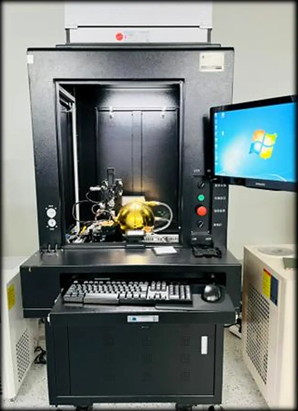
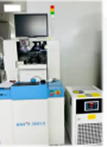
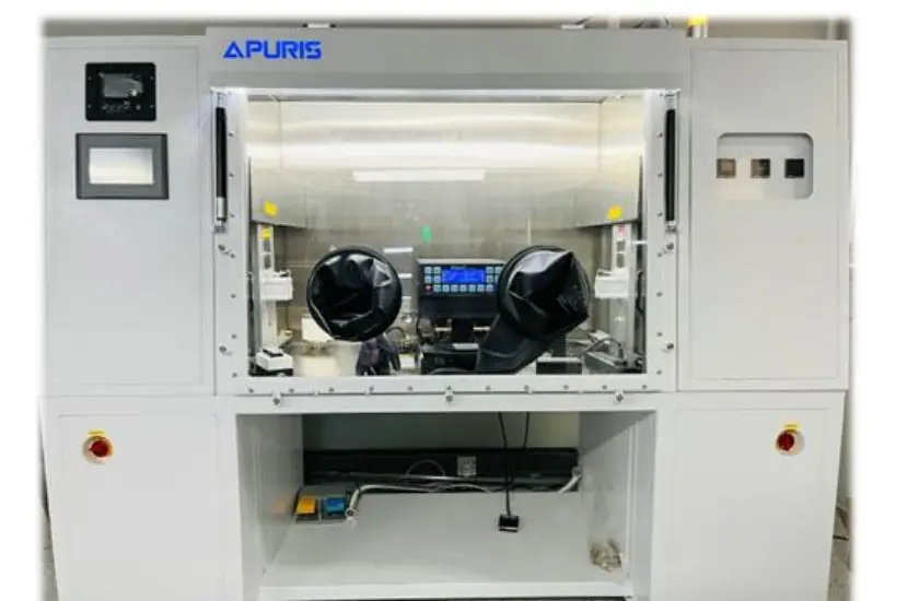
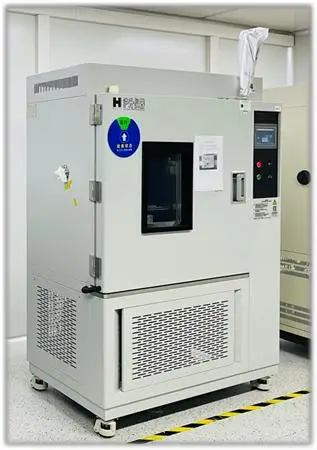
تغليف الليزر الدقيق واختبار الموثوقية.
يحافظ التغليف الدقيق على المسار البصري ويزيل الحرارة ويحمي الواجهات الحساسة ويحوّل النتيجة المخبرية إلى منتج قابل للتكرار. يُغلق التحقق الحلقة بين نية التصميم ومخرجات الإنتاج.
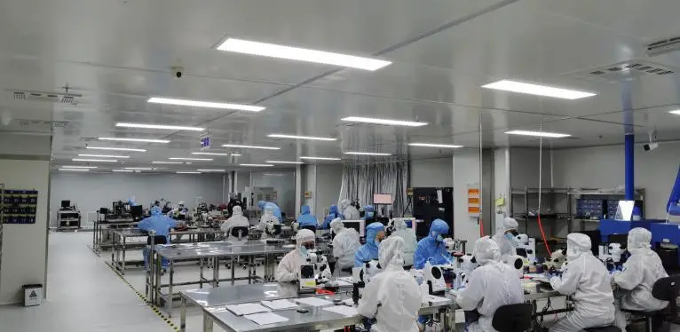
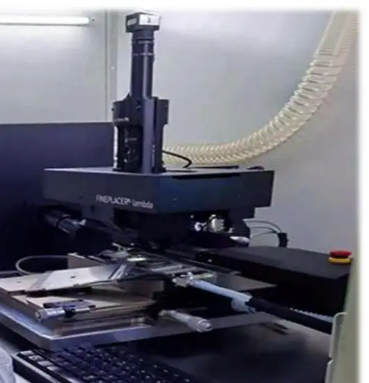
المسار الحراري أولاً
تؤثر درجة حرارة الوصلة واستواء التركيب ومادة الواجهة وقوة التثبيت على المخرجات وطول الموجة وعمر التشغيل. إزالة الحرارة جزء من التصميم البصري.
التموضع على مستوى الميكرون
يحدد ترابط الرقاقة والمحاذاة البصرية واقتران الألياف الهندسة التي تحدد توصيل الحزمة وكفاءتها.
التوصيلات البينية المحمية
يخلق ترابط الأسلاك وإعادة التدفق وإحكام غلق الحزمة واجهات كهربائية وميكانيكية وبيئية مستقرة.
قياس وفحص وتحقق
يحدد التوصيف البصري والتقادم ودورات درجات الحرارة وفحص الأبعاد وفحوصات الأداء النهائية التباين قبل الإصدار.
مواصفات مصدر الليزر والسلامة وتكامل OEM.
الأداء الخاص بالطراز
يجب تأكيد طول الموجة والمخرجات والنبضة والنطاق البيئي وقيم الواجهة مقابل ورقة البيانات الحالية والوثائق الخاصة بالطلب.
نتائج على مستوى النظام
تعتمد مسافة القياس والدقة والكفاءة البصرية والاستقرار الحراري على كل من المصدر وطريقة دمجه في النظام النهائي.
سلامة الليزر والامتثال
تصنيف الليزر والحالة التنظيمية خاصان بالمنتج والتكوين. استخدم تقرير الاختبار والملصق وتعليمات التكامل المعمول بها بدلاً من افتراض يعتمد على طول الموجة فقط.
مراجعة OEM
يراجع مهندسو Lumexis المتطلبات البصرية والكهربائية والحرارية والميكانيكية وواجهات الاتصال معًا قبل التوصية بمنصة قياسية أو تكوين مصدر ليزر OEM.
اختر تقنية مصدر الليزر المناسبة لنظامك.
شارك طول الموجة أو هدف النبضة أو القدرة والواجهة البصرية والغلاف وظروف التشغيل وخطة التأهيل. سنساعد في تحديد بنية مصدر عملية ومسار تكامل.
Lumexis — مصادر ليزر دقيقة، مصممة للعالم الحقيقي.