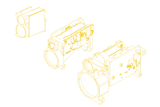
تصنيف 1535 ± 5 نانومتر لتكوين الوحدة المحدد.

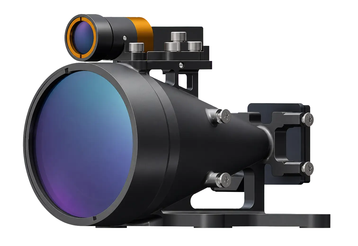
تقوم Lumexis بتطوير وتصنيع سلسلة وحدات تحديد المدى بالليزر الآمنة للعين من الفئة 1 بطول 1535 نانومتر، المبنية حول مصادر نبضات Er:Glass، وبصريات الإرسال والاستقبال، ومعالجة وقت الطيران بنبضة واحدة، واتصال TTL أو RS422. يتراوح الأداء المحدد بين ≥3.2–15 كم على هدف 2.3 × 2.3 متر وحتى ≥20 كم على هدف كبير، بدقة ≤±1 متر أو ≤±1.5 متر، وقياس قابل للضبط 1–10 هرتز، وإدخال DC 5–28 فولت، وحزم تبدأ من 33 ± 1 غرام. الحجم المضغوط، واستهلاك الاستعداد ≤0.2 واط، وملفات هندسية خاصة بالطراز تدعم التكامل في الأنظمة المدنية للطائرات بدون طيار رسم الخرائط وقياس الارتفاع، وأدوات المسح، والسكك الحديدية و فحص البنية التحتية, الليدار وأنظمة الاستشعار عن بُعد، والأدوات العلمية.
* ينطبق تصنيف السلامة للعين من الفئة 1 على تكوين الوحدة المحدد. يتطلب المنتج المضيف المكتمل تقييم سلامة الليزر في تكوينه البصري والتشغيلي النهائي.
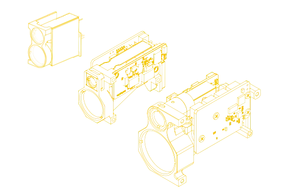
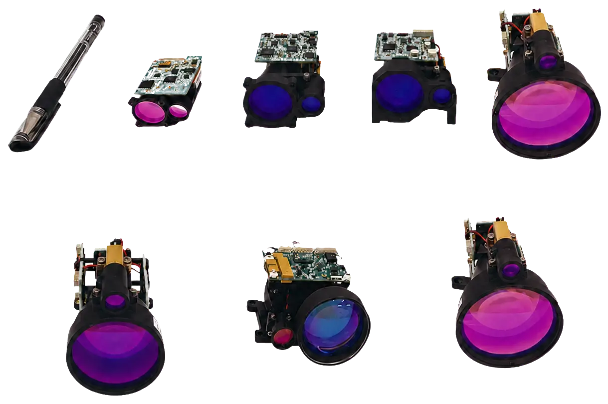
تصنيف 1535 ± 5 نانومتر لتكوين الوحدة المحدد.
محدد لهدف كبير؛ حتى ≥15 كم على هدف 2.3 × 2.3 متر.
للطرازات من فئة 3–8 كم؛ ≤±1.5 متر لفئتي 10 كم و15 كم.
إخراج قابل للضبط لأوضاع القياس الفردي والمستمر.
يبدأ من 48 × 21 × 31 مم و33 ± 1 غرام للتكامل المحدود المساحة.
إدخال DC 5–28 فولت مع استهلاك استعداد ≤0.2 واط.
سلسلة 3–15 كم
جميع الطرازات المتاحة موضحة أدناه مباشرة. قارن الهدف والمسافة المستهدفين أولاً، ثم تحقق من فتحة الاستقبال، والحد الأدنى للمدى، والغلاف الميكانيكي، ومتطلبات الطاقة، واتصال المضيف قبل إصدار التصميم.
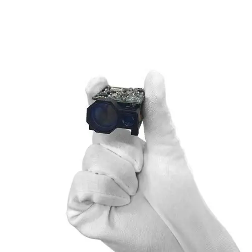
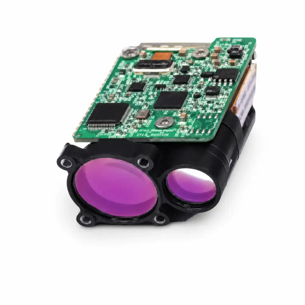
1535-LXCJ0300
≥3.2 كم على هدف 2.3 × 2.3 متر؛ ≥5 كم على هدف كبير؛ تباعد ≤0.6 مللي راديان.
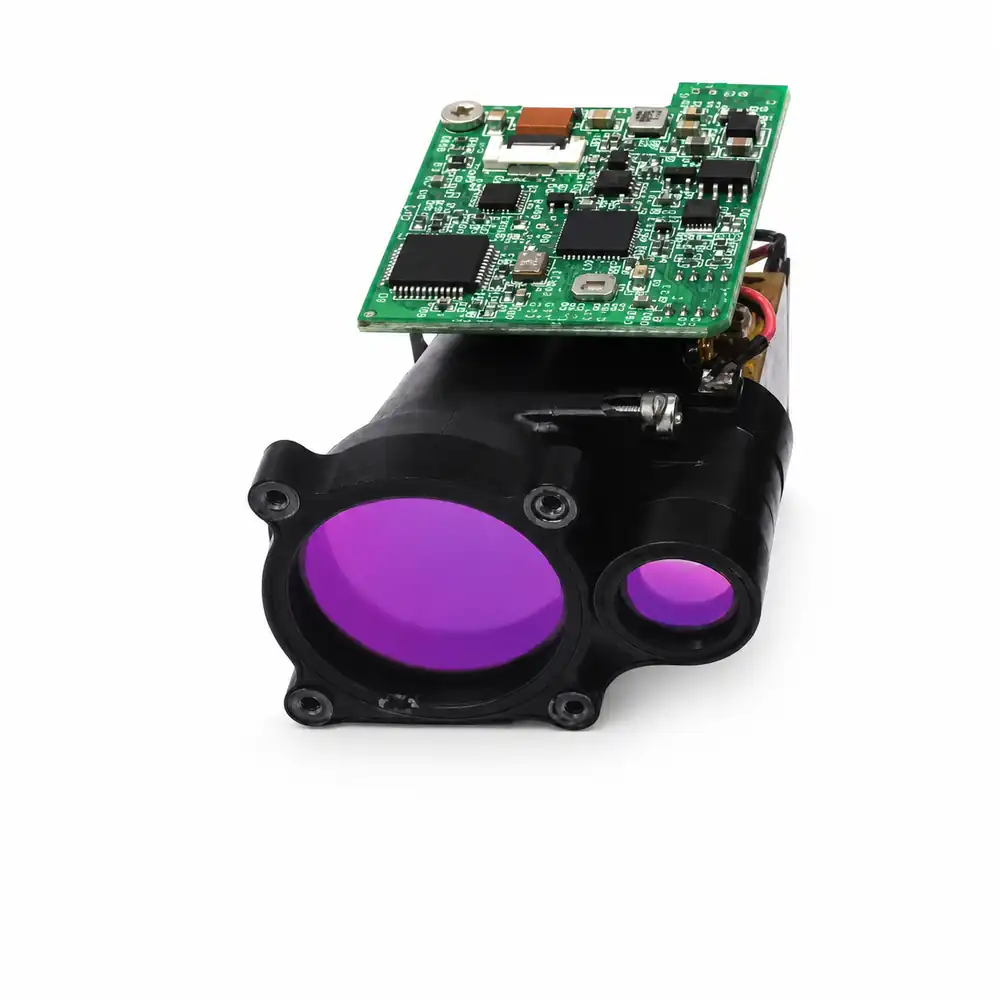
1535-LXCJ0500
≥5 كم على هدف 2.3 × 2.3 متر؛ ≥6 كم على هدف كبير؛ تباعد ≤0.3 مللي راديان.
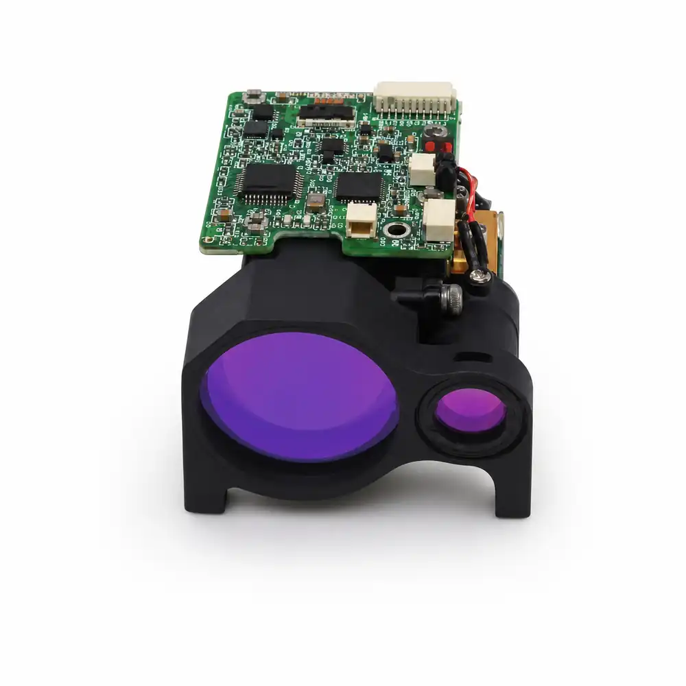
1535-LXCJ0600
≥6 كم على هدف 2.3 × 2.3 م؛ ≥7 كم على هدف كبير؛ تباعد ≤0.3 مكراد.
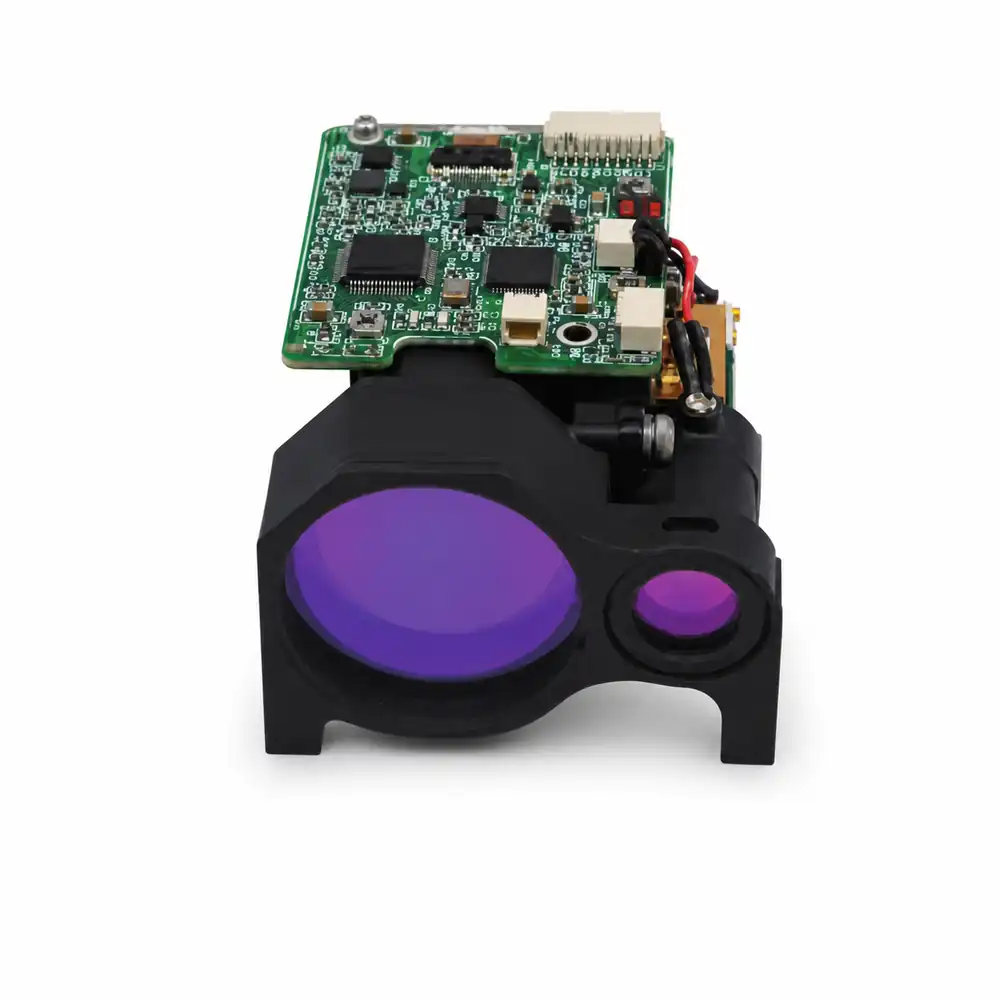
1535-LXCJ0700
≥7 كم على هدف 2.3 × 2.3 م؛ ≥8 كم على هدف كبير؛ تباعد ≤0.3 مكراد.
1535-LXCJ0800
≥8 كم على هدف 2.3 × 2.3 م؛ ≥10 كم على هدف كبير؛ تباعد ≤0.3 مكراد.
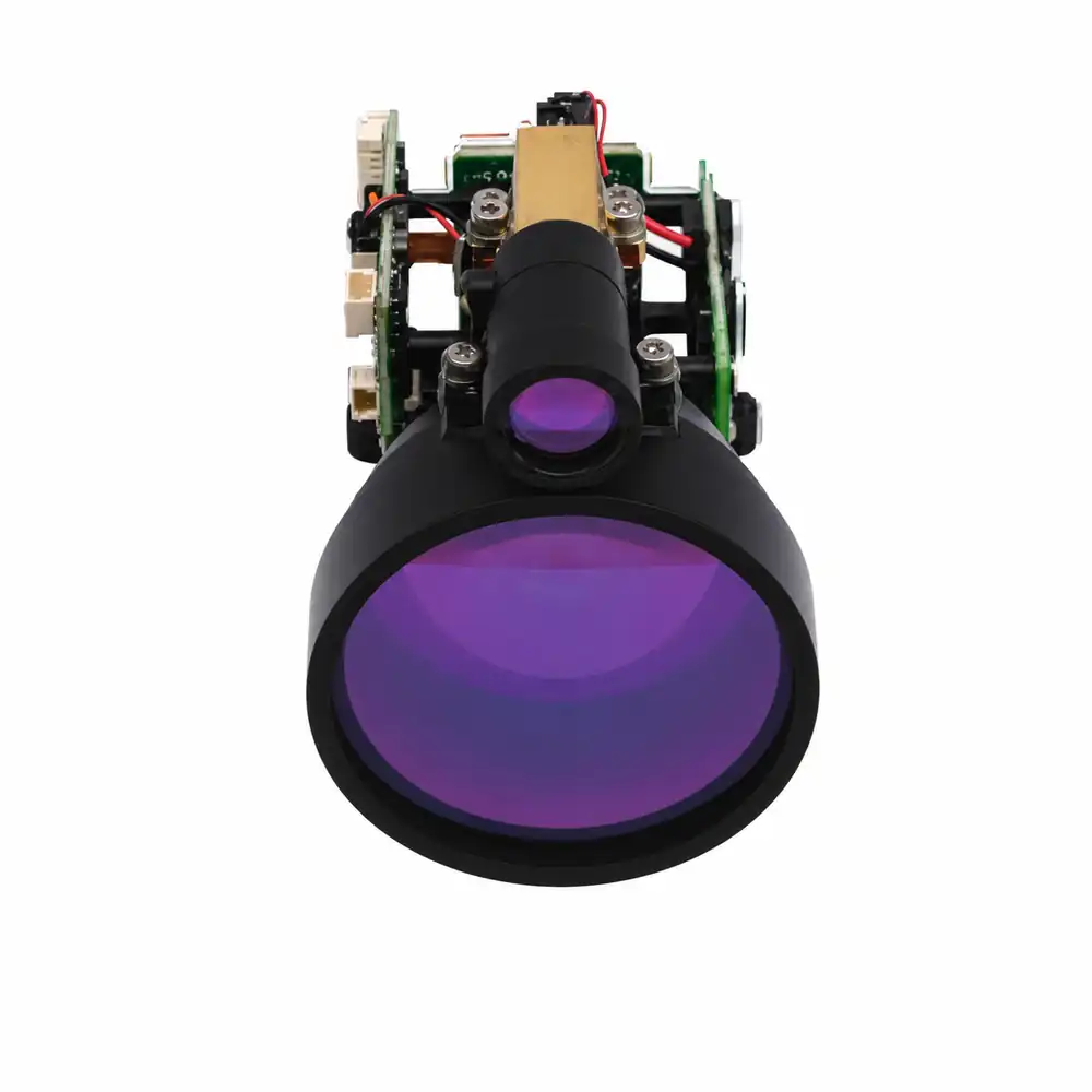
1535-LXCJ1000
≥10 كم على هدف 2.3 × 2.3 م؛ ≥12 كم على هدف كبير؛ تباعد ≤0.3 مكراد.
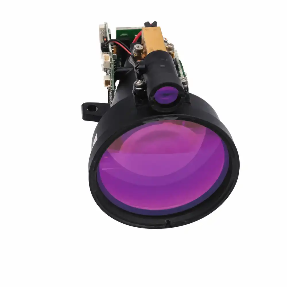
1535-LXCJ1500
≥15 كم على هدف 2.3 × 2.3 م؛ ≥20 كم على هدف كبير؛ تباعد ≤0.3 مكراد.
مصدر واحد لبيانات المواصفات
هذا هو قسم المواصفات الكامل الوحيد في الصفحة. جميع الأقسام الأخرى تشرح الاستخدام والتكامل والتسليم دون تكرار نفس مجموعة المعلمات.
| النموذج | هدف 2.3 × 2.3 م | هدف كبير | الحد الأدنى للمدى | الدقة | فتحة الاستقبال | الأبعاد | الوزن | الواجهة | الإدخال | متوسط القدرة | درجة حرارة التشغيل |
|---|---|---|---|---|---|---|---|---|---|---|---|
| 1535-LXCJ0300 | ≥3.2 كم | ≥5 كم | ≤15 م | ≤±1 متر | 16 مم | 48 × 21 × 31 مم | 33 ± 1 جم | RS422؛ خيار TTL | تيار مستمر 5–28 فولت | ≤0.8 واط عند 1 هرتز | −40 إلى +70°م |
| 1535-LXCJ0500 | ≥5 كم | ≥6 كم | ≤15 م | ≤±1 متر | 16 مم | 50 × 23 × 33.5 مم | ≤40 جم | TTL؛ خيار RS422 | تيار مستمر 5–28 فولت | ≤1 واط عند 5 فولت | −40 إلى +60°م |
| 1535-LXCJ0600 | ≥6 كم | ≥7 كم | ≤20 م | ≤±1 متر | 21 مم | 65 × 40 × 28 مم | ≤55 جم | RS422 | تيار مستمر 5–28 فولت | ≤1 واط عند 5 فولت | −40 إلى +60°م |
| 1535-LXCJ0700 | ≥7 كم | ≥8 كم | ≤30 م | ≤±1 متر | 25 مم | 65 × 46 × 32 مم | ≤72 جم | RS422 | تيار مستمر 5–28 فولت | ≤1 واط عند 5 فولت | −40 إلى +60°م |
| 1535-LXCJ0800 | ≥8 كم | ≥10 كم | ≤30 م | ≤±1 متر | 25 مم | 65 × 46 × 32 مم | ≤72 جم | RS422 | تيار مستمر 5–28 فولت | ≤1.3 واط عند 5 فولت | −40 إلى +60°م |
| 1535-LXCJ1000 | ≥10 كم | ≥12 كم | ≤50 م | ≤±1.5 م | 40 مم | 83 × 61 × 48 مم | ≤135 جم | RS422 | تيار مستمر 5–28 فولت | ≤1.5 واط عند 5 فولت | −40 إلى +60°م |
| 1535-LXCJ1500 | ≥15 كم | ≥20 كم | ≤70 م | ≤±1.5 م | 52 مم | 104 × 61 × 74 مم | ≤191 جم | RS422 | تيار مستمر 5–28 فولت | ≤2 واط عند 5 فولت | −40 إلى +60°م |
المواصفات العامة: آمن للعين من الفئة 1*، 1535 ± 5 نانومتر، نبضة واحدة TOF، قياس قابل للضبط 1–10 هرتز، استهلاك في وضع الاستعداد ≤0.2 واط، نطاق محدد وتقرير يصل إلى ثلاثة أهداف.
شروط المدى: تعتمد المسافة القصوى على حجم الهدف وانعكاسيته، والغلاف الجوي، والضوء الخلفي، والمحاذاة، ونفاذية نافذة المضيف. تأكد من شرط الاختبار الخاص بالطراز قبل إصدار التصميم.
مصمم ومصنع بواسطة Lumexis
نقوم بهندسة المصدر، وبصريات الإرسال والاستقبال، وإلكترونيات الكاشف، والهيكل، والمعايرة، والاتصال كسلسلة قياس واحدة. تتلقى فرق OEM واجهة بصرية وميكانيكية وبيانات محددة بدلاً من التوفيق بين مكونات غير مترابطة.
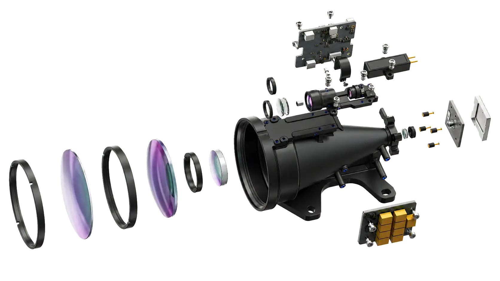
توليد نبضات مدمج بطول 1535 نانومتر لقياس المدى المباشر بزمن الطيران.
تباعد متحكم به، وجمع الإرجاع، ومحاور بصرية متوازية.
كشف الصدى، والتوقيت، والتصفية، وحساب المسافة المعايرة.
مراجع محددة واحتفاظ بالمحاذاة لتكامل قابل للتنبؤ.
معالجة الأوامر، والاختبار الذاتي، وأوضاع التشغيل، وإطارات الإخراج.
اكتساب بتحفيز من المضيف لتسلسلات قياس محكومة.
قياس متكرر بتردد تحديث قابل للتحديد.
إرجاع أسطح متعددة مكتشفة عندما يدعمها المشهد.
يحد من الإرجاعات المقبولة إلى فترة مسافة عمل محددة.
يوفر معلومات الحالة لبدء التشغيل وتشخيصات المضيف.
حلول التطبيقات
من وحدات مدمجة 33 ± 1 جم إلى تكوينات أهداف كبيرة ≥20 كم، تجمع السلسلة بين دقة ≤±1 م حسب الطراز، واستهلاك منخفض في وضع الاستعداد، وإخراج رقمي مع حزم مختارة للهدف الفعلي ومنصة المضيف.
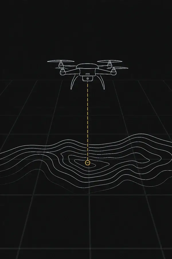
إدخال مسافة منخفض الكتلة لملفات تعريف التضاريس ورسم الخرائط وحمولات فحص البنية التحتية المدنية.
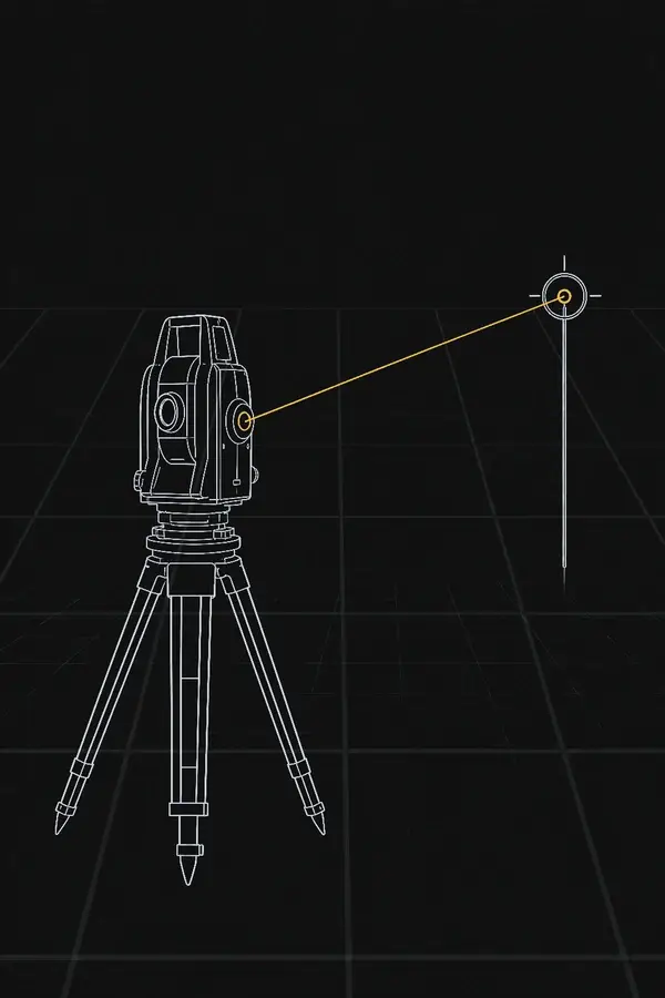
مخرجات رقمية متكررة للمدى لأجهزة قياس المسافة المحمولة والثابتة.
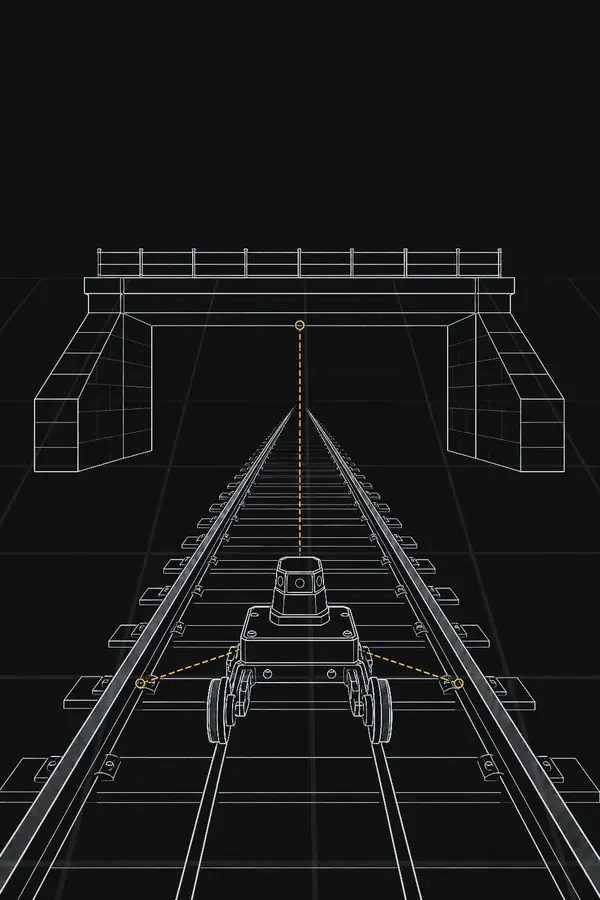
بيانات المسافة والخلوص والموضع الهيكلي لمعدات الفحص المتنقلة والثابتة.
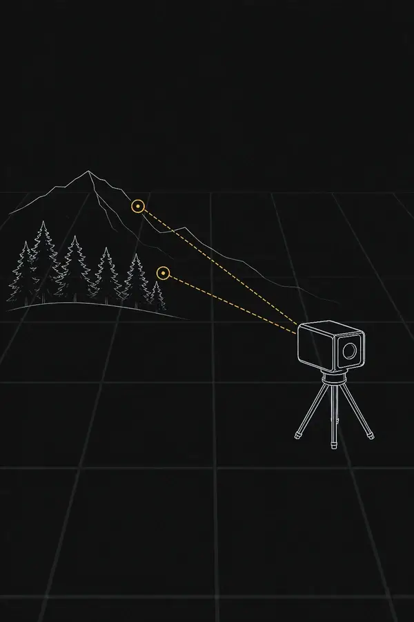
قياسات ذات بوابة مدى للاستشعار عن بُعد والمراقبة والأدوات التجريبية.
كتلة منخفضة، طاقة منخفضة، معدل التحديث، بصمة الهدف ومدى الميل المطلوب.
محاذاة الكاميرا أو المستشعر، الطوابع الزمنية، الاهتزاز، نافذة المضيف وتباينات الطاقة.
الحد الأدنى للمدى، دقة المسافة، الواجهة، نوع الهدف وحجم العلبة.
نفاذية النافذة البصرية، مرجع التركيب، توجيه الكابلات والتحقق من الهدف التمثيلي.
مدى الهياكل الكبيرة، استقرار المحاذاة، نطاق درجة الحرارة والمتانة الميكانيكية.
زاوية السقوط، مادة السطح، حركة المنصة، الاهتزاز والمحاذاة المحتفظ بها.
بوابة المدى، المخرجات متعددة الارتجاعات، اتساق التوقيت وتردد القياس.
يجب على المضيف توفير المسح أو التوجيه وبيانات الوضع ومعالجة سحابة النقاط عند الحاجة.
الوصول إلى البروتوكول، التكرار، استجابة الهدف وأوضاع التشغيل القابلة للتكوين.
تقييم على المقعد مع مصدر الطاقة النهائي والنافذة والتركيب وسلسلة اكتساب البيانات.
معرفة جهاز تحديد المدى بالليزر
تنتقل نبضة بصرية واحدة إلى الهدف وتعود إلى المستقبل. يقيس الوحدة زمن الرحلة ذهابًا وإيابًا، ويتحقق من الصدى ويحسب مسافة خط الرؤية.
تسلسل TOF بنبضة واحدة
لا يتم تحديد دقة المسافة بالمعادلة وحدها. دقة التوقيت، عرض نطاق الكاشف، نسبة الإشارة إلى الضوضاء للصدى، عمق الهدف، منطق العتبة والمعايرة تؤثر جميعها على النتيجة المُبلَّغ عنها.
مصدر Er:زجاجي وبصريات الإرسال تُطلق نبضة قصيرة بطول 1535 نانومتر.
فتحة الاستقبال تجمع جزءًا صغيرًا من الطاقة المنعكسة عن الهدف.
دائرة الكاشف والتوقيت تحدد الأصداء الصالحة وتقيس تأخير الرحلة ذهابًا وإيابًا.
معالجة الإشارات تطبق منطق البوابة والارتجاع قبل إخراج بيانات المسافة والحالة.
تباعد الشعاع وبصمة الهدف
التباعد يحدد مدى سرعة نمو البصمة المضيئة مع المسافة. يجب أخذه في الاعتبار مع خطأ التوجيه، استقرار المحور البصري ومجال رؤية المستقبل.
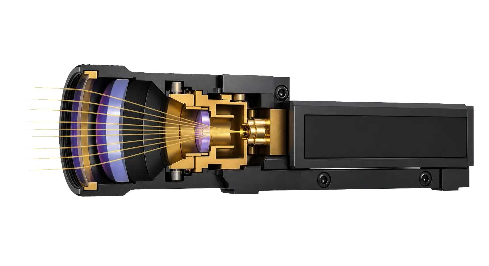 بصريات الإرسال
مصدر ليزر Er:Glass
التكوين البصري المعتمد على الطراز
يتم تحديد أصغر تكوين عند ≤0.6 ميلي راديان، بينما تُدرج معظم التكوينات طويلة المدى ≤0.3 ميلي راديان. التباعد الزاوي الأصغر يحسّن تغطية الهدف للأهداف المدمجة، لكنه يتطلب تحكمًا أدق في التوجيه ومحاذاة خط النظر.
| المدى | عند 0.3 ميلي راديان | المعنى الهندسي |
|---|---|---|
| 1 كم | ≈0.3 م | بصمة مدمجة؛ تظل المحاذاة مهمة. |
| 3 كم | ≈0.9 م | قابلة للمقارنة بالعديد من الأهداف المدنية الصغيرة. |
| 5 كم | ≈1.5 م | يصبح تغطية الهدف مصطلحًا رئيسيًا في ميزانية الوصلة. |
| 10 كم | ≈3.0 م | الأهداف الصغيرة تعترض جزءًا فقط من النبضة. |
ما الذي يحدد أقصى مدى
طاقة الليزر وحدها لا تحدد الأداء. يجب أن ينجو الصدى المفيد من انتشار الحزمة، والغلاف الجوي، وانعكاس الهدف، وفقدان التجميع، والضوء الخلفي، وعتبة كشف المستقبل.
يمكن أن تحسّن القدرة الذروية الأعلى قوة الإرجاع، لكن الطاقة وعرض النبضة ومعدل التكرار وحدود الفئة 1 ومتطلبات الطاقة والسلوك الحراري يجب أن تظل متوازنة.
الحزمة الضيقة تزيد كثافة الطاقة على هدف مدمج فقط عندما يظل خطأ التوجيه والاهتزاز وانجراف محاذاة خط النظر تحت السيطرة.
الضباب والمطر والثلج والجسيمات المحمولة جوًا تضعف وتشتت النبضة في كل من مساري الخروج والعودة. انخفاض الرؤية يقلل هامش المدى.
مساحة التجميع تتدرج مع D². فتحة أكبر تجمع طاقة إرجاع أكثر، مع زيادة حجم العبوة والكتلة ومتطلبات نافذة المضيف.
تتغير الطاقة المرتجعة مع المساحة المضاءة والانعكاسية الخاصة بالطول الموجي وملمس السطح والرطوبة وزاوية السقوط.
نفاذية النافذة والانعكاسات الشاردة وضوضاء الكاشف والضوء الخلفي ودقة التوقيت والكسب والبوابة كلها تؤثر على ما إذا كان الصدى مقبولًا.
حجم الهدف وانعكاسيته
قيمة الكيلومتر المذكورة ذات معنى فقط عندما تكون أبعاد الهدف وانعكاسيته والظروف الجوية معروفة.
جزء فقط من النبضة يصل إلى الهدف. هدف أصغر أو انعكاسية أقل أو زاوية سقوط أكثر انحدارًا يقلل الإشارة المرتجعة وبالتالي هامش المدى المتاح.
يمكن اعتراض معظم النبضة، لذا قد تُقاس الهياكل الكبيرة على مسافة أبعد من الهدف المرجعي 2.3 × 2.3 م. على مدى قصير جدًا، يمكن للأسطح عالية الانعكاس أيضًا أن تخلق إرجاعات مفرطة أو شاردة.
تصميم نافذة المضيف البصرية
Window material, coating, thickness, spacing and parallelism affect transmission, internal reflections and transmit-to-receive isolation. Validate the assembled host, not only the bare module.
1535 nm integration starting points
Use these values as initial mechanical guidance, then confirm them against the selected module drawing and the production window.
Command timing and host software
Typical F-series timing provides an integration starting point. Confirm the exact timing, baud rate, electrical levels and output frame in the protocol supplied with the selected model.
Typical preparation before emission, followed by approximately 4 ms for echo processing and result output.
Typical preparation while the ranging state is active, followed by processing and host reporting.
Distance results are reported at the configured measurement frequency. Host timing and buffering should follow the model protocol.
Mechanical and electrical integration
These are non-hermetic OEM modules. Use the model-specific drawing and protocol as the design baseline, and design the host enclosure to control dust, condensation and relative humidity at or below 80%.
Confirm the module envelope, mounting-hole depth, optical-axis position, connector location and service access before releasing the host enclosure.
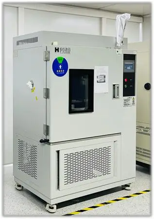
Testing, quality control and delivery
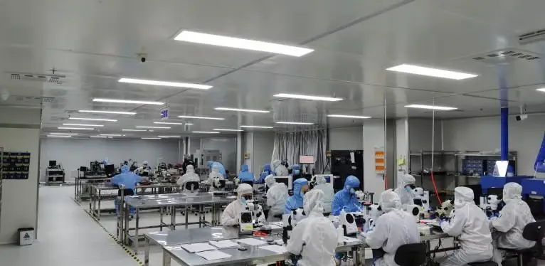
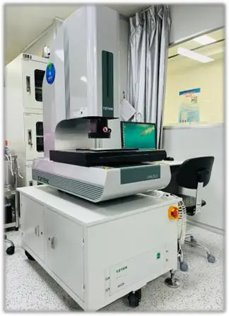
Laser output, optical-axis consistency, ranging accuracy, electrical behaviour and environmental performance are verified through defined production and release checks.
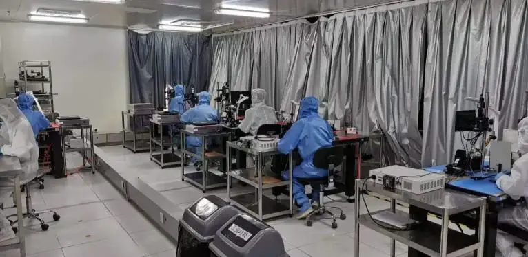
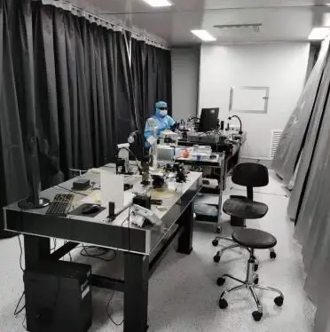
Dedicated workstations support Er:Glass source integration, transmit/receive alignment, circuit verification and calibrated ranging tests.
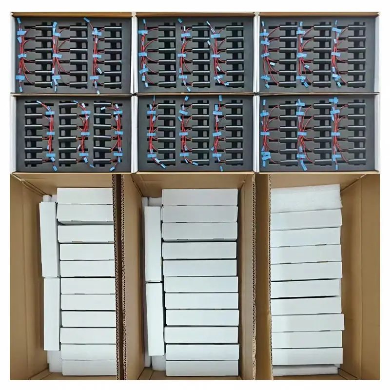
Individual protection keeps modules separated, secures cable tails and protects optical windows and connectors through handling and export transport.
Wavelength, pulse output, repetition frequency and output stability are checked against the model specification.
Transmit axis, receive field and mechanical reference are aligned and verified.
Distance output, valid-reading behaviour and target response are checked under defined test conditions.
Supply input, power demand, communication frames, self-test and operating modes are verified.
Specified operation is −40 to +60°C, with the 0300 model specified to +70°C.
Model data includes a 75 g @ 6 ms shock condition; vibration profiles are agreed for the intended host environment.
Each released module receives final electrical, communication, ranging and visual checks before packing.
Individual ESD-safe protection, separated shock-absorbing foam and moisture-control materials protect the module during storage and transport.
Optical windows and electrical connectors are protected separately; cable tails are restrained to prevent load transfer during handling.
Shipment can include model and serial-number labels, packing list and outgoing inspection record. Reinforced export packaging is available by shipment configuration.
Downloads and OEM / ODM support
Model-specific files keep dimensions, interfaces and operating limits tied to the quoted configuration. We also support host enclosure review, protocol integration and application-specific validation planning.
Request engineering filesOptical, electrical, mechanical and environmental specification.
Envelope, mounting features, optical axes and connector location.
Mechanical reference for enclosure and assembly-layout review.
Commands, output frames, status information and operating control.
Evaluation units, bench-test guidance, host software and integration support can be defined before design-in.
Interface, connector, cable, mounting envelope, protocol and validation-plan review for OEM / ODM projects.
الأسئلة الشائعة قبل البيع
These questions define the optical, electrical and mechanical configuration required for quotation, sample evaluation and design-in.
The model class follows the specified distance for a 2.3 × 2.3 m target. A larger target can provide a longer specified distance, which is why both target conditions appear in the comparison table.
Provide the target dimensions and material, expected reflectance where known, minimum and maximum distance, visibility, target or platform motion, available installation volume and mass, supply rail, communication interface, operating temperature and the planned host-window construction. These inputs are more reliable than selecting by maximum range alone.
Start with installation volume, weight limit, target and required distance. Models in the 3 km to 8 km classes provide the smallest envelopes, beginning at 48 × 21 × 31 mm and 33 ± 1 g. Receive aperture, minimum range, peak power demand and interface must still be confirmed before selection.
Class 1 eye-safe classification applies to the module in its defined model configuration. The completed host instrument must be assessed after its final window, enclosure, power control, firmware and operating modes are fixed. Applicable IEC 60825-1 requirements should be reviewed during system release.
No. Range changes with target dimensions, reflectance, incidence angle, atmosphere, background light, optical-window transmission and alignment. The model table uses stated target conditions so alternatives can be compared consistently; representative-target testing is recommended for the final installation.
Divergence determines how quickly the illuminated spot grows with distance. At 0.3 mrad, the added spot diameter is approximately 0.3 m at 1 km, 1.5 m at 5 km and 3 m at 10 km. If the target is smaller than the spot, only part of the transmitted energy is returned. Confirm whether a model's value is specified as full angle and include the initial beam diameter in detailed calculations.
Use flat, parallel optical glass with an anti-reflection coating for 1525–1545 nm and keep it close to the module. A practical design starting point is 2–4 mm glass thickness, an air gap of no more than 4 mm, at least 1.5 mm clear-aperture margin beyond the projected transmit and receive lenses, and at least 2 mm additional structural margin. Final dimensions must be checked against the selected model, installation angle and enclosure tolerances.
The series supports model-dependent DC 5–28 V input with TTL or RS422 communication. Power design must account for the model's peak current during laser emission, not only standby consumption of ≤0.2 W. Use the model-specific pin definition, voltage levels and grounding requirements before connecting a host controller.
Single-shot and continuous measurement are supported with an adjustable 1–10 Hz rate. The series can report up to three targets and supports range gating plus front or rear return handling. Exact commands, output frames and availability are defined in the selected model's communication protocol.
For typical F-series operation, allow approximately 800 ms for the first command after power-up plus about 4 ms processing time, and approximately 250 ms plus 4 ms for subsequent commands. Continuous output can be set from 1 to 10 Hz. Confirm timing, baud rate and host timeout against the protocol supplied with the quoted model.
No. These are non-hermetic OEM modules. The host enclosure must control dust, condensation and relative humidity at or below 80%, while keeping the transmit and receive apertures clear.
Baud-rate options depend on the model and protocol. Pulse energy and divergence are optical safety and calibration parameters and are not assumed to be field-adjustable; any factory change requires an engineering review of range performance, power, thermal behaviour and the defined Class 1 configuration.
Model-dependent evaluation units, test guidance, datasheets, 2D drawings, 3D STEP files, connector definitions and communication protocols are available for design review. Connector, cable, mounting envelope, interface and command integration can be evaluated against the project requirements and validation plan.
Compliance and test documents are supplied only when they are applicable to, and verified for, the quoted configuration. Share the destination market and required document list during quotation so availability can be confirmed. The completed host product remains subject to its own laser-safety and product-compliance assessment.
We will recommend a model, identify the main integration risks and prepare the relevant engineering document package.