
Machine vision
Machine Vision Lasers: Build Around the Inspection Result
Lumexis supplies 525 nm fiber-coupled lasers for controlled narrowband illumination and laser-line projection in industrial machine vision and optical inspection equipment.
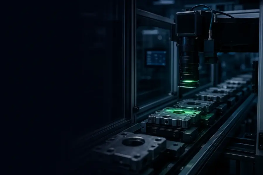
Lumexis supplies 525 nm fiber-coupled lasers for machine vision systems that need a remotely delivered green source for controlled illumination or laser-line projection. The source can support high-contrast 2D inspection, profile measurement and structured-light tasks when it is matched to the camera, filter, beam-shaping optics and inspection geometry.
This is not a camera or a complete vision system. It is the optical-source layer of an OEM solution. We help equipment builders define that layer around the actual field of view, exposure time, target material, working distance, fiber route and thermal envelope—because nominal laser power alone does not determine image quality or measurement repeatability.
Match the source to the inspection task
| Inspection task | Recommended optical approach | What the engineering team should define first |
|---|---|---|
| Surface presence, edge or feature inspection | 525 nm narrowband illumination with a matched camera filter | Target reflectance, field of view, required contrast and exposure time |
| Scratch, burr and texture detection | Low-angle or shaped illumination | Defect orientation, surface roughness, glare and acceptance threshold |
| Contour and profile measurement | Green laser line with camera triangulation | Line width, working distance, baseline, scan speed and calibration volume |
| Gap, step and height inspection | Structured laser line or multiple projected profiles | Required depth repeatability, occlusion risk and part-position tolerance |
| High-speed production inspection | Fiber-delivered source with controlled beam shaping | Cycle time, duty cycle, trigger scheme and thermal stability |
Fast selection rule: start with the feature that the camera must separate from its background. Then choose illumination geometry, wavelength and filtering. Only after those choices should optical power be scaled to the line length, aperture, exposure time and process speed.
Where a 525 nm fiber-coupled source fits
Green light can provide useful response from many silicon-based monochrome cameras and can create strong visible contrast on selected materials. It is also convenient for setup because the projected pattern is visible. The real benefit of fiber delivery, however, is architectural: the laser package can be mounted away from the inspection head while a flexible fiber routes optical power to a compact line generator, diffuser or other beam-shaping assembly.
That separation can help an OEM team:
- reduce mass and heat near a camera or scanning head;
- place the source where cooling and service access are easier;
- use interchangeable output optics for a spot, line or illumination field;
- maintain a cleaner mechanical boundary between the light source and the calibrated imaging geometry;
- standardize one source platform across related inspection stations.
Green is not automatically the best wavelength for every part. Pigments, coatings, polished surfaces, translucent materials and camera sensor response can all change the result. Sample testing with the intended camera and lens remains the reliable way to confirm contrast.
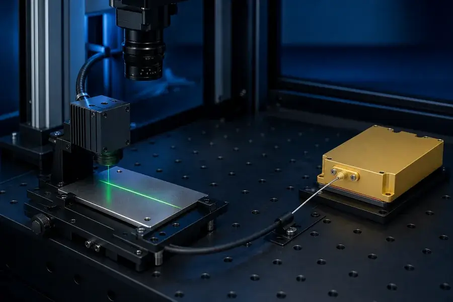
System architecture
Review the complete optical and measurement chain
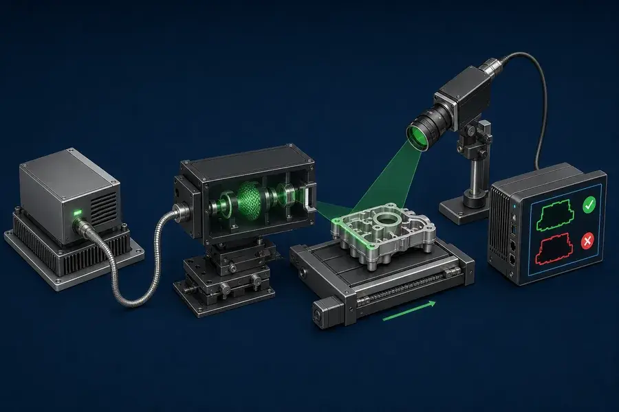
Fiber-coupled green laser source integrated with beam shaping, target and camera
Two common system architectures
1. Controlled narrowband illumination for 2D inspection
The fiber output is expanded or diffused to illuminate a defined region. A filter in front of the camera lens passes the useful green band while suppressing part of the broadband ambient light. This architecture can support presence/absence checks, feature location, edge detection, surface inspection and image-based measurement.
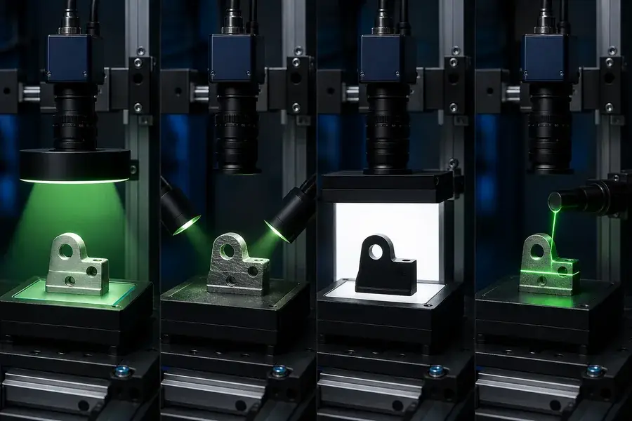
The illumination geometry determines what becomes visible:
- Bright-field illumination directs reflected light toward the camera and is useful when broad flat areas should appear bright.
- Dark-field illumination uses low-angle light so edges, raised features and some surface defects scatter into the camera against a darker background.
- Diffuse illumination reduces distracting reflections from curved or glossy surfaces.
- Backlighting creates a silhouette for edge location, hole inspection and dimensional gauging. A fiber-coupled laser is usually considered only when its source characteristics add value; many backlight tasks are better served by a conventional area light.
Measurement principle
Connect the optical measurement to system geometry
Bright-field, dark-field, backlight and laser-line machine-vision geometries
2. Laser-line projection for 3D profile measurement
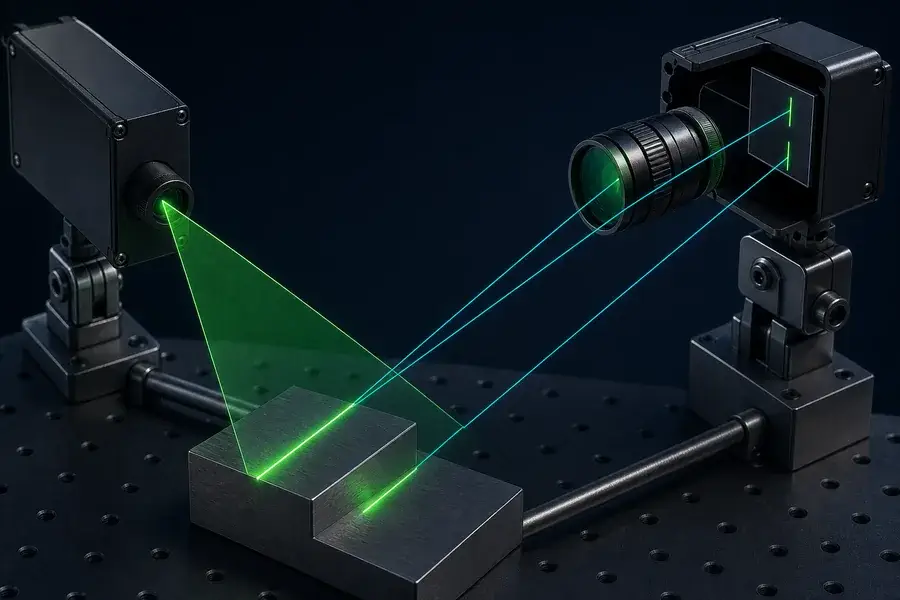
In laser triangulation, an output optic projects a line onto the object. A camera observes that line from a different angle. Changes in surface height move the line to a different position on the camera sensor; the calibrated system converts that sensor position into a height or profile value.
The source contributes the projected line, but depth performance is set by the complete geometry. Baseline, camera angle, lens, sensor sampling, line width, surface scattering, exposure and calibration all interact. A brighter line may improve signal in a short exposure, but it cannot correct poor geometry, saturation, occlusion or an unstable mechanical frame.
Measurement principle
Connect the optical measurement to system geometry
Conceptual laser triangulation geometry with a green projected line and camera observation paths
The optical chain: source power is only the starting point
An inspection system should be evaluated from the fiber output to the image data:
- 525 nm laser source — establishes optical power, spectral behavior, operating mode and electrical/thermal requirements.
- Fiber delivery — defines core size, numerical aperture, connector or termination, routing limits and coupling to downstream optics.
- Beam shaping — forms a spot, line or field and controls line length, thickness, divergence and uniformity.
- Part interaction — reflectance, color, texture, slope and contamination determine how much useful light reaches the camera.
- Imaging optics and filter — lens aperture, field of view, focus and filter transmission determine the signal and background reaching the sensor.
- Camera and exposure — quantum efficiency, pixel size, gain, shutter time and line rate determine the captured image.
- Calibration and processing — converts contrast or projected-line position into a pass/fail result or measurement.
System architecture
Review the complete optical and measurement chain
Optical chain from 525 nm source through fiber, beam shaping, workpiece and filtered camera
Parameters that belong in the source specification
Wavelength and wavelength tolerance
Specify the source wavelength together with the camera filter and sensor response. A narrowband filter can improve the ratio of useful illumination to ambient background, but the filter must transmit the actual source spectrum across the operating temperature. Interference filters also shift their passband with angle of incidence, which matters with wide-angle lenses and large fields of view.
Delivered power—not just source rating
Define where power is measured: at the module output, at the fiber end or at the workpiece after beam-shaping optics. Transmission losses, line length, working distance and aperture can produce a large difference between source power and useful irradiance. The correct value is the minimum stable power that reaches the required camera signal without clipping highlights or heating the target unnecessarily.
Fiber core and numerical aperture
The fiber core affects étendue, output spot characteristics and compatibility with line generators or homogenizers. Numerical aperture defines the output cone that downstream optics must accept. These parameters should be selected with the complete output optic, not treated as interchangeable connector details.
Output termination and fiber routing
The connector, ferrule, pigtail length, bend management and strain relief have direct mechanical consequences. The inspection head should protect the fiber from repeated tight bending, contamination and unintended load. If the fiber is part of a moving axis, routing and life testing should represent the real motion profile.
Spatial uniformity and line quality
For area illumination, confirm uniformity across the camera field rather than at one point. For triangulation, define line width, straightness, intensity distribution and focus across the full measurement width. A narrow central line that widens or curves at the ends may limit usable calibration volume.
Temporal stability and control
Confirm whether the system operates continuously or in a triggered cycle. Camera exposure and laser timing must be coordinated if the source is modulated. Include warm-up behavior, short-term fluctuation and long-duration drift in validation where the algorithm depends on a stable intensity threshold.
Thermal interface
Electrical input not converted into optical output becomes heat. The equipment must provide an appropriate mounting surface, heat flow path and temperature monitoring strategy. Optical alignment, output level and lifetime can all be affected by operation outside the agreed thermal conditions.
Managing contrast, glare and speckle
Machine vision is a contrast-engineering problem. The best optical setup makes the feature of interest change strongly while normal variation in the rest of the image changes as little as possible.
Pair green illumination with the target material
An object that reflects green strongly may appear bright under 525 nm illumination; a material that absorbs it may appear darker. This can help separate colored features, but real coatings rarely behave like ideal color charts. Test production samples, including acceptable color variation, contamination and aging.
Use filtering as a system component
A green bandpass filter can reduce broadband factory lighting reaching the camera. Its center wavelength, bandwidth, peak transmission, blocking range and angle sensitivity should be matched to the laser, lens and field of view. Filtering improves optical selectivity; it does not remove glare created by the inspection geometry.
Control specular reflections
Polished metal and glossy coatings can send a concentrated reflection into the camera and saturate pixels. Change the lighting or camera angle first. Diffusion and polarization may help in suitable geometries, but each adds transmission loss and must be checked against the target surface.
Treat speckle as a measurement-noise source
Laser illumination on rough surfaces can create granular intensity variation. Multimode-fiber output can also show a mode-dependent pattern. Depending on exposure time and spatial resolution, mitigation may include a moving diffuser, controlled mode mixing, optical averaging, polarization diversity or algorithmic averaging. The method must be validated at the actual camera exposure and scan speed; a device that averages well for a long exposure may not help a fast line-scan process.
Lumexis 525 nm source range for evaluation
The following published models provide starting power classes for OEM discussion. The final fiber core, numerical aperture, output termination, electrical drive and package should be confirmed against the current order-specific specification.
| Model | Published optical power | Typical evaluation position |
|---|---|---|
| 525-LXGX0003 | 3.2 W | Compact or lower-throughput optical evaluation |
| 525-LXGX0004 | 4 W | Controlled illumination and line-generation trials |
| 525-LXGX0005 | 5 W | Higher irradiance or longer projected patterns |
| 525-LXGX0015 | 15 W | High-throughput OEM inspection development |
| 525-LXGX0020 | 20 W | Larger fields or demanding optical-loss budgets |
| 525-LXGX0035 | 35 W | High-power source integration with dedicated thermal design |
| 525-LXGX0070 | 70 W | Specialized high-power OEM optical platforms |
These rows are not a direct recommendation that more power produces better inspection. For many camera systems, optical attenuation or a lower-power model is preferable to operating near saturation. Selection begins with the irradiance required at the target and works backward through the optical losses.
Integration workflow for OEM equipment
Step 1: define the measurement
Provide the smallest defect or dimensional change, field of view, working distance, cycle time and acceptable repeatability. For a laser line, include required line length and depth range.
Step 2: characterize representative samples
Use real parts at the limits of acceptable surface finish, color, slope and contamination. Include failure samples that the system must detect. A visually attractive image is not sufficient; the chosen configuration must separate the algorithm’s decision classes.
Step 3: select geometry, camera and filter
Choose the illumination angle and imaging angle before finalizing source power. Confirm sensor response near 525 nm and check that the filter transmits the source over its expected spectral and angular range.
Step 4: specify the fiber and output optics
Translate the field of view and working distance into line or field requirements. Then match fiber core and numerical aperture to the beam-shaping optics. Include mechanical envelope, fiber exit direction and service access.
Step 5: close the power and thermal budget
Measure useful signal at the required exposure. Account for fiber and optic losses, expected contamination margin and any diffuser or polarization loss. Design heat removal around the selected operating point and duty cycle.
Step 6: validate repeatability
Test cold start, warm operation, ambient-light variation, production speed, part-position tolerance and the intended maintenance interval. For measurement systems, repeat calibration checks after thermal cycling and mechanical intervention.
Information to send for a configuration review
To recommend a practical 525 nm fiber-coupled laser starting point, send:
- inspection type: 2D illumination, line projection or structured pattern;
- target material, coating, color and surface finish;
- camera model, sensor type, lens and exposure time;
- field of view, working distance and required line or spot dimensions;
- conveyor or scan speed and duty cycle;
- required power at the workpiece, if already measured;
- preferred fiber core, numerical aperture, connector and length;
- module space, cooling method and ambient temperature range;
- electrical-control, monitoring and trigger requirements;
- annual quantity and prototype schedule.
With those inputs, we can review the source, fiber interface and operating conditions as one integration problem rather than quoting a wattage in isolation.
Frequently asked questions
Why use 525 nm for machine vision?
525 nm provides visible green illumination that can work well with many silicon-based monochrome cameras and selected target materials. It also supports highly visible laser-line setup. Suitability still depends on sensor response, surface reflectance, filters and inspection geometry, so sample testing is required.
Is a higher-power laser always better for a faster inspection line?
No. More delivered power may support a shorter exposure or a longer projected line, but excess irradiance can saturate the camera and reduce useful contrast. Camera aperture, gain, filter transmission, beam shaping and target reflectance must be considered together.
Can the fiber output connect directly to a camera system?
Normally the fiber output feeds beam-shaping optics such as a line generator, collimator, diffuser or homogenizer. Those optics define the illumination presented to the object. Their input acceptance must match the fiber core and numerical aperture.
Does a narrowband filter remove all ambient-light problems?
No. It can suppress light outside its passband, but sunlight or factory lighting with energy inside the band may remain. Wide-angle rays can also shift an interference filter’s passband. Optical shielding, stable exposure and good geometry are still important.
What determines depth accuracy in laser triangulation?
The complete calibrated geometry: camera and projector angles, baseline, lens, sensor sampling, projected-line width, surface response, signal quality and mechanical stability. The laser is an enabling source, not an independent accuracy specification.
Can one source support several inspection heads?
It may be possible with an engineered splitter and sufficient optical budget, but splitting changes delivered power, uniformity, connector count and failure behavior. Each channel should be measured at the workpiece, and the architecture should be reviewed for serviceability.
Build the optical source around the inspection result
Send us the target samples, camera details, geometry and cycle-time requirement. Lumexis will help map those inputs to a 525 nm source power class, fiber interface, output-optic concept and thermal integration plan for prototype validation and scalable OEM supply.
Lumexis — precision laser sources, engineered for the real world.