








Un valor pequeño de divergencia parece atractivo en una hoja de datos. Sin embargo, a largo alcance, un haz estrecho puede fallar un objetivo angosto cuando el error de alineación, el movimiento de la plataforma, la vibración o el movimiento del objetivo desplazan la huella fuera del punto previsto.
Hacer el haz más ancho no es una solución gratuita. La misma energía de pulso se distribuye sobre un área más grande, por lo que menos llega a un objetivo pequeño y más puede iluminar superficies en primer plano o fondo.
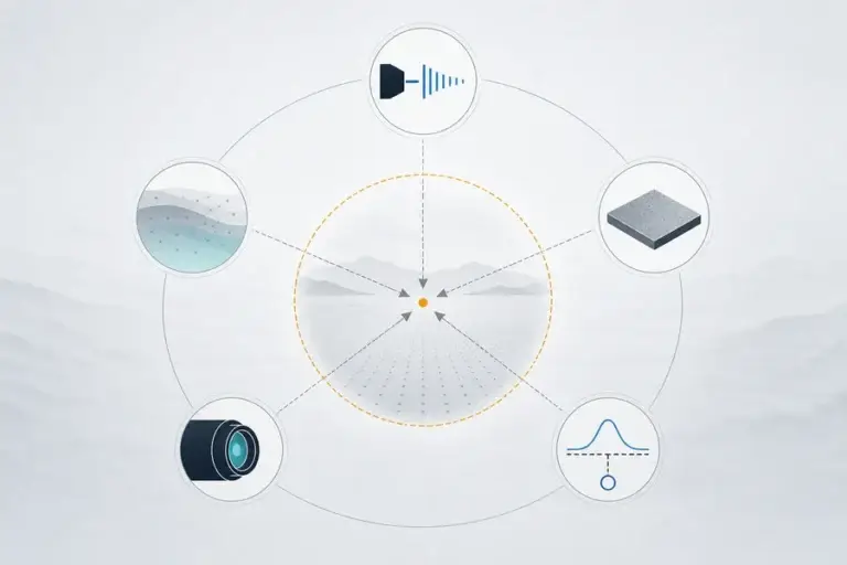
La divergencia del haz de un telémetro láser establece qué tan rápido crece la huella transmitida con la distancia. Una divergencia más estrecha concentra la energía y mejora la selectividad espacial, pero exige un apuntado más preciso. Una divergencia más ancha aumenta la cobertura geométrica, pero reduce la irradiancia en el objetivo y puede mezclar retornos. El mejor valor depende del tamaño del objetivo, la incertidumbre de apuntado, el alcance, el campo de visión del receptor y la probabilidad requerida de detección válida.
Qué Especifica Realmente la Divergencia del Haz de un Telémetro Láser
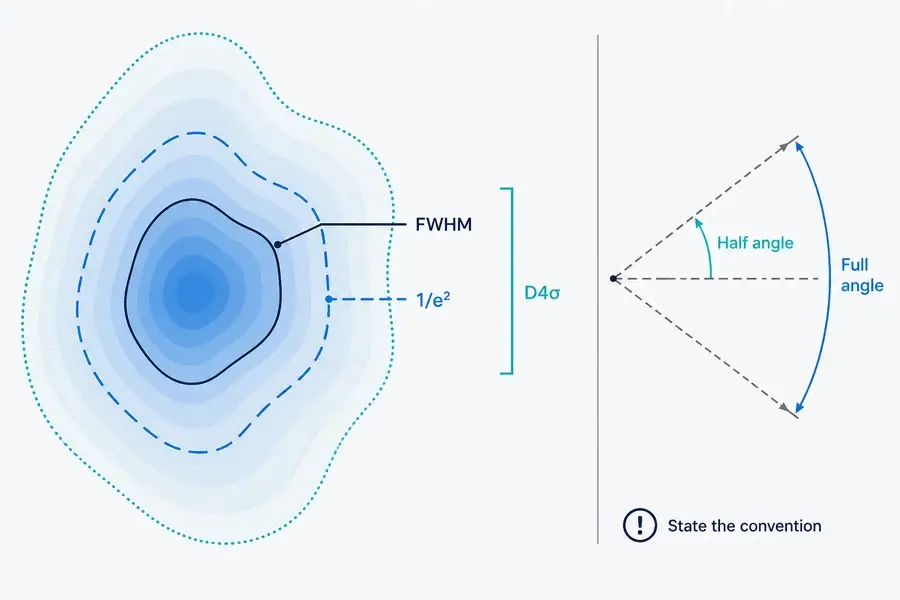
La divergencia del haz es una descripción angular del crecimiento del haz, comúnmente reportada en milirradianes. No es un cono de bordes duros. Los haces reales tienen una distribución de intensidad, y el límite citado depende de cómo se define el ancho del haz.
Para un haz gaussiano, el radio 1/e² es el punto donde la intensidad ha caído a aproximadamente el 13,5% de su valor en el eje. El ancho total a mitad de máximo (FWHM) describe una parte más estrecha de ese mismo perfil. ISO 11146 utiliza un enfoque de segundo momento, o D4σ, para mediciones de ancho de haz y propagación. Estos valores no deben compararse como si fueran intercambiables.
Una especificación completa indica si la divergencia es un ángulo completo o medio. Un haz elíptico necesita valores horizontal y vertical. Pregunte qué se midió, a lo largo de qué ejes, bajo qué condición y desde qué plano de referencia.
Nuestra guía sobre cómo un telémetro de pulsos mide la distancia explica la cadena separada de tiempo de ida y vuelta.
Convierta la Divergencia en una Huella a Distancia
Para un diámetro inicial del haz D₀, distancia de trabajo L, y divergencia de ángulo completo Θ, una estimación geométrica simple es:
D(L) = D₀ + 2L tan(Θ/2)
Cuando el ángulo es pequeño y se expresa en radianes, esto se convierte aproximadamente en D(L) ≈ D₀ + LΘ. Un milirradián por lo tanto añade aproximadamente un metro de diámetro por kilómetro, antes de considerar el diámetro inicial y otros efectos de propagación.
La estimación solo funciona cuando la convención es clara. Usar un medio ángulo como ángulo completo crea un error de factor de dos en el término de crecimiento. Calcule ambos ejes para un haz elíptico. Un objetivo inclinado también ve una huella alargada.
No trate el diámetro calculado como un límite nítido que contiene irradiancia igual. El perfil del haz, la truncación, los efectos de la ventana óptica, la posición del foco y la calidad del haz cambian la distribución de energía dentro y fuera del contorno nombrado. El guía de hoja de datos del telémetro enumera las condiciones necesarias para interpretar la geometría junto con las afirmaciones de alcance.
La Probabilidad de Impacto No Es lo Mismo que la Probabilidad de Detección
“Probabilidad de impacto” se usa a menudo de manera imprecisa. Un modelo de ingeniería útil separa al menos tres preguntas.
- Probabilidad de iluminación: ¿se superpone suficiente de la huella transmitida con el objetivo previsto, dado el error de apuntado y el movimiento?
- Probabilidad de detección condicional: cuando el objetivo está iluminado, ¿su retorno cruza el receptor y el criterio de procesamiento?
- Probabilidad de alcance válido: ¿selecciona el sistema el eco previsto y reporta una distancia dentro de la ventana de error permitida?
Una huella más ancha puede mejorar la primera probabilidad cuando la incertidumbre de apuntado domina. Puede reducir la segunda si solo una pequeña fracción del pulso alcanza el objetivo. También puede reducir la tercera cerca de los bordes cuando otra superficie contribuye con un eco más fuerte o más temprano.
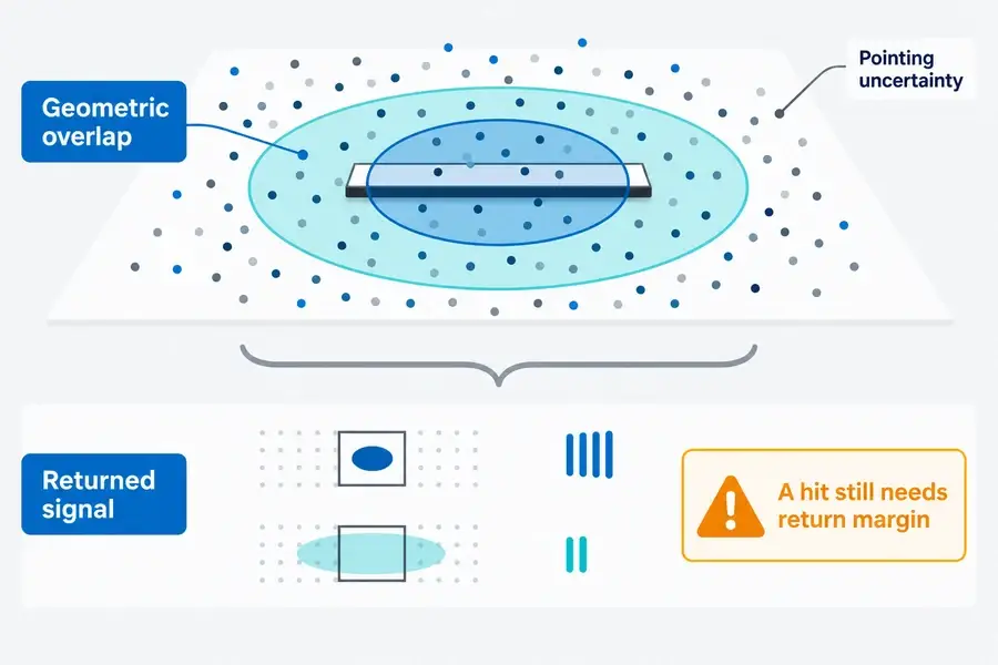
No reporte precisión solo para lecturas exitosas. Un sistema puede mantener un error ajustado en retornos aceptados mientras falla más a menudo. Registre retornos falsos y ausentes, además de la distribución de error de los resultados válidos.
Haces Más Estrechos y Más Anchos Resuelven Problemas Diferentes
Ninguna dirección es universalmente mejor. Los presupuestos dominantes de error y señal deciden.
| Preocupación de diseño | La divergencia más estrecha tiende a ayudar | La divergencia más ancha tiende a ayudar | Verifique antes de elegir |
|---|---|---|---|
| Largo alcance o retorno bajo | Mayor irradiancia en el objetivo cuando está alineado | — | Energía del pulso, intercepción del objetivo, atmósfera, sensibilidad del receptor |
| Característica pequeña cerca del fondo | Selectividad espacial | — | Estabilidad de alineación y perfil del haz |
| Vibración de apuntado o movimiento del objetivo | — | Tolerancia de superposición geométrica | Margen de retorno a través de la huella más grande |
| Objetivo pequeño con ubicación incierta | Can miss outside a tight footprint | Can cover more position uncertainty | Fraction of pulse actually intercepted |
| Multiple surfaces near an edge | Less background inclusion | — | Echo-selection and range-resolution behavior |
| Receiver acceptance | Does not set receiver FOV | Does not set receiver FOV | Transmit/receive boresight and angular tolerances |
The comparison assumes other variables stay constant, which is rare across modules. Divergence can change with exit optics, aperture, beam quality, temperature, assembly tolerances, or the optical window. Review the complete transmitter and receiver design.
For the source-versus-system boundary, see our descripción general de fuentes láser de medición. The page helps distinguish a laser-source parameter from the performance of a complete ranging module.
Partial Footprints Can Produce Weak or Mixed Returns
When the target is larger than the footprint and centered on it, nearly all incident energy can interact with that surface. If the target intercepts only part of the footprint, the remaining energy goes elsewhere. A dark foreground object in front of a bright wall may then generate a weaker return than the background even though the beam geometrically touches it.
If foreground and background are at different ranges, their contributions can overlap or form separate echoes depending on pulse width, range separation, receiver bandwidth, and processing. First, strongest, and last return rules can choose different surfaces. A single “beam hits target” statement cannot predict the reported distance.
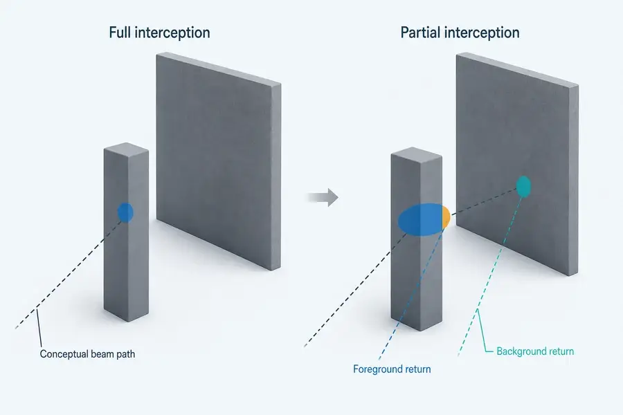
Peer-reviewed mixed-pixel studies use controlled foreground/background geometry to characterize this effect. A product-specific airborne LiDAR specification also conditions its target-detection statement on sufficient footprint interception. Those sources support the mechanism, not a transferable Lumexis performance number.
Divergence and Receiver Field of View Are Different
Transmit divergence defines where pulse energy is sent. Receiver field of view defines the angular region accepted by the receive optics and detector. They interact through boresight and alignment, but one does not substitute for the other.
A wide transmitter paired with a narrow or misaligned receiver can illuminate positions the receiver does not accept. Increasing receiver FOV may improve angular tolerance, but it can also admit more background and requires a complete signal-to-noise review. Aperture, filter bandwidth, detector area, focal length, and processing remain part of the result.
La types of laser rangefinder modules guide provides additional architecture context without treating one optical layout as universal.
What to Ask for in a Datasheet
Request more than a single mrad value:
- full-angle or half-angle convention;
- 1/e², FWHM, D4σ, encircled-energy, or another width definition;
- horizontal and vertical divergence with tolerance;
- exit diameter, waist/reference plane, and focus condition;
- operating temperature, drive condition, window, and lot/sample basis;
- transmitter-to-receiver boresight tolerance and receiver FOV;
- target size, reflectance, range, atmosphere, and footprint-interception condition;
- detection threshold, trial count, valid-range definition, and false/no-return treatment.
The best specification lets you reproduce the claim. A clean nominal value without tolerance or measurement definition is difficult to carry into an OEM error budget.
Validate Beam Divergence in the Installed System
Measure the final optical configuration, including its protective window and mount. Characterize the profile at several distances, then test several target sizes at the required reflectance and range.
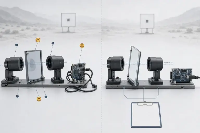
Apply controlled horizontal and vertical offsets that cover boresight error, vibration, motion, and assembly tolerance. Repeat enough pulses at each position to report valid, false, and absent returns. Add an edge case with a foreground target and background at a different range.
| Test group | Hold or record | Resultado |
|---|---|---|
| Geometría del haz | Distance, axis, width convention, temperature, window | Diameter/profile and centroid |
| Target overlap | Target size, reflectance, incidence, offset | Illumination coverage and return strength |
| System detection | Receiver FOV, mode, threshold, ambient condition | Valid, false, and no-return rates |
| Edge behavior | Foreground/background ranges and reflectances | Selected echo and distance error |
La páginas de solución de medición láser shows the civil and industrial system context. Lumexis y servicios de ingeniería can support module selection, integration, validation, and troubleshooting when the complete target and pointing envelope is available.
Qué enviar a Lumexis para la revisión del módulo
Share the range, target size and reflectance, required valid-detection probability, pointing-error distribution, laser rangefinder beam divergence convention and axes, receiver FOV, window, update rate, and environment.
Our applications engineers can review a standard módulo de telémetro láser estándar starting point or a custom/private-label requirement. Final hit probability still needs evidence from the installed optical and mechanical configuration.
Preguntas frecuentes
Is Lower Beam Divergence Always Better for a Rangefinder?
No. Lower divergence concentrates pulse energy and reduces the chance of including nearby surfaces, but it also tightens pointing and boresight requirements. A slightly wider beam can improve geometric overlap when motion or alignment uncertainty dominates. Choose against both target-return margin and the complete angular error budget.
How Large Is a 1 mrad Beam at 1 km?
Using a full-angle, small-angle estimate, 1 mrad adds about 1 m of beam diameter over 1 km. Add the initial beam diameter and confirm whether the supplier specifies full angle, half angle, 1/e², FWHM, or another definition. Real irradiance has no hard edge at the calculated diameter.
Should a Datasheet Quote Full-Angle or Half-Angle Divergence?
Either can be used if it is stated clearly. The problem is an unlabeled number. Ask for full versus half angle, width convention, both beam axes, tolerance, reference plane, and measurement condition. Convert all candidates to the same convention before comparing them.
Does Beam Divergence Change Distance Accuracy?
Divergence does not change light speed or the basic time-of-flight equation. It can change which surface contributes the accepted echo, the return amplitude, and the probability of receiving a valid result. Near edges or sloped surfaces, those effects can change the reported distance or increase invalid readings.
How Do Pointing Error and Beam Divergence Interact?
Pointing error shifts the beam center; divergence sets the footprint scale at range. A wider footprint can overlap a target across more pointing offsets, but each offset may intercept a different fraction of pulse energy. Validate their combined distribution rather than comparing one nominal pointing number with one nominal divergence number.
Send your target, range, pointing envelope, divergence definition, receiver FOV, window, and pass/fail criterion through the Lumexis contact page. We can identify a standard-module starting point or define the evidence needed for a custom configuration.
Referencias
- ISO. ISO 11146-1:2021 — Test Methods for Beam Widths, Divergence Angles and Beam Propagation Ratios
- RP Photonics Encyclopedia. Beam Radius
- Kruapech, S. and Widjaja, J. Laser Range Finder Using Gaussian Beam Range Equation
- Yang, P. et al. Laser Ranging Modeling Under Generalized Mixed Pixels Effect