








A small divergence value looks attractive on a datasheet. At long range, however, a tight beam can miss a narrow target when boresight error, platform motion, vibration, or target motion moves the footprint away from the intended point.
Making the beam wider is not a free fix. The same pulse energy is spread over a larger area, so less reaches a small target and more may illuminate foreground or background surfaces.
Laser rangefinder beam divergence sets how quickly the transmitted footprint grows with distance. Narrower divergence concentrates energy and improves spatial selectivity, but demands tighter pointing. Wider divergence increases geometric coverage, but lowers target irradiance and can mix returns. The best value depends on target size, pointing uncertainty, range, receiver field of view, and the required valid-detection probability.
What Laser Rangefinder Beam Divergence Actually Specifies
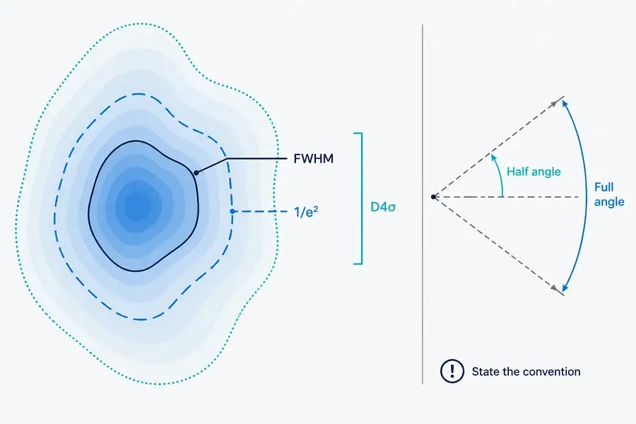
Beam divergence is an angular description of beam growth, commonly reported in milliradians. It is not a hard-edged cone. Real beams have an intensity distribution, and the quoted boundary depends on how beam width is defined.
For a Gaussian beam, the 1/e² radius is the point where intensity has fallen to about 13.5% of its on-axis value. Full width at half maximum (FWHM) describes a narrower part of that same profile. ISO 11146 uses a second-moment, or D4σ, approach for beam-width and propagation measurements. These values should not be compared as if they were interchangeable.
A complete specification states whether divergence is a full or half angle. An elliptical beam needs horizontal and vertical values. Ask what was measured, along which axes, under what condition, and from which reference plane.
Our guide to how a pulsed rangefinder measures distance explains the separate round-trip timing chain.
Convert Divergence into a Footprint at Range
For an initial beam diameter D₀, working distance L, and full-angle divergence Θ, a simple geometric estimate is:
D(L) = D₀ + 2L tan(Θ/2)
When the angle is small and expressed in radians, this becomes approximately D(L) ≈ D₀ + LΘ. One milliradian therefore adds about one meter of diameter per kilometer, before the initial diameter and other propagation effects are considered.
The estimate works only when the convention is clear. Using a half angle as a full angle creates a factor-of-two error in the growth term. Calculate both axes for an elliptical beam. An inclined target also sees an elongated footprint.
Do not treat the calculated diameter as a sharp boundary containing equal irradiance. Beam profile, truncation, optical-window effects, focus position, and beam quality change the energy distribution inside and outside the named contour. The rangefinder datasheet guide lists the conditions needed to interpret geometry alongside range claims.
Hit Probability Is Not the Same as Detection Probability
“Hit probability” is often used loosely. A useful engineering model separates at least three questions.
- Illumination probability: does enough of the transmitted footprint overlap the intended target, given pointing error and motion?
- Conditional detection probability: when the target is illuminated, does its return cross the receiver and processing criterion?
- Valid-range probability: does the system select the intended echo and report a distance inside the allowed error window?
A wider footprint can improve the first probability when pointing uncertainty dominates. It may reduce the second if only a small fraction of the pulse reaches the target. It can also reduce the third near edges when another surface contributes a stronger or earlier echo.
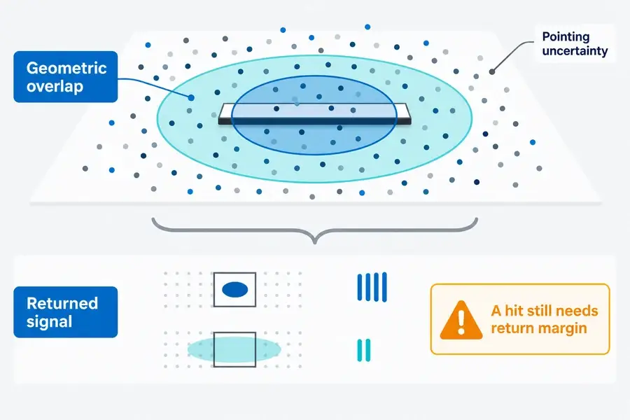
Do not report accuracy only for successful readings. A system can maintain tight error on accepted returns while missing more often. Record false and absent returns plus the error distribution of valid results.
Narrower and Wider Beams Solve Different Problems
Neither direction is universally better. The dominant error and signal budgets decide.
| Design concern | Narrower divergence tends to help | Wider divergence tends to help | Check before choosing |
|---|---|---|---|
| Long range or low return | Higher target irradiance when aligned | — | Pulse energy, target interception, atmosphere, receiver sensitivity |
| Small feature near background | Spatial selectivity | — | Boresight stability and beam profile |
| Pointing jitter or target motion | — | Geometric overlap tolerance | Return margin across the larger footprint |
| Small target with uncertain location | Can miss outside a tight footprint | Can cover more position uncertainty | Fraction of pulse actually intercepted |
| Multiple surfaces near an edge | Less background inclusion | — | Echo-selection and range-resolution behavior |
| Receiver acceptance | Does not set receiver FOV | Does not set receiver FOV | Transmit/receive boresight and angular tolerances |
The comparison assumes other variables stay constant, which is rare across modules. Divergence can change with exit optics, aperture, beam quality, temperature, assembly tolerances, or the optical window. Review the complete transmitter and receiver design.
For the source-versus-system boundary, see our Übersicht der Entfernungsmessungs-Laserquellen. The page helps distinguish a laser-source parameter from the performance of a complete ranging module.
Partial Footprints Can Produce Weak or Mixed Returns
When the target is larger than the footprint and centered on it, nearly all incident energy can interact with that surface. If the target intercepts only part of the footprint, the remaining energy goes elsewhere. A dark foreground object in front of a bright wall may then generate a weaker return than the background even though the beam geometrically touches it.
If foreground and background are at different ranges, their contributions can overlap or form separate echoes depending on pulse width, range separation, receiver bandwidth, and processing. First, strongest, and last return rules can choose different surfaces. A single “beam hits target” statement cannot predict the reported distance.
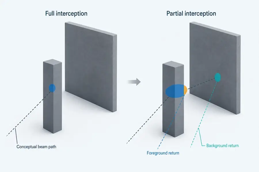
Peer-reviewed mixed-pixel studies use controlled foreground/background geometry to characterize this effect. A product-specific airborne LiDAR specification also conditions its target-detection statement on sufficient footprint interception. Those sources support the mechanism, not a transferable Lumexis performance number.
Divergence and Receiver Field of View Are Different
Transmit divergence defines where pulse energy is sent. Receiver field of view defines the angular region accepted by the receive optics and detector. They interact through boresight and alignment, but one does not substitute for the other.
A wide transmitter paired with a narrow or misaligned receiver can illuminate positions the receiver does not accept. Increasing receiver FOV may improve angular tolerance, but it can also admit more background and requires a complete signal-to-noise review. Aperture, filter bandwidth, detector area, focal length, and processing remain part of the result.
Der types of laser rangefinder modules guide provides additional architecture context without treating one optical layout as universal.
What to Ask for in a Datasheet
Request more than a single mrad value:
- full-angle or half-angle convention;
- 1/e², FWHM, D4σ, encircled-energy, or another width definition;
- horizontal and vertical divergence with tolerance;
- exit diameter, waist/reference plane, and focus condition;
- operating temperature, drive condition, window, and lot/sample basis;
- transmitter-to-receiver boresight tolerance and receiver FOV;
- target size, reflectance, range, atmosphere, and footprint-interception condition;
- detection threshold, trial count, valid-range definition, and false/no-return treatment.
The best specification lets you reproduce the claim. A clean nominal value without tolerance or measurement definition is difficult to carry into an OEM error budget.
Validate Beam Divergence in the Installed System
Measure the final optical configuration, including its protective window and mount. Characterize the profile at several distances, then test several target sizes at the required reflectance and range.
Apply controlled horizontal and vertical offsets that cover boresight error, vibration, motion, and assembly tolerance. Repeat enough pulses at each position to report valid, false, and absent returns. Add an edge case with a foreground target and background at a different range.
| Test group | Hold or record | Outcome |
|---|---|---|
| Beam geometry | Distance, axis, width convention, temperature, window | Diameter/profile and centroid |
| Target overlap | Target size, reflectance, incidence, offset | Illumination coverage and return strength |
| System detection | Receiver FOV, mode, threshold, ambient condition | Valid, false, and no-return rates |
| Edge behavior | Foreground/background ranges and reflectances | Selected echo and distance error |
Der laser-ranging solution shows the civil and industrial system context. Lumexis Engineering-Dienstleistungen can support module selection, integration, validation, and troubleshooting when the complete target and pointing envelope is available.
What to Send Lumexis for Module Review
Share the range, target size and reflectance, required valid-detection probability, pointing-error distribution, laser rangefinder beam divergence convention and axes, receiver FOV, window, update rate, and environment.
Our applications engineers can review a standard Laser-Entfernungsmessermodul starting point or a custom/private-label requirement. Final hit probability still needs evidence from the installed optical and mechanical configuration.
Häufig gestellte Fragen
Is Lower Beam Divergence Always Better for a Rangefinder?
No. Lower divergence concentrates pulse energy and reduces the chance of including nearby surfaces, but it also tightens pointing and boresight requirements. A slightly wider beam can improve geometric overlap when motion or alignment uncertainty dominates. Choose against both target-return margin and the complete angular error budget.
How Large Is a 1 mrad Beam at 1 km?
Using a full-angle, small-angle estimate, 1 mrad adds about 1 m of beam diameter over 1 km. Add the initial beam diameter and confirm whether the supplier specifies full angle, half angle, 1/e², FWHM, or another definition. Real irradiance has no hard edge at the calculated diameter.
Should a Datasheet Quote Full-Angle or Half-Angle Divergence?
Either can be used if it is stated clearly. The problem is an unlabeled number. Ask for full versus half angle, width convention, both beam axes, tolerance, reference plane, and measurement condition. Convert all candidates to the same convention before comparing them.
Does Beam Divergence Change Distance Accuracy?
Divergence does not change light speed or the basic time-of-flight equation. It can change which surface contributes the accepted echo, the return amplitude, and the probability of receiving a valid result. Near edges or sloped surfaces, those effects can change the reported distance or increase invalid readings.
How Do Pointing Error and Beam Divergence Interact?
Pointing error shifts the beam center; divergence sets the footprint scale at range. A wider footprint can overlap a target across more pointing offsets, but each offset may intercept a different fraction of pulse energy. Validate their combined distribution rather than comparing one nominal pointing number with one nominal divergence number.
Send your target, range, pointing envelope, divergence definition, receiver FOV, window, and pass/fail criterion through the Lumexis contact page. We can identify a standard-module starting point or define the evidence needed for a custom configuration.
Referenzen
- ISO. ISO 11146-1:2021 — Test Methods for Beam Widths, Divergence Angles and Beam Propagation Ratios
- RP Photonics Encyclopedia. Beam Radius
- Kruapech, S. and Widjaja, J. Laser Range Finder Using Gaussian Beam Range Equation
- Yang, P. et al. Laser Ranging Modeling Under Generalized Mixed Pixels Effect