
Ranging laser sources
Ranging Laser Sources: Build Around the Range Budget
Lumexis develops compact 1535 nm Er:glass laser sources for pulsed Time-of-Flight ranging, with source configurations selected around the target, working distance, optics, timing, receiver, and OEM integration limits.
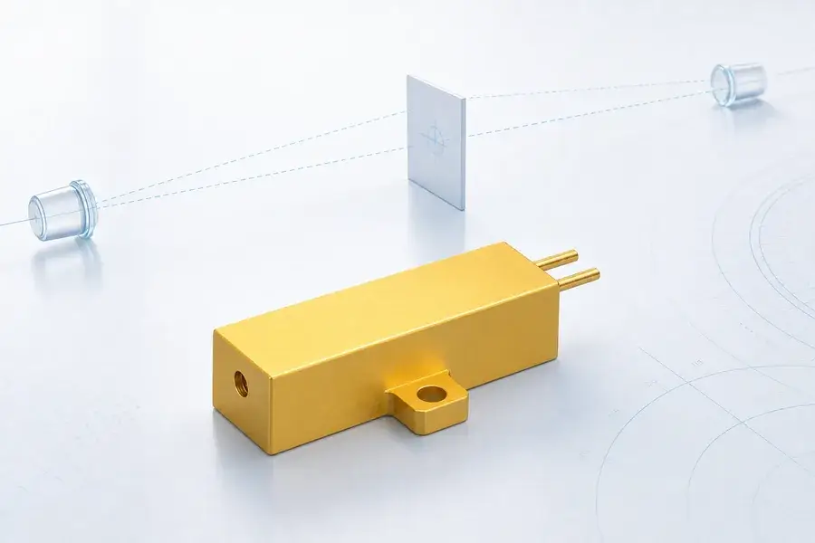
Build the transmitter around the required range budget—not pulse energy alone.
Lumexis develops and manufactures compact 1535 nm Er:glass laser sources for pulsed Time-of-Flight (ToF) ranging. The portfolio spans 40 to 500 µJ, 3–6 ns pulse width, and configurations from 1–10 Hz up to 1000 Hz, giving instrument teams a practical starting point for compact ranging, camera-assisted measurement, field instruments, scientific measurement, and OEM optical subsystems.
A 1535 nm laser source for laser ranging should be selected as one part of the transmitter-to-receiver link. This page therefore begins with application fit and exact source parameters, then connects those values to optics, timing, detection, and integration decisions.
To match a source quickly, send us six inputs:
- target material, size, angle, and expected reflectivity;
- normal and maximum working distance;
- required measurement or update rate;
- transmit-aperture and final beam-divergence limits;
- source envelope, mass, voltage, and temperature limits;
- receiver aperture, detector type, and timing architecture.
Fastest route: Send your range budget and integration limits for a source recommendation.
Start with the ranging application
Application fit
Match the optical source to the real measurement task
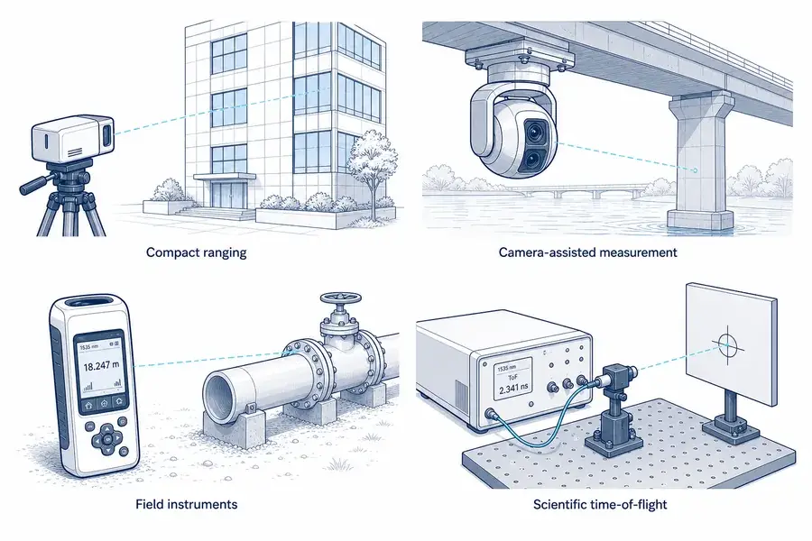
Four applications for 1535 nm ranging laser sources: compact ranging, camera-assisted measurement, field instruments, and scientific time-of-flight systems.
| Application | What the 1535 nm source contributes | What the finished system must add | Start the RFQ with |
|---|---|---|---|
| Compact optical rangefinders | A short optical pulse for direct ToF measurement | source driver, transmit optics, receiver, timing electronics, enclosure, interface | distance envelope, target, aperture, rate, package |
| Camera-assisted civil measurement | A range channel along a calibrated line of sight | camera-to-laser alignment, target selection, pose or pointing data, host processing | camera field of view, boresight, target size, latency |
| Handheld and field instruments | Compact pulsed emission for surveying, asset inspection, and scientific field measurements | user interface, power management, aiming method, receiver, calibration | update rate, operating temperature, battery budget, closest distance |
| Scientific ToF instruments | A controlled nanosecond pulse for timing experiments and remote measurements | trigger definition, emission reference, detector chain, data acquisition, uncertainty analysis | timing reference, repetition rate, detector bandwidth, logging |
| OEM optical subsystems | A source building block that can be packaged around project-specific optics and electronics | mechanical datum, thermal path, electrical drive, optical isolation, qualification | volume envelope, mounting, voltage, lifetime profile, test plan |
What this product is—and what it is not
The Er:glass laser source is the emitter inside a ranging transmitter. It creates the optical pulse, but it does not by itself calculate distance or provide a complete ranging channel.
A working rangefinder also requires:
- a compatible pump and drive circuit;
- trigger control and a defined emission-time reference;
- collimation or beam-expansion optics;
- a target path and suitable external window;
- receive optics and spectral filtering;
- an InGaAs detector and low-noise receiver chain;
- timing, detection, validation, and host-interface electronics.
This distinction matters in procurement. A source data sheet should be compared with other sources. A complete rangefinder should be compared by target-conditioned range, minimum range, accuracy, valid-measurement behavior, interface, package, and environmental performance.
Match the Lumexis source platform
The table below is an initial selection guide. Values are nominal product-platform specifications; confirm the order-specific drawing, operating conditions, and acceptance criteria before mechanical or electrical release.
| Model | Wavelength | Pulse energy | Repetition rate | Pulse width | Source divergence | Supply voltage | Operating temperature | Mass |
|---|---|---|---|---|---|---|---|---|
| 1535-LXER040 | 1535 nm | 40 µJ | 1000 Hz | 3–6 ns | ≤15 mrad | <2 V | −40 to +65 °C | Confirm by configuration |
| 1535-LXER100 | 1535 nm | 100 µJ | 1–10 Hz | 3–6 ns | ≤10 mrad | <2 V | −40 to +65 °C | 9 g |
| 1535-LXER200 | 1535 nm | 200 µJ | 1–10 Hz | 3–6 ns | ≤10 mrad | <2 V | −40 to +65 °C | 9 g |
| 1535-LXER300 | 1535 nm | 300 µJ | 1–10 Hz | 3–6 ns | ≤10 mrad | <2 V | −40 to +65 °C | 9 g |
| 1535-LXER400 | 1535 nm | 400 µJ | 1–10 Hz | 3–6 ns | ≤15 mrad | <2 V | −40 to +65 °C | 11 g |
| 1535-LXER500 | 1535 nm | 500 µJ | 1–10 Hz | 3–6 ns | ≤15 mrad | <2 V | −40 to +65 °C | 13 g |
Practical selection logic
Start with 1535-LXER040 when the application values a high source repetition rate and the system can close its range budget with 40 µJ pulses. At 1000 Hz, this platform is suited to higher-rate sampling architectures, scanning experiments, or systems that need more frequent opportunities to acquire a return.
Start with 1535-LXER100, 200, or 300 when the instrument needs more energy per pulse at a low measurement rate. These three options share a 1–10 Hz rate class, 3–6 ns pulse width, ≤10 mrad source divergence, and a listed mass of 9 g, making pulse energy the first differentiator within this group.
Consider 1535-LXER400 or 500 when the link budget needs a higher transmitted-energy class and the package can accept the corresponding 11 g or 13 g source. Higher energy can add return margin, but it does not guarantee a specific distance. Transmit optics, target fill, atmosphere, receiver aperture, detector performance, background, and detection logic remain part of the result.
Do not select by pulse energy alone
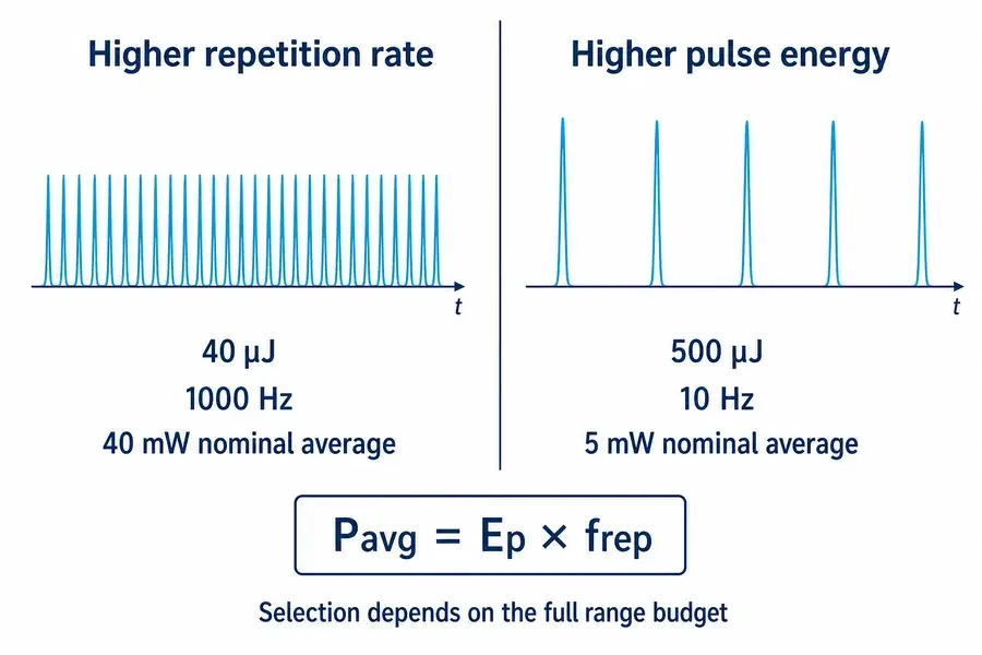
Two sources can have very different intended operating points even when both are suitable for ranging. The 40 µJ platform provides a much higher pulse rate; the 500 µJ platform provides more energy in each pulse but at a lower repetition rate. Those choices affect sample opportunity, peak signal, average optical power, driver behavior, thermal design, detector recovery, and system-level validation.
Parameter interaction
Evaluate coupled parameters at the operating point
Comparison of a 40 µJ, 1000 Hz source and a 500 µJ, 10 Hz source, illustrating repetition-rate and pulse-energy tradeoffs.
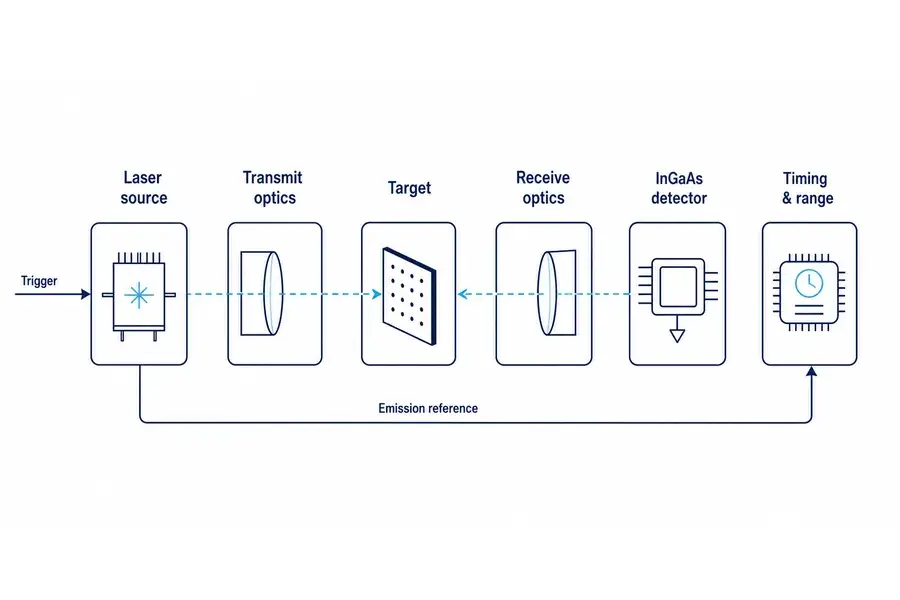
Where the source fits in a Time-of-Flight rangefinder
System architecture
Review the complete optical and measurement chain
System architecture from a 1535 nm laser source through transmit optics, target, receive optics, InGaAs detector, and timing electronics.
A direct-ToF instrument measures the interval between an emitted pulse and a detected return. In the simplest form, the one-way distance is:
R = cΔt / 2
where R is one-way distance, c is the propagation speed of light, and Δ t is the measured round-trip interval. The factor of two accounts for the outbound and return paths. NASA’s laser-altimetry explanation applies the same round-trip relationship: optical travel distance is calculated from light speed and elapsed time, then divided by two for one-way range.1
The source participates in three timing events:
- Command or trigger: the drive electronics initiate a pulse cycle.
- Optical emission: the pulse actually leaves the source. This event may not be identical to the command edge because driver and build-up delays can vary.
- Return detection: the receiver identifies a target return and generates a timing event.
For precision timing, define what starts the clock. A command edge is convenient, but an emission monitor or characterized emission delay may provide a better reference. The right approach depends on the required ranging uncertainty, driver design, temperature behavior, repetition mode, and calibration strategy.
The receiver must match the wavelength and pulse
At 1535 nm, the receiver commonly uses an InGaAs detector rather than a silicon detector. Commercial InGaAs avalanche photodiodes are available with sensitivity covering the 1.5 µm region and are promoted specifically for distance-measurement and LiDAR receiver applications.2
Detector choice is not only a wavelength decision. The engineering team must also define:
- active area and optical field of view;
- responsivity or detection efficiency at the operating wavelength;
- gain, bandwidth, noise, and temperature behavior;
- saturation and recovery after strong near returns;
- background-light filtering;
- thresholding, constant-fraction, correlation, or other timing method;
- false-alarm and valid-detection criteria.
A stronger optical pulse may help the return signal, but it can also make close targets, internal reflections, and receiver recovery more demanding. Transmitter and receiver should therefore be reviewed together.
How to read the source parameters
Pulse energy: useful energy delivered in one event
Pulse energy E_p, expressed in microjoules, is the optical energy in a single pulse. In an otherwise unchanged system, more transmitted energy can increase the energy available for a target return. In a real instrument, “otherwise unchanged” rarely holds: package, drive conditions, repetition rate, divergence, optics, detector dynamic range, and operating life may also change.
Pulse energy is not a distance rating. The receiver sees only a small fraction of the emitted pulse after beam spreading, target interaction, atmospheric loss, collection loss, filtering, and detector conversion.
Pulse width: a nanosecond-scale timing input
Lumexis Er:glass source platforms list a 3–6 ns pulse-width range. Short pulses support direct-ToF timing because the returned waveform can be localized in time, but pulse width is only one contributor to distance precision. Detector bandwidth, signal-to-noise ratio, timing threshold, pulse shape, target depth, sampling method, and calibration can broaden or shift the measured event.
The approximate spatial length of a pulse in free space is cτ, but the one-way range interval corresponding to a round-trip duration is cτ/2. That does not mean a 6 ns pulse automatically produces a fixed accuracy of cτ/2. Estimation electronics can locate an event within a waveform, while noise and target structure can move the apparent timing point. Use measured system accuracy and repeatability—not pulse width alone—for acceptance.
Peak power: an estimate that requires a pulse-shape assumption
For a rectangular-pulse approximation:
Ppeak ≈ Ep / τp
A nominal 100 µJ pulse over 3–6 ns corresponds to an average power during that idealized pulse interval of approximately 17–33 kW. A nominal 500 µJ pulse gives approximately 83–167 kW by the same arithmetic. These are explanatory estimates, not guaranteed product values: actual peak power depends on the measured temporal pulse shape and the definition used for pulse width.
Peak power is important to return-signal formation and optical-component review. It is not the same as average optical power, electrical input power, or host-supply peak demand.
Repetition rate: measurement opportunity, not guaranteed output rate
Repetition rate describes how often the source can emit under the specified operating mode. A 1000 Hz optical pulse rate can support frequent sampling, but the finished instrument may output fewer valid ranges because of receiver gating, target loss, processing, filtering, communication, or scanning geometry. Likewise, a 10 Hz source does not guarantee ten accepted distance values per second.
Define four separate rates in the system specification:
- commanded trigger rate;
- confirmed optical emission rate;
- receiver acquisition rate;
- valid range-output rate.
Keeping these terms separate prevents a common integration error: treating a source repetition number as the complete instrument’s guaranteed data rate.
Average optical power: pulse energy multiplied by rate
For a repetitive pulsed source:
Pavg = Epfrep
This relationship explains why a lower-energy, high-rate source can have more average optical output than a higher-energy, low-rate source. It does not provide the source’s electrical efficiency or the peak current required from its driver. Ask separately for driver input, pulse-current behavior, duty cycle, startup sequence, and thermal path.
Source divergence: an input to the transmit optics
The listed ≤10 or ≤15 mrad value describes the source output, not necessarily the final beam leaving the instrument. A complete rangefinder normally adds collimation or beam-expansion optics to set the output diameter, divergence, wavefront, and optical axis.
Optical delivery
Balance power, beam delivery, and target geometry
Optical integration diagram showing raw 10–15 mrad source divergence, collimation optics, and the final system transmit beam.
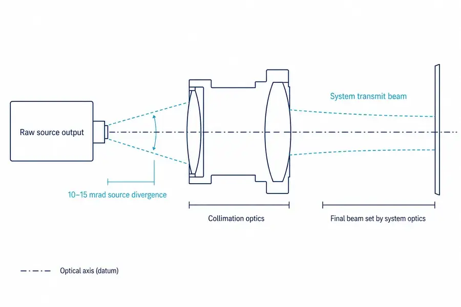
For a far-field estimate using full-angle divergence:
d ≈ Rθ
where d is the approximate beam diameter on the target, R is distance, and θ is full-angle divergence in radians. This simple relationship is useful for target-fill thinking, but initial beam diameter, beam profile, focus, aberration, turbulence, and pointing motion can also matter.
A narrower final beam can place more energy on a small distant target. It also requires tighter boresight, pointing, vibration, and thermal-drift control. The transmit axis must remain inside the receiver field of view and on the intended target throughout operation.
Why wavelength alone does not determine system performance
The 1535 nm band is useful for compact Er:glass pulsed sources and is compatible with established InGaAs receiver technology. It also supports a different laser-safety design space from shorter near-infrared wavelengths because tissue absorption and applicable exposure limits vary with wavelength.
However, no wavelength label establishes the classification of a finished product. Classification depends on accessible emission, pulse energy, pulse duration, repetition pattern, aperture, divergence, exposure geometry, measurement method, and the completed optical assembly. Lumexis will define any formal classification or compliance statement only for a documented finished configuration.
Wavelength also does not remove environmental limits. Fog, rain, dust, aerosols, heat shimmer, condensation, and a dirty external window can reduce usable return or create unwanted near backscatter. Test the assembled transmitter and receiver through the final window under representative conditions.
The range budget: translate the application into source requirements
For a diffuse target, a simplified directional relationship can be written as:
psurface = psensor + Rulook
where:
- E_r is received pulse energy;
- E_t is transmitted pulse energy;
- ηtx and ηrx represent transmit- and receive-path efficiency;
- T^2 represents two-way atmospheric transmission;
- Ftarget represents the useful fraction of the beam footprint on the target;
- ρ is an effective target-return term for the chosen model;
- A_r is receiver-aperture area;
- R is range.
This is an educational proportional relationship, not a universal acceptance equation. Exact link models depend on whether the target fills the beam, target geometry and scattering, beam profile, receiver field of view, background, detection statistics, and system architecture. Published ICESat/GLAS return-energy analysis likewise links transmitted pulse energy, receiver area, range, surface response, and two-way atmospheric transmission.3
Eight range-budget questions that improve a source recommendation
1. What is the target?
Give dimensions, material, finish, color only as supporting context, expected reflectivity at the operating wavelength if known, and the range of incidence angles. A large diffuse wall and a narrow edge are not equivalent targets.
2. Does the target fill the beam footprint?
If the beam footprint overfills the target, only part of the transmitted energy interacts usefully. A higher-energy source may not compensate efficiently for poor pointing or an oversized final beam.
3. What is the normal range, not only the maximum?
The normal working distance often determines the best source. A system designed only around an extreme maximum can create excessive near-return signal, unnecessary size, lower rate, higher cost, or more difficult validation.
4. What atmosphere and window are realistic?
Specify visibility, humidity, dust, rain, fog, operating altitude, external-window material, coatings, incidence angle, and contamination plan. Loss applies on the outgoing and return paths.
5. What receive aperture is available?
For a circular aperture, collection area is A_r=π D^2/4. Increasing diameter can improve collection, but it also affects envelope, mass, window size, field of view, alignment, and cost.
6. What detector and threshold will be used?
Receiver noise and background establish how much return is needed for a defined probability of detection and false-alarm level. “Detectable” must be connected to an acceptance criterion.
7. How stable is the line of sight?
Include pointing error, vibration, mechanical tolerance, boresight drift, optical-axis shift, and any scanner or camera alignment error. Narrower divergence only helps if the system consistently illuminates the intended target.
8. What valid-measurement behavior is required?
Define missed returns, false returns, multi-surface scenes, first/strongest/last-return logic, gating, timeout, and invalid-data reporting. The source creates pulses; the complete ranging system decides which return becomes a distance.
Integration checklist for OEM engineering teams
Electrical drive and trigger
- Confirm the exact source configuration and compatible driver before applying power.
- Define supply limits at the source pins under transient conditions, not only at the bench supply.
- Document trigger level, edge, pulse duration, allowable rate, inhibit behavior, and startup sequence.
- Separate the optical-emission reference from the command trigger when the uncertainty budget requires it.
- Review grounding, cable impedance, electromagnetic coupling, and receiver isolation in the complete enclosure.
Mechanical mounting
- Use the approved mounting datum and fastener limits from the order-specific drawing.
- Avoid chassis stress that can alter alignment or damage the source package.
- Define the optical-axis location and angular tolerance relative to the host datum.
- Reserve adjustment or calibration authority if the production tolerance stack cannot hold boresight directly.
- Verify mass-property and vibration requirements on the assembled instrument.
Optical train
- Select collimator focal length, clear aperture, coating, and working distance for the real source output.
- Check beam clipping across tolerance and temperature.
- Control feedback and internal reflections from lenses, filters, and the external window.
- Keep transmit leakage out of the receiver or define recovery and gating around it.
- Measure final divergence and boresight after enclosure assembly, not only on the optical bench.
Thermal and environmental design
The platform operating-temperature range is −40 to +65 °C, but finished-system performance still depends on the driver, mounting, enclosure, optics, detector, and calibration. A source operating within temperature limits does not guarantee constant pulse energy, timing, alignment, or range for the complete instrument.
Build the qualification plan around:
- cold start and hot start;
- pulse energy and emission delay over temperature;
- high- and low-rate duty profiles;
- optical-axis drift;
- window condensation and contamination;
- vibration before and after alignment;
- receiver noise and detection threshold over temperature;
- repeated cycling and acceptance limits.
Production and acceptance
Convert system intent into measurements that can be repeated:
- pulse energy and measurement method;
- pulse width definition and instrument bandwidth;
- center wavelength and spectral method;
- repetition mode and duty profile;
- source divergence definition and measurement plane;
- optical-axis datum and allowed error;
- electrical test conditions;
- environmental state and stabilization time;
- traceability, sampling plan, and pass/fail limits.
The more precisely these items are defined before prototype release, the easier it is to compare samples, control integration changes, and scale production.
What to include in your RFQ
| Category | Information to provide | Why Lumexis needs it |
|---|---|---|
| Application | compact ranging, camera-assisted measurement, field instrument, scientific ToF, or OEM subsystem | establishes the operating pattern and integration boundary |
| Target | size, material, return behavior, incidence angle, background | determines useful return and detection challenge |
| Distance | minimum, normal, maximum, and required margin | prevents selection around one headline number |
| Rate | trigger, emission, acquisition, and valid-output targets | separates source rate from system data rate |
| Transmit optics | aperture, final divergence, beam diameter, window | connects source divergence to target fill and alignment |
| Receiver | aperture, field of view, InGaAs device, filter, bandwidth | completes the range budget |
| Timing | trigger definition, emission reference, precision, latency | defines the distance-measurement chain |
| Mechanical | available envelope, mounting datum, mass limit, optical axis | identifies packaging and alignment constraints |
| Electrical | source voltage, driver approach, control interface, duty cycle | supports compatible source and driver integration |
| Environment | temperature, vibration, humidity, contamination, visibility | defines validation conditions |
| Qualification | prototype quantity, test plan, acceptance limits, production forecast | aligns development samples with scalable supply |
Frequently asked questions
Is a 1535 nm Er:glass laser source a complete laser rangefinder?
No. It is the pulsed emitter used in the transmitter. A complete rangefinder also needs drive electronics, transmit optics, a receiver, detector, timing and detection electronics, mechanical alignment, an external optical path, and a host interface.
Which pulse energy should I choose for long-distance ranging?
Choose from a range budget, not distance alone. Higher pulse energy can add transmitter margin, but target fill, atmospheric transmission, receive aperture, detector sensitivity, background, timing method, and acceptable detection probability can be equally decisive. Send those inputs for a meaningful recommendation.
Is 40 µJ at 1000 Hz weaker than 500 µJ at 10 Hz?
It is not a useful one-word comparison. The 500 µJ source delivers more energy per pulse, which may support a stronger individual return. The 40 µJ source emits more frequently and has a higher nominal average optical output at the listed maximum rate. The right choice depends on acquisition rate, target return, detector behavior, power, thermal design, and scanning or sampling method.
Does the listed 10–15 mrad divergence equal the rangefinder’s final beam divergence?
Not necessarily. It is the source-output specification. The finished transmitter normally uses collimation or beam-expansion optics to establish the final beam diameter and divergence. Final performance must be measured after the optical and mechanical assembly is aligned.
Can pulse width be converted directly into distance accuracy?
No. Pulse width is part of the timing problem, but accuracy also depends on waveform shape, detector and electronics bandwidth, signal-to-noise ratio, timing threshold, calibration, target depth, and environmental conditions. Use measured system accuracy under stated test conditions.
Can Lumexis customize the source for an OEM instrument?
Lumexis can review project-specific requirements for optical output, repetition mode, package integration, mounting, drive compatibility, environmental use, testing, and production supply. Feasibility and final specifications are confirmed through engineering review.
What receiver technology is commonly used at 1535 nm?
InGaAs photodiodes and avalanche photodiodes are widely used in the 1.5 µm region. Detector selection should also account for active area, gain, bandwidth, noise, background light, temperature, saturation, and timing method.2
What data should be collected during prototype tests?
Record the source configuration, pulse energy, pulse width, repetition mode, emission reference, target, distance, target angle, atmosphere, transmit optics, receiver settings, temperature, supply behavior, raw detection state, and valid-range output. This makes failures diagnosable and comparisons repeatable.
Request a source recommendation
Send Lumexis your application, target, distance envelope, required rate, transmit aperture, final divergence, receiver concept, size and mass limits, temperature range, prototype quantity, and schedule. Our engineers will help map the project to the 40–500 µJ platform and identify the optical, timing, and qualification questions that must be closed before production.
Suggested CTA: Request a 1535 nm ranging laser source recommendation.
Secondary CTA: Share your range budget for engineering review.
Lumexis — precision laser sources, engineered for the real world.
Technical references
Additional technical background consulted
- G. J. Spühler et al., “Experimentally confirmed design guidelines for passively Q-switched microchip lasers using semiconductor saturable absorbers,” provides general pulse-generation background; it does not document the internal construction of Lumexis products. Optica article record
- R. Häring et al., “Passively Q-switched microchip laser at 1.5 µm,” provides peer-reviewed background on compact pulsed emitters in this wavelength region; Lumexis does not infer an identical architecture from this source. Optica article record
NASA Goddard Space Flight Center, The Geoscience Laser Altimeter System: How laser altimetry measures distance. Educational technical overview ↩
Hamamatsu Photonics, InGaAs APDs for distance measurement and LiDAR applications. Product and technical overview ↩↩
NASA/ICESat research, ICESat/GLAS Altimetry Measurements: Received Signal Dynamic Range and Saturation Correction. Open-access paper ↩