



La mayoría de los problemas láser que aparecen tarde en un programa se remontan a la bomba, no al resonador. La salida se desvía a medida que la placa base se calienta. La eficiencia parece buena en el banco y desaparece a −30 °C. Un diseño que cumplía las especificaciones con un lote de diodos no las cumple con el siguiente.
El resonador suele acaparar la atención porque es donde la física resulta interesante. La bomba es donde viven el calor, la deriva y los modos de fallo.
Este artículo explica qué hace realmente el bombeo láser, en qué se diferencian las principales arquitecturas de bombeo y qué decisiones sobre la fuente de bombeo determinan si un láser mantiene sus especificaciones a lo largo de la temperatura, el tiempo y el volumen de producción.
Tabla de Contenidos
LUMEXIS
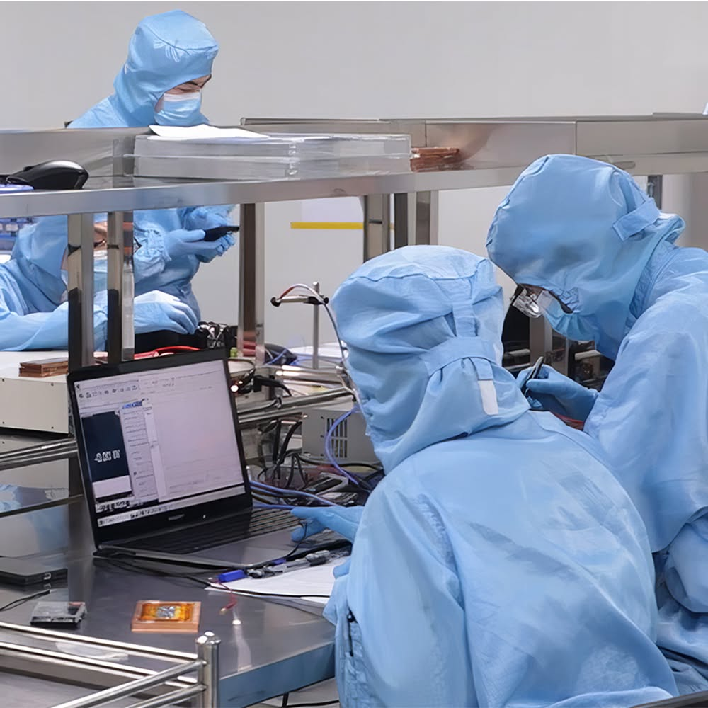
Sala limpia para el ensamblaje de módulos láser
El bombeo láser es el proceso de inyectar energía en un medio de ganancia para crear inversión de población — más átomos en un estado excitado que en el estado inferior — de modo que la emisión estimulada pueda producir ganancia óptica. La energía se entrega ópticamente (diodos, lámparas de destello), eléctricamente (corriente a través de un semiconductor o gas) o químicamente. Sin bombeo, no hay láser.
La física, en la cantidad de detalle que realmente importa
En equilibrio térmico, casi todos los átomos de un material se encuentran en su estado fundamental. Si se hace pasar luz a través de él, la luz se absorbe. Eso es normal, y es lo contrario de lo que necesita un láser.
El bombeo invierte eso. La energía empuja los átomos hacia un estado excitado más rápido de lo que decaen, hasta que hay más excitados que no excitados. Una vez que existe esa inversión, un fotón entrante de la energía adecuada tiene más probabilidades de estimular a un átomo excitado para que emita un fotón idéntico que de ser absorbido. La luz que entra en el medio sale amplificada. Eso es la ganancia óptica, y todo lo demás en un láser — espejos, Q-switch, acoplador de salida — es maquinaria construida en torno a ella.
Dos detalles estructurales gobiernan lo difícil que es lograr la inversión.
A de cuatro niveles el medio de ganancia hace caer el átomo a un nivel láser inferior que está esencialmente vacío a temperatura ambiente, y luego lo vuelca rápidamente al estado fundamental. Como el nivel inferior permanece vacío, la inversión ocurre en cuanto se excita una pequeña fracción de los iones. Nd:YAG a 1064 nm funciona así, lo cual es gran parte de por qué es tan tolerante.
A cuasi-tres-niveles el medio tiene un nivel láser inferior que está térmicamente poblado. Estás luchando contra la reabsorción de tu propia salida, así que una fracción sustancial de los iones debe excitarse antes de que veas alguna ganancia neta. Los sistemas de iterbio y erbio suelen comportarse así. Exigen mayor intensidad de bombeo y una gestión térmica mucho más estricta, y castigan una fuente de bombeo subespecificada mucho más de lo que lo hace un diseño de cuatro niveles.
Vale la pena llevar esta distinción a una revisión de diseño, porque determina cuánto margen de bombeo necesitas antes de que el láser arranque siquiera en el extremo frío de tu rango de operación.
Entre esos dos se sitúa el clásico sistema de tres niveles, que vale la pena conocer porque es donde comenzó el campo. En el rubí, una lámpara de destello eleva los iones de cromo a una banda de absorción amplia, desde la cual caen de forma no radiativa a un nivel metaestable en aproximadamente 10−8 s. Ese nivel luego los retiene durante unos 10−3 s — cinco órdenes de magnitud más — así que la población se acumula allí hasta que supera el estado fundamental y la salida a 694,3 nm se vuelve posible. La relación entre esas dos escalas de tiempo es todo el truco, y reaparece más adelante en este artículo como lo que decide cuánta energía puede almacenar un láser Q-switched.
Una fuente de bombeo es un sistema, no un componente
Los ingenieros especifican una bomba como una longitud de onda y una potencia. Los proveedores envían un ensamblaje. Entre esas dos afirmaciones se sitúan cuatro subsistemas, y cualquiera de ellos puede ser lo que silenciosamente te cueste un diez por ciento de tu salida.
La electrónica de accionamiento. La longitud de onda, la potencia de salida y la vida útil de un diodo siguen su corriente de unión y su temperatura. Un driver con mala regulación de corriente, rizado visible o un encendido no controlado desplaza la longitud de onda de emisión durante el pulso y acorta la vida del diodo a través de transitorios. En operación cuasi-continua, el tiempo de subida de la corriente da forma directamente al pulso de bombeo y por lo tanto a la energía almacenada. El driver no es un accesorio de la fuente de bombeo. Es parte de ella.
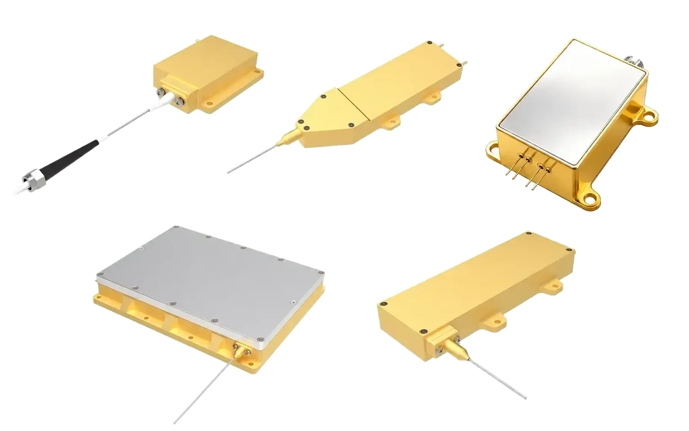
El emisor. Emisor único, barra o pila — y, dentro de un módulo acoplado a fibra, la óptica de conformación de haz que convierte una salida de diodo salvajemente asimétrica en algo que una fibra realmente aceptará.
La ruta de acoplamiento. Colimación de eje rápido, colimación de eje lento, enfoque, a veces multiplexación de polarización y longitud de onda, y la propia fibra. Cada superficie aquí conlleva una pérdida de transmisión y un coeficiente térmico.
La ruta térmica. Submount, solder, baseplate, interface material, cold plate. Junction temperature is what the physics responds to; case temperature is what the datasheet quotes. The difference between them is a property of this stack, not of the diode.
Una disciplina útil en una revisión de diseño es preguntar cuál de estos cuatro estás comprando y cuál se te deja para que lo construyas. Un diodo desnudo es barato porque tres de los cuatro se convierten en tu problema. Un módulo acoplado a fibra caracterizado cuesta más porque el proveedor ya ha cerrado el ciclo en los cuatro y puede declarar la potencia entregada en el extremo de la fibra a lo largo de tu ventana de temperatura.
Bombeo óptico, eléctrico, químico – Cuál es la diferencia
Hay tres formas de entregar energía de bombeo, y en la práctica la mayoría de los ingenieros solo se encuentran con dos.
Bombeo óptico utiliza luz adaptada a las bandas de absorción del medio de ganancia. Las lámparas de destello hicieron esto durante décadas y todavía aparecen en sistemas pulsados de alta energía, pero son de banda ancha, ineficientes y calientes: la mayor parte de la salida de la lámpara cae fuera de la banda de absorción y se convierte en calor residual en el cristal. Los diodos láser los reemplazaron en casi todas partes porque la emisión de diodo puede colocarse directamente sobre un pico de absorción. Ese único cambio — la adaptación espectral — es responsable de la mayor parte de la ganancia de eficiencia en los láseres de estado sólido durante los últimos treinta años.
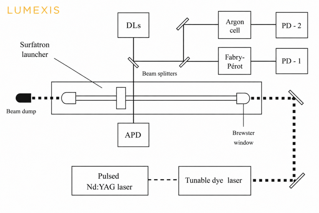
Bombeo eléctrico impulsa corriente directamente a través del medio de ganancia. Los láseres de gas utilizan una descarga. Los láseres de diodo semiconductor utilizan corriente a través de una unión p-n, donde la recombinación produce fotones directamente. Los láseres de diodo son dispositivos bombeados eléctricamente que a su vez se utilizan como bombas ópticas para otros láseres, lo cual es algo genuinamente útil de tener claro.
Bombeo químico extrae la inversión de una reacción, típicamente la combustión de hidrógeno y flúor. Escala a potencias muy altas sin suministro eléctrico, que es la razón por la que existe, pero es raro y está confinado a sistemas especializados.
Para cualquier cosa que probablemente diseñes en un producto, la cuestión no es cuál de los tres usar. Es qué diodo de bombeo, a qué longitud de onda, en qué geometría.
Pon los métodos uno al lado del otro y el compromiso deja de ser sutil.
| Método de bombeo | Eficiencia eléctrica→óptica | Vida útil típica | Coincidencia espectral | Dónde sigue teniendo sentido |
|---|---|---|---|---|
| Lámpara de destello | ~1–5% dentro de la banda de absorción | 107–108 shots | Broadband; most of it wasted as heat | Very high pulse energy, cost-driven or service-accessible systems |
| Diode, direct (end or side) | 45–65% | >20,000 h typical | Narrow, placed on the absorption peak | Most DPSS products: marking, ranging, micromachining |
| Diode, fibre-coupled | 40–55% after coupling | >20,000 h typical | Narrow, plus flexible delivery | Fibre lasers and amplifiers; pump located away from the gain medium |
| Gas discharge (DC or RF) | 5–20% | Tube-life limited | Not applicable — direct excitation | CO2, excimer, HeNe |
| Chemical | No electrical input | Consumable-limited | Not applicable | Very high power where no power supply exists |
Two footnotes on the methods most engineers never touch. Gas-discharge pumping splits into continuous glow discharge (HeNe, sealed CO2), radio-frequency excitation, which produces a more uniform plasma at higher gas pressure, and pulsed discharge with ultraviolet pre-ionisation — the technique that lets excimer and TEA CO2 lasers fire as a uniform volume discharge instead of collapsing into an arc. Chemical pumping likewise splits in two: combustion-driven HF and DF systems, and photodissociation lasers, where ultraviolet light cracks an alkyl iodide such as CF3I to leave excited iodine atoms emitting at 1.315 µm. Both exist because they scale to power levels a wall socket cannot supply.
¿Qué es el bombeo acoplado por fibra?
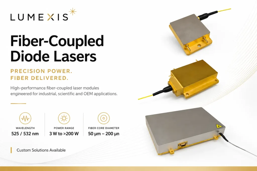
Fiber-coupled pumping involves coupling the outputs of multiple laser diodes into a single optical fiber via a fiber combiner to achieve high-brightness pumping. This approach is suitable for high-power fiber lasers and amplifiers, enabling laser output at the kilowatt level or higher.
The advantages of fiber-coupled pumping include high flexibility and simplified thermal management; the pump source can be separated from the gain fiber, thereby reducing the laser’s footprint while enhancing system stability and reliability. Furthermore, techniques such as wavelength locking and spectral beam combining can be employed to further increase pump brightness and achieve even higher output power.
Brillo, étendue, y por qué el acoplamiento de fibra es la parte difícil
A diode emitter is a poor optical object. Its output is violently divergent in the fast axis and nearly diffraction-limited there, then much less divergent but spatially broad in the slow axis. You cannot fix that by focusing harder. The product of spot size and divergence angle — étendue, or its inverse, brightness — is conserved through any passive optical system. You can trade beam size against angle. You cannot reduce the product.
Every element inside a fibre-coupled module exists to work within that constraint. Fast-axis collimation with a short-focal-length cylindrical microlens tames the divergent axis first, because uncollimated fast-axis light is exactly what overfills a fibre’s numerical aperture. Slow-axis collimation and beam shaping — step mirrors, rotating prism arrays — then redistribute the beam so both axes present comparable étendue. Only after that does focusing into a 105, 135 or 200 µm core at 0.22 NA become possible without discarding half the power at the fibre face.
Once one emitter is in a fibre, brightness scaling continues by combining beams in dimensions that cost no étendue: polarisation combining, which merges two orthogonal states through one aperture; spectral combining, which merges several wavelengths through a dichroic or a grating; and, in fibre, an (N+1)×1 tapered fibre bundle that merges several multimode pump fibres around a signal core.
Volume Bragg grating wavelength locking belongs on this list too. Narrowing a diode from a 3–4 nm free-running spectrum to well under 1 nm and pinning it against temperature is not only a drift fix — it is what makes spectral combining possible at all, and it is what lets you use a narrow absorption feature such as the 976 nm ytterbium peak that a free-running diode would simply walk off.
This is where a supplier’s process either shows up or does not. Automated active alignment during fibre coupling, and verification of delivered power at the connector rather than at the chip, is the whole difference between a datasheet number and a system number. Our manufacturing and test flow is built around that distinction.
Bombeo por extremo versus bombeo lateral
Where you inject the pump light changes what the laser is good at.
End pumping sends the pump in along the resonator axis, usually through a dichroic mirror. Because the pump volume can be shaped to overlap the resonator mode closely, conversion efficiency is high and the output beam quality is excellent. The cost is that the pump beam itself must be good — you are focusing it into a small volume, so brightness matters, and thermal load concentrates in a short length of crystal. Thermal lensing shows up early.
Side pumping fires diode bars radially into the rod. Pump beam quality barely matters, so you can use cheap, high-power bars and scale to multiwatt and higher output. The trade is a less uniform overlap with the resonator mode, which costs efficiency and beam quality.
Cladding pumping is the fiber-laser equivalent and deserves separate mention. Pump light is launched into a large multimode inner cladding rather than the small doped core. It propagates along the fiber, crossing the core repeatedly and being absorbed gradually over meters. This is what makes high-power fiber lasers practical: it decouples pump brightness from the requirement to hit a tiny core, letting relatively modest fiber-coupled diodes drive a single-mode output. It is the architecture behind most 976 nm-pumped ytterbium and erbium-ytterbium systems, including the 1.5 µm sources used in eye-safe LiDAR.
Good side-pumped heads work considerably harder than that description suggests. A common arrangement surrounds the rod with three diode modules at 120° and encloses it in a glass tube whose outer surface is coated high-reflecting at the pump wavelength everywhere except three narrow anti-reflection stripes where the modules inject. The result is a closed pump cavity: light that misses the crystal on its first pass is reflected back and forth until it is absorbed, and because it then arrives from three directions after multiple bounces, the gain distribution across the rod cross-section comes out far more uniform than three discrete beams would imply. Uniform gain is what keeps the thermal lens symmetric, which is what keeps the output beam round.
Defecto cuántico: el calor que no puedes eliminar con el diseño
Pump a laser at 808 nm and extract at 1064 nm, and the energy difference between those photons does not vanish. It becomes heat in the crystal. That fraction is the quantum defect, and it sets a hard floor on thermal load no matter how good your optics are.
At 808 nm into 1064 nm, roughly a quarter of every pumped photon’s energy is lost this way. It is the dominant heat source in a well-built DPSS laser, and heat is what drives thermal lensing, stress birefringence, and eventually crystal fracture.
This is why longer pump wavelengths became interesting. Pumping Nd:YAG at 885 or 888 nm instead of 808 nm cuts the quantum defect by more than half, with a corresponding drop in heat generation. There is a catch, and it is instructive: neodymium’s absorption is much weaker at 880 nm than at 808 nm. Weaker absorption means the pump penetrates further, so you need a longer crystal — 30 mm rather than the 8 mm or less typical of 808 nm designs. In exchange you spread the heat over a longer volume, which is exactly what you wanted.
At 888 nm there is a further benefit worth knowing about. Absorption becomes nearly polarization-insensitive, which removes the need for tight wavelength locking and aggressive temperature control on the pump diodes. For a field-deployed system, dropping a TEC and its control loop is a meaningful reduction in power draw, volume, and failure modes.
That is the shape of most real pumping decisions. There is rarely a free improvement — there is a trade you either make deliberately or discover during qualification.
This family of approaches has a name worth using, because it is what the literature and most datasheets call it: in-band o resonant pumping — depositing pump energy directly into the upper laser level rather than into a higher band that then relaxes into it. Pumping ytterbium at 976 nm to emit at 1030 nm leaves a quantum defect near 5%, roughly a fifth of what 808 nm into 1064 nm costs.
Thulium at 793 nm is the case that breaks the arithmetic in a useful direction. The raw photon-energy difference to 2 µm output looks catastrophic, close to 60%. But thulium exhibits cross-relaxation: one absorbed pump photon can end up exciting two ions, approaching 200% quantum efficiency, which brings the effective thermal load down to roughly 18%. Quantum defect computed from wavelengths alone is a first-order estimate. Before you accept it, check whether your gain medium has an energy-transfer mechanism that changes the answer — 793 nm pump sources exist precisely because it does here.
Referencia rápida de longitud de onda de bombeo
Most of the pumping decision collapses into one table: which wavelengths carry commercial solid-state and fibre lasers, what each is for, and roughly what each costs you in heat.
| Longitud de onda de bomba | Medio de ganancia | Typical output | Approx. quantum defect | Por qué lo elegiría |
|---|---|---|---|---|
| 790 / 792 / 793 Longitud de onda central | Tm, Tm:Ho | 1.9–2.1 µm | ~59% raw, ~18% effective | Cross-relaxation nearly doubles quantum efficiency; 2 µm medical and sensing sources |
| 808 nm | Nd:YAG, Nd:YVO4 | 1064 nm | 24.1% | Strongest Nd absorption, shortest crystal, deepest and cheapest supply chain |
| 878.6 nm | Nd:YVO4 | 1064 nm | 17.4% | In-band pumping; requires a wavelength-locked diode |
| 885 nm | Nd:YAG | 1064 nm | 16.8% | In-band; markedly less heat, at the cost of a longer crystal |
| 888 nm | Nd:YVO4 | 1064 nm | 16.5% | Absorption is nearly polarisation-independent — the most tolerant in-band option, and TEC-friendly |
| 915 nm | Yb-doped fibre | 1070 nm | 14.5% | Broad, flat absorption; drift-tolerant and needs no wavelength locking |
| 976 nm | Yb and Er:Yb fibre | 1030–1070 nm; 1535–1550 nm | 5.2% (1030), 8.8% (1070), 36.4% (1535) | Strongest absorption per unit length, shortest fibre — but the peak is narrow and needs stabilisation |
| 525 nm | Ti:sapphire, alexandrite, dyes and fluorophores | Tunable / visible | Application-dependent | Direct green pumping and fluorescence excitation |
The pattern is consistent, and it is the single most useful thing to carry out of this table: the wavelengths that generate the least heat are the ones with the weakest, narrowest absorption, so they demand a longer crystal or tighter wavelength control in exchange. We build fibre-coupled pump sources across all of these bands, and the trade between thermal load and pump-source discipline is worth settling at the concept stage rather than during qualification.
Vida útil de fluorescencia, almacenamiento de energía y ciclo de trabajo de la bomba
An excited ion does not wait indefinitely. The upper-level fluorescence lifetime is the average time it stays excited before decaying spontaneously, and it settles two commercially important questions: how much energy a Q-switched laser can store, and how long your pump pulse should be.
| Medio de ganancia | Upper-level lifetime | What that means in practice |
|---|---|---|
| Nd:YVO4 | 90–100 µs | High gain, poor storage — suits CW and high-repetition-rate operation |
| Nd:YAG | ~230 µs | The general-purpose compromise; standard for Q-switched marking and ranging |
| Nd:YLF | ~480 µs | Long storage, high pulse energy at lower repetition rate |
| Yb-doped fibre | ~800 µs – 1 ms | Very high storage; also why Yb amplifiers tolerate gentle pumping |
| Er:vidrio | Milliseconds | Exceptional storage — the basis of compact eye-safe 1535 nm transmitters |
Nd:YVO4 and Nd:YAG make the trade concrete. Vanadate’s emission cross-section is roughly five times that of YAG, which is why it lases at lower threshold and higher gain. But cross-section and lifetime pull in opposite directions: the same property that gives vanadate its gain drains the upper level in under 100 µs. YAG holds population longer and therefore yields more energy per Q-switched pulse.
The rule that follows is blunt: pumping for much longer than the upper-level lifetime does not store more energy. It just heats the crystal. Which is why pump duty cycle is a specification and not a detail:
- CW pumping — constant current, steady thermal load, stable thermal lens. Correct for continuous output and for repetition rates high enough that the thermal state never really changes.
- QCW pumping — the pump runs for a few hundred microseconds around each output pulse, then switches off. Because the diode dissipates during only a small fraction of the cycle, it can be driven to peak currents several times its CW rating, delivering far higher peak pump power from the same package while average thermal load stays low. The pump pulse should be on the order of the upper-level lifetime; longer buys nothing.
- Pulsed and burst modes — everything else, usually dictated by an application duty cycle rather than by the gain medium.
For a battery-powered rangefinder firing a few pulses per second, QCW is not an optimisation — it is the reason the product can exist at all. Er:vidrio holds its inversion for milliseconds, so a modest diode can pump it slowly and a Q-switch can dump the result as a single high-peak-power 1535 nm pulse: eye-safe, and bright enough for kilometre-class telemetría from a handheld or UAV-mounted head. The same logic scales up in erbium-doped fibre for 1.5 µm LiDAR sources.
A datasheet that quotes only CW power tells you nothing about QCW capability. Ask for peak current rating, maximum pulse width and duty-cycle limit together — those three numbers, not the CW figure, decide what pulse energy you can build.
Lo que realmente se rompe: deriva de longitud de onda y gestión térmica
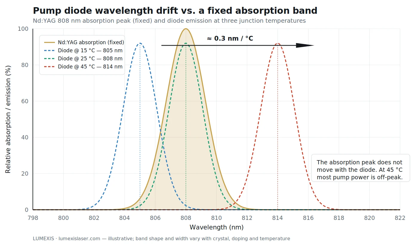
A pump diode’s emission wavelength moves with junction temperature, typically around 0.3 nm per °C. The gain medium’s absorption peak does not move with it.
Run the math on that and the problem is obvious. A diode specified at 808 nm at 25 °C is emitting closer to 811 nm at 35 °C. If your crystal’s absorption band is a few nanometers wide, you have walked partly off the peak, absorbed less pump, and lost output — and the shortfall gets blamed on the crystal or the resonator, because those are easier to inspect.
Three approaches exist, and they suit different products.
Active temperature control with a TEC holds the diode at a fixed junction temperature. It works, and it costs power, volume, and a control loop that can itself fail. On a battery-powered or size-constrained platform this is often the wrong answer.
Wavelength-stabilized diodes using a volume Bragg grating lock emission largely independent of temperature. This costs more per diode and typically some efficiency, but it removes the TEC.
TEC-less design accepts the drift and engineers around it — choosing a broader absorption feature, biasing the nominal wavelength so the drift lands on-peak at the most demanding operating point, or accepting a specified output derating across temperature. Done deliberately, this produces the simplest and most robust system. Done accidentally, it produces a laser that works in the lab and disappoints in the field.
Our team designs for TEC-less operation wherever the application allows it, because for UAV, vehicle-mounted, and handheld platforms the removed complexity is usually worth more than the last few percent of efficiency. That analysis is application-specific, though, and it belongs in the first design review rather than the qualification phase.
Temperature control is only the last link in the chain. The junction temperature that sets your wavelength is the sum of everything between the active region and your cold plate: submount, solder, baseplate, thermal interface material. Aluminium nitride and copper-tungsten submounts are used because they conduct well and, more importantly, because their thermal expansion is close to the semiconductor’s — a mismatch here does not cause a thermal problem, it causes a mechanical one, as every power cycle works the solder joint a little further. Diamond appears where power density leaves no alternative.
Above that stack the choice is conduction cooling to a chassis, which is simple and sealed, or microchannel water cooling, which handles far higher flux but adds plumbing, corrosion and a failure mode that takes the diode with it.
Get this wrong and the failure is not gradual. Catastrophic optical mirror damage is the emitting facet melting under its own optical field, and it is a single-event, unrecoverable failure. Slow facet oxidation in a non-hermetic package is the same story told over years. Both are why derating matters: a diode run at 70% of rated current typically lives several times longer than one run at 100%, and that is usually a cheaper way to buy lifetime than a larger cooler.
La cadena de eficiencia: a dónde van realmente 100 vatios eléctricos
Quantum defect is the loss engineers quote, but it is one term in a chain, and the chain is multiplicative. Work an 808 nm-pumped Nd:YAG example end to end with ordinary — not optimistic — numbers:
| Stage | Typical factor | Running total from 100 W electrical |
|---|---|---|
| Diode electrical-to-optical conversion | 55% | 55 W optical |
| Coupling into the delivery fibre | 90% | 49.5 W at the fibre end |
| Delivery and mode matching into the crystal | 92% | 45.5 W incident |
| Absorption in the crystal | 92% | 41.9 W absorbed |
| Quantum defect, 808 → 1064 nm | 75.9% retained | 31.8 W as 1064 nm photons |
| Upper-state losses, resonator losses, output coupling | ~60% | ≈19 W out |
Roughly 19% wall-plug, and about 81 W of heat spread across the diode package, the coupling optics and the crystal. Two things fall out of that table. First, the largest single loss is the diode itself, not the quantum defect — which is why diode efficiency and coupling efficiency deserve the scrutiny normally reserved for the resonator. Second, moving to 888 nm improves exactly one line of this table, from 75.9% to 83.5% retained — worth around 2 W of extra output, but a great deal more in reduced crystal heating and thermal lensing.
Run the table with your own numbers before you commit to an architecture. It is the fastest way to find out whether your thermal budget is realistic, and it usually reorders the priority list.
Cómo leer una hoja de datos de diodo de bomba con escepticismo
Pump modules are commodity-priced and are not commodities. The differences that matter are mostly not on the front page of the datasheet.
Is the wavelength a specification or a typical value, and at what case temperature? A center wavelength quoted without a reference temperature and a tolerance is not a number you can design to.
What is the coupling efficiency into the delivery fiber, and how was it measured? Fiber-coupled power at the connector is the number that matters to your system. Chip power is not.
¿Se examinó cada unidad con quemado, o solo una muestra? Diode lasers show early-life failures. Burn-in is the only practical way to find them before they find your customer, and screening every unit costs the supplier real yield — which is why some skip it.
What does the package do about moisture? Hermetic sealing is what keeps facet degradation from accumulating over years in humid or cycled environments. An unhermetic package can look identical on a datasheet and behave very differently at year three.
Is there data across the full operating window? Performance at 25 °C tells you almost nothing about performance at −40 °C or +70 °C. Ask for the temperature-cycled data, not the ambient bench test.
This is the reasoning behind how we build fuentes de bomba de diodo acopladas por fibra: incoming inspection, chip test, die bonding and chip-on-submount assembly, automated fiber coupling, hermetic sealing by parallel seam welding, then burn-in and full-window temperature cycling before final test. The vertical integration matters less as a marketing point than as a traceability one — when a unit behaves oddly, we can find out why. You can see the manufacturing and test capability behind that flow, or browse módulos de fuente láser disponibles si está evaluando una longitud de onda y potencia específicas.
Preguntas frecuentes
¿Cuál es la diferencia entre bombeo y emisión láser?
El bombeo introduce energía en el medio de ganancia para crear inversión de población. El láser es lo que ocurre después: la emisión estimulada amplifica la luz dentro de un resonador hasta que se convierte en un haz de salida coherente. El bombeo es la entrada; el láser es el resultado.
¿Por qué se utilizan diodos láser para bombear otros láseres?
La emisión del diodo puede ajustarse a una banda de absorción estrecha del medio de ganancia, por lo que casi toda la energía de bombeo se absorbe de manera útil en lugar de convertirse en calor. Las lámparas de destello emiten luz de banda ancha, la mayor parte de la cual se desperdicia. Los diodos también duran mucho más y funcionan a un voltaje mucho más bajo.
¿Qué es el defecto cuántico en el bombeo láser?
Es la diferencia de energía entre un fotón de bombeo y un fotón láser, liberada como calor en el medio de ganancia. Bombear Nd:YAG a 808 nm para emitir a 1064 nm pierde aproximadamente una cuarta parte de la energía del fotón de bombeo de esta manera. Esto establece la carga térmica mínima del diseño.
¿Qué significa end pumping?
La luz de bombeo entra a lo largo del eje del resonador, generalmente a través de un espejo dicroico, por lo que el volumen bombeado se superpone estrechamente con el modo láser. Esto proporciona alta eficiencia y buena calidad de haz, pero concentra el calor y requiere una fuente de bombeo razonablemente brillante.
¿Necesitan las bombas de diodos control de temperatura?
No siempre. La longitud de onda de emisión se desplaza aproximadamente 0,3 nm por °C, por lo que algunos diseños usan un TEC o un diodo estabilizado en longitud de onda. Otros están diseñados para funcionar sin TEC eligiendo una banda de absorción tolerante y ajustando la longitud de onda nominal — más simple y robusto cuando la aplicación lo permite.
¿Por qué se utiliza 976 nm para el bombeo de láseres de fibra?
Las fibras dopadas con iterbio y erbio-iterbio tienen una fuerte característica de absorción cerca de 976 nm. Combinado con el bombeo por revestimiento, esto permite que los diodos acoplados a fibra multimodo impulsen eficientemente una salida de modo único — la base de la mayoría de los sistemas de láser de fibra de alta potencia y de 1.5 µm seguros para el ojo.
¿Cuáles son los principales tipos de bombeo láser?
Bombeo óptico (lámparas de destello o, mucho más comúnmente ahora, diodos láser), bombeo eléctrico (una descarga de gas, o corriente a través de una unión semiconductora) y bombeo químico (energía de una reacción). El bombeo óptico por diodo se subdivide además en geometrías de extremo, lateral, acoplada a fibra y bombeada por revestimiento, y esa elección de geometría suele importar más a un producto que la categoría en sí.
¿Cuál es la diferencia entre el bombeo CW y QCW?
El bombeo CW hace funcionar el diodo de forma continua con una carga térmica estable. El bombeo QCW lo hace funcionar en pulsos cortos, típicamente de unos cientos de microsegundos, alrededor de cada pulso de salida. Debido a que el diodo solo disipa durante una fracción del ciclo, se puede accionar muy por encima de su corriente nominal CW, lo que proporciona una potencia de bombeo máxima mucho mayor desde el mismo encapsulado. El QCW es lo que hace prácticos los láseres pulsados compactos alimentados por batería, como los telémetros.
¿Qué es el bombeo en banda o resonante?
Pumping directly into the upper laser level instead of into a higher absorption band that must then relax into it. It cuts the quantum defect sharply — 888 nm into Nd:YVO4 instead of 808 nm, or 976 nm into ytterbium for 1030 nm output. The cost is weaker absorption, so the crystal or fibre has to be longer.
¿Cuánto debería durar un pulso de bombeo?
On the order of the gain medium’s upper-level fluorescence lifetime — roughly 230 µs for Nd:YAG, under 100 µs for Nd:YVO4, milliseconds for Er:glass. Pumping much longer than that does not store additional energy; it only adds heat.
Especificar la bomba antes de especificar el láser
If you are early in a design, settle the pump questions first: wavelength and its tolerance across your real operating temperature, delivered power at the fiber, geometry, and whether you can live without a TEC. Those four answers constrain the resonator far more than the resonator constrains them.
Send us your gain medium, output requirement, and environmental envelope, and nuestros ingenieros trabajarán con usted en las opciones de bomba — including the trade between wavelength stabilization and TEC-less simplicity for your specific platform.
Referencias
- RP Photonics Encyclopedia — Optical Pumping
- Coherent — What is Laser Pumping?
- Laser Focus World — Enhance your Nd-doped DPSS laser with a longer-wavelength pump
- Gentec-EO — What is population inversion in a laser?
- RP Photonics Encyclopedia — Quantum Defect
- RP Photonics Encyclopedia — Upper-state Lifetime
- RP Photonics Encyclopedia — Brightness
- RP Photonics Encyclopedia — Double-clad Fibers
- RP Photonics Encyclopedia — Wavelength-stabilized Laser Diodes