
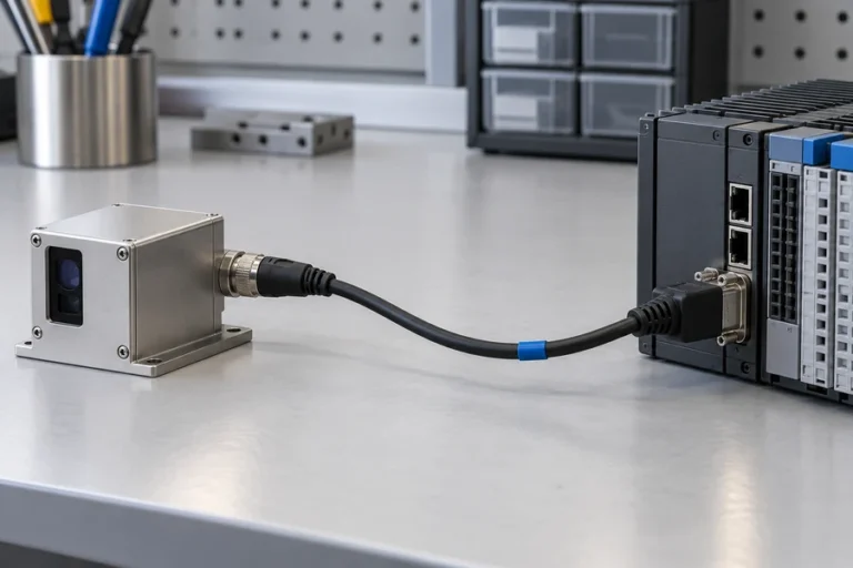



A CAN connector can make a laser rangefinder look ready for a shared machine network. Yet the connector does not define the bit rate, frame identifiers, payload units, update policy, termination, startup state, or recovery behavior. Those missing decisions are where many integrations lose time.
A CAN bus laser rangefinder combines a ranging module with a CAN controller and transceiver so it can exchange frames on a differential multi-node bus. Reliable integration requires the same physical-layer configuration at every node, a documented application protocol, planned message priority and timing, correct backbone termination, and host logic that rejects stale or invalid range data.
CAN bus laser rangefinder integration starts with the protocol boundary
CAN provides the data-link behavior used to move frames and arbitrate access to a shared bus. It does not tell an OEM what a distance payload means. The module supplier still needs to define the application contract: which identifier carries a range result, how the payload is encoded, what units apply, how invalid measurements are reported, and which commands change configuration.
Do not assume that CAN, CANopen, and other higher-layer protocols are interchangeable. A module may use raw Classical CAN frames, CAN FD, CANopen, or a supplier-specific protocol. Products using the same transceiver may still have incompatible bit timing, identifiers, payloads, or network management.
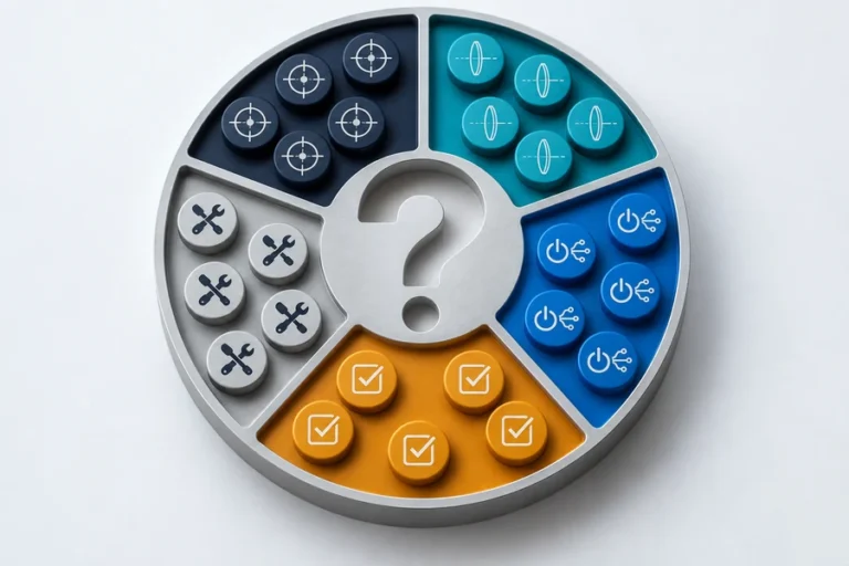
Freeze these items before the host design is released:
- physical interface, frame format, and bit timing;
- identifier and priority plan;
- command, status, range-data, and diagnostic payloads;
- update, timeout, startup, configuration, and recovery rules.
Unsere laser rangefinder module interface comparison helps teams decide when a shared CAN network is a better fit than UART, RS-232, or RS-422. That architecture choice should be made from the installed harness, node count, timing needs, and service workflow.
Plan message priority from the system deadline
CAN uses bitwise arbitration when more than one node starts transmitting. A node monitors the bus while it sends its identifier. If it transmits a recessive bit but reads a dominant bit, it stops competing and becomes a receiver; the higher-priority frame continues without being destroyed. In Classical CAN, the numerically lower arbitration field wins.
That mechanism is useful, but it does not make every message timely. A range update can still be delayed by higher-priority traffic, long frames, repeated retries, or an overloaded schedule. The identifier plan therefore needs to reflect system deadlines rather than department ownership or an arbitrary numbering sequence.
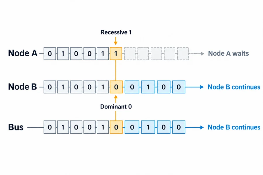
For each range message, define the maximum acceptable age at the consumer. Budget acquisition, processing, queueing, arbitration, transmission, parsing, and application response. Measure worst-case latency on the complete network, not only on a quiet one-node bench.
Avoid assigning every important message the highest priority. That simply moves the delay to another function and can starve lower-priority traffic. Build a reviewed identifier map with owners, periods, deadlines, payload lengths, and expected bus load. Reserve diagnostic traffic so it cannot unexpectedly dominate measurement data during a fault.
Define the range-data contract beyond the eight payload bytes
A receiver needs to know whether a distance is fresh, valid, in range, and associated with the expected mode. A practical contract includes the value, scale, status, freshness indicator, and any documented target state the module supports.
Do not invent a quality field when the released module does not provide one. Instead, define host-side rules around documented states and timing. A timeout, startup frame, out-of-range result, internal fault, or configuration response must not be passed downstream as an ordinary distance.
Record these protocol items in a version-controlled interface document:
- identifier, frame format, and data length;
- byte order, signedness, scale, offset, and units;
- request, periodic, event-driven, or mixed transmission;
- acknowledgments, negative responses, and fault representations;
- timeout, restart, duplicate-frame, and compatibility behavior.
This contract belongs beside the optical, mechanical, power, and thermal controls in the laser rangefinder module integration process. A valid bus frame is not proof that the optical measurement is valid, and a valid measurement is not enough if the host cannot determine when it was produced.
Use a terminated backbone and control every stub
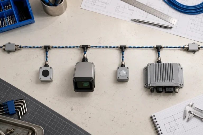
High-speed CAN is normally wired as a linear backbone with termination at the two physical ends. Microchip and NI describe the common arrangement as a nominal 120-ohm termination at each end of a 120-ohm differential bus. The two resistors appear as roughly 60 ohms across CAN_H and CAN_L when the network is unpowered, provided no other loading changes the reading.
The word “end” refers to the physical cable, not the first and last node in software. Intermediate nodes connect through stubs, which add propagation delay and reflection risk. Keep them short for the selected bit rate and transceiver guidance; do not turn the backbone into a star for harness convenience.
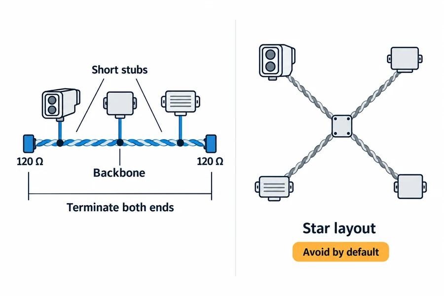
Treat built-in termination as a configuration item. If a module includes a switchable resistor, document whether it is enabled for each installation position. A sample on a two-node bench may work with internal termination enabled, then overload the production network when it is installed as a middle node.
Select cable, connectors, grounding, protection, and common-mode strategy as a system. Follow the chosen transceiver datasheet and host electrical requirements rather than copying a generic circuit.
Match bit timing and network management at every node
All nodes must share compatible bit timing. A nominal rate alone is incomplete; controller configuration also depends on the clock, time quanta, propagation and phase segments, synchronization jump width, and sample point. Use the component vendor’s method and validate the actual controller and transceiver population.
If the module uses CANopen or another higher layer, match node identifiers, message configuration, startup, supervision, and state transitions. A SICK CANopen distance-sensor manual separates network bit rate from process-data mapping and event timing, illustrating why physical communication and application meaning need separate controls.
For a supplier-specific protocol, request the same level of clarity. The deliverable should include an identifier table, byte-level definitions, state behavior, configuration persistence, error responses, and at least one known-good exchange. Source code is helpful, but it should not be the only specification.
Design stale-data and fault behavior before normal operation
The host must know what happens when the rangefinder stops publishing, repeats an old frame, restarts, reports a fault, or leaves the bus. Define a data-age timer at the consumer. When it expires, mark the measurement unavailable and propagate that state explicitly. Do not hold the last range indefinitely as though it were current.
Separate three fault domains: an unusable optical result, a frame or payload violation, and a network communication fault. Each needs a different diagnostic record and recovery owner.
CAN controllers include error detection and confinement behavior, but system recovery remains an application decision. Specify whether the module recovers automatically, needs a host command, or requires a power cycle after a bus-off condition. Define how the host distinguishes recovery from a fresh measurement and how quickly the wider machine can trust the node again.
Validate on the final network, not a USB adapter alone
Begin with a controlled two-node setup to confirm polarity, termination, bit timing, identifiers, and payload decoding. Then move to a production-representative backbone with the final cable, node count, power, and grounding. Add realistic traffic and fault injection only within a documented test plan.
Use electrical and protocol evidence. Check unpowered resistance, inspect differential signals with suitable probing, record error counters, and capture frames. Verify data age, units, invalid states, acknowledgments, restart, timeout, and configuration persistence.
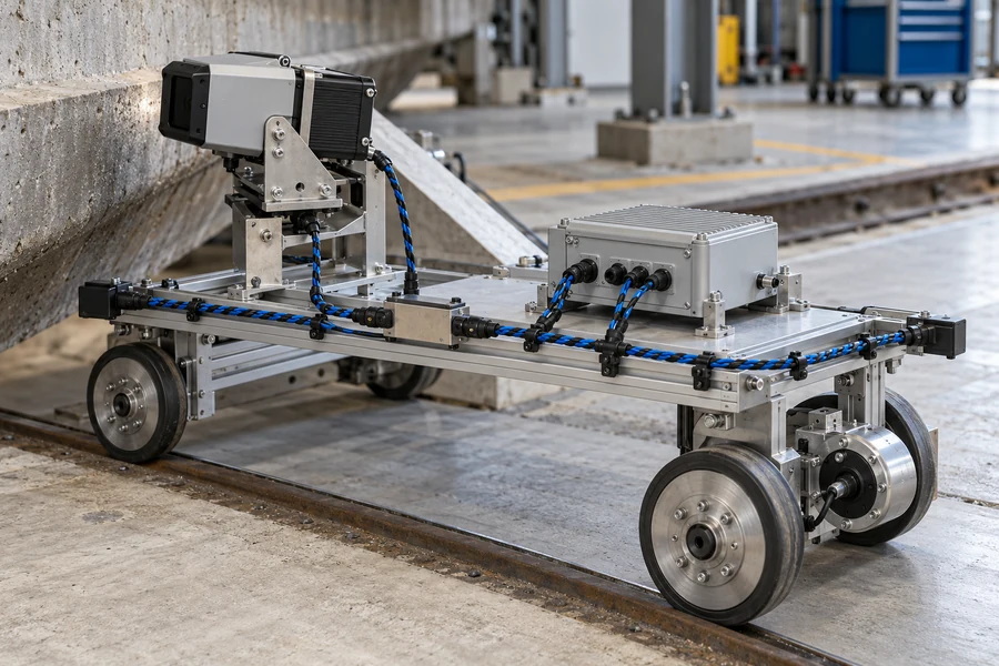
Finally, repeat the critical cases over the required temperature and power conditions using the released firmware and harness. The rangefinder test guide explains how to turn test conditions and acceptance rules into comparable evidence instead of a collection of successful demonstrations.
When a CAN interface is the right choice
CAN is useful when a laser rangefinder must share a robust differential network with several controllers or sensing nodes, and when deterministic message priority, diagnostics, and managed recovery matter. It is less attractive for a single short internal link with minimal software overhead or when the host has no CAN controller and the wider system gains no value from adding one.
Lumexis applications engineers support module selection, interface definition, integration, validation, and troubleshooting. Our Wuxi office works with the 14,000-square-meter Taizhou manufacturing base, where electronics, firmware, optomechanical design, cleanroom assembly, burn-in, and final testing support repeatable OEM supply.
Der Lumexis laser rangefinder module family provides a starting point for range, wavelength, envelope, power, and interface discussions. Standard products can ship within three days when confirmed available. Custom configurations and private-label projects need a separately reviewed scope and lead time through our Engineering-Service.
FAQ
Does CAN define the laser rangefinder data format?
No. CAN defines frame transport, arbitration, error handling, and related link behavior. The module’s application protocol defines identifiers, payload bytes, units, status values, commands, and timing. Request the released protocol document for the exact module and firmware revision.
Is CANopen the same as CAN?
CANopen is a higher-layer protocol built on CAN. A raw-CAN rangefinder and a CANopen rangefinder can use similar transceivers while remaining incompatible at the application layer. Confirm the higher-layer protocol, profile, object mapping, node configuration, and network-management behavior.
Where should the CAN termination resistors go?
For a typical high-speed linear CAN network, termination belongs at the two physical ends of the backbone. Middle nodes should not add full termination unless the approved topology specifically requires it. Verify the network unpowered and document any switchable internal termination.
Can several rangefinders share one CAN network?
Yes, if every node has compatible bit timing and a non-conflicting identifier or node plan, while the combined traffic meets latency and bus-load requirements. The host must also distinguish each measurement source and handle missing or stale data per node.
What should happen when range data stops arriving?
The consumer should expire the measurement after a defined maximum age, mark it unavailable, and follow the system’s controlled recovery policy. It should not reuse the last valid distance as a new reading. Log the bus state, protocol state, and module status separately.
Referenzen
- CAN in Automation, CiA glossary of CAN terms.
- Microchip Technology, A CAN Physical Layer Discussion, AN228.
- NXP Semiconductors, Application Hints for High-Speed CAN Transceivers, Rev. 01.50.
- SICK, DL100 Pro CANopen Operating Instructions, 2023.
Send our Engineering-Team the target and range envelope, CAN format, bit timing, identifier map, payload contract, node count, harness topology, power budget, operating environment, and validation plan. We can recommend a standard module, confirm three-day shipment for an available standard configuration, or review a custom/private-label requirement with an applications engineer.